Hydroboost Plumbing Diagram: Step-by-Step Instructions
A hydroboost plumbing diagram provides a comprehensive layout for high-efficiency sink systems. It illustrates the sequence from the tailpiece through the garbage disposal and into the P-trap. By following this guide, you ensure the drain assembly and vent pipe work together to maintain pressure and prevent sewer gas leaks.
📌 Key Takeaways
- Illustrate the correct sequence for high-flow sink drainage
- The P-trap is vital for stopping sewer gases and maintaining the water seal
- Always ensure the vent pipe is unobstructed to prevent siphoning
- Use plumber’s putty on the drain assembly to prevent hidden leaks
- Refer to this diagram when installing high-capacity disposal units
Navigating the complexities of modern sink drainage requires a clear visual reference and a solid understanding of fluid dynamics. Whether you are installing a high-efficiency kitchen sink or retrofitting a utility area, having a comprehensive hydroboost plumbing diagram is essential for ensuring that your system operates without leaks, odors, or slow drainage. This guide is designed to provide you with a deep dive into the architecture of a high-performance drainage system, focusing on the critical components that maintain the “hydroboost” effect—optimized air pressure and smooth water flow. You will learn how to identify every part of the drain assembly, how to properly vent your system using an AAV valve, and the step-by-step process for a professional-grade installation that meets modern building codes.
A “hydroboost” plumbing configuration typically refers to a drainage system optimized for high-volume discharge, often incorporating an Air Admittance Valve (AAV) to ensure that the vacuum created by fast-moving water does not siphon the P-trap dry.
Decoding the Hydroboost Plumbing Diagram
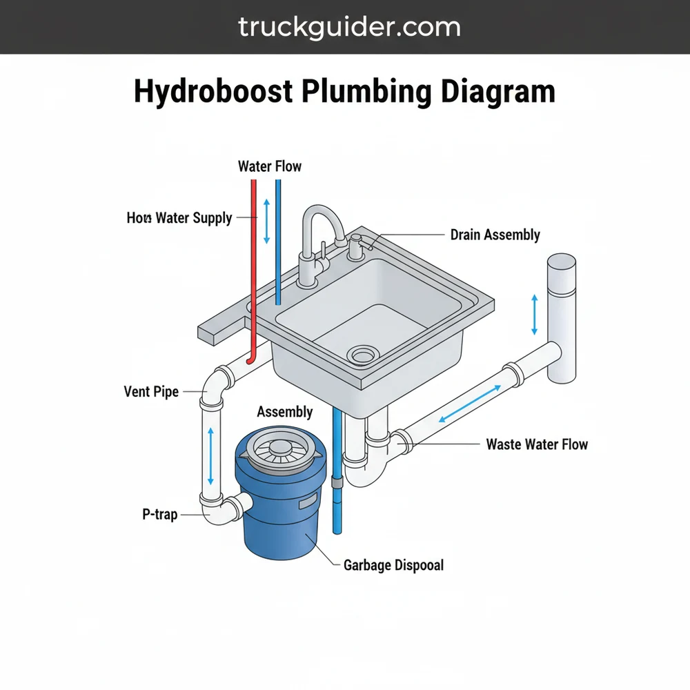
Understanding a hydroboost plumbing diagram requires looking at the sink’s underside not just as a collection of pipes, but as a balanced pressure system. The diagram illustrates the path of wastewater from the moment it enters the sink strainer until it exits through the main waste line in your wall or floor. The primary goal of this layout is to move water out as quickly as possible while preventing sewer gases from entering your living space.
At the top of the diagram, you will find the drain assembly. This is the hardware that physically connects to the sink basin. In a kitchen setting, this often includes a garbage disposal unit. The discharge from the disposal or the sink strainer leads into the tailpiece. The tailpiece is a straight section of pipe that bridges the gap between the sink and the trap. In a hydroboost setup, the tailpiece must be perfectly vertical to ensure gravitational velocity is maintained.
The central feature of any plumbing diagram is the P-trap. This U-shaped pipe is designed to hold a small amount of water at all times, creating a liquid seal. The diagram will show the “trap arm” extending from the P-trap to the wall. A critical element often featured in modern “boosted” systems is the AAV valve (Air Admittance Valve). In the diagram, this is positioned above the highest drainage point on a vertical branch. It allows air to enter the system when negative pressure occurs (as water rushes down the pipe), preventing the “glugging” sound of a struggling drain and protecting the P-trap seal.
[DIAGRAM_PLACEHOLDER: A detailed technical illustration showing a dual-basin sink. On the left, a garbage disposal connects to a baffle tee. On the right, a standard drain assembly leads to a tailpiece. Both converge into a central P-trap. Behind the P-trap, a vertical PVC pipe rises to an AAV valve, while the horizontal waste arm connects to a 1.5-inch PVC wall drain via slip joints.]
The materials indicated in the diagram are typically PVC (Polyvinyl Chloride) or ABS (Acrylonitrile Butadiene Styrene) plastic. PVC is favored for its durability and ease of use with slip joint connectors. Slip joints are the adjustable nuts and washers that allow you to hand-tighten connections, making the system easy to service or adjust during installation. The diagram will also distinguish between “solvent weld” connections (which are glued) and “mechanical” connections (which use nuts and washers).
Installation Guide: Step-by-Step Implementation
📤 Share
💾 Download
To successfully translate a hydroboost plumbing diagram into a working system, follow these structured steps. This process ensures that every component is aligned for maximum flow efficiency and a long-lasting, leak-free seal.
Step 1: Preparation and Tool Gathering
Before beginning, clear out the area under the sink and ensure you have the necessary tools. You will typically need a hacksaw or PVC cutter, a pair of channel-lock pliers, a bucket for catching residual water, and plumber’s putty or silicone sealant. Check your diagram to confirm the size of your pipes; most residential kitchen drains use 1.5-inch PVC, while some older systems or bathroom sinks use 1.25-inch pipes.
Step 2: Installing the Drain Assembly
Apply a bead of plumber’s putty around the underside of the sink strainer flange. Drop it into the sink hole and press firmly. From underneath, slide on the rubber gasket and the friction washer, then tighten the large mounting nut. If you are installing a garbage disposal, follow the manufacturer’s instructions to attach the mounting ring. The disposal acts as the primary “pump” in your hydroboost system, so ensuring a vibration-free mount is vital.
Do not over-tighten the mounting nuts on plastic sinks or thin stainless steel basins. Excessive force can crack the basin or deform the flange, leading to permanent leaks.
Step 3: Attaching the Tailpiece and Baffle Tee
If you have a double sink, you will use a baffle tee to join the two sides. The tailpiece drops down from the strainer. Slide a slip joint nut and a plastic washer onto the tailpiece. The washer’s beveled side should always point toward the joint. Insert the tailpiece into the tee or the P-trap intake. Adjust the height as indicated in your hydroboost plumbing diagram to ensure there is a slight downward slope once the pipe turns horizontal.
Step 4: Configuring the P-Trap
The P-trap consists of two parts: the U-bend and the J-bend (trap arm). Connect the U-bend to the bottom of the tailpiece. The P-trap must sit level. Its job is to provide a water seal of at least 2 inches but no more than 4 inches. If the trap is too deep, solids may settle and cause clogs; if it is too shallow, the seal can evaporate or be siphoned away.
Step 5: Integrating the AAV Valve (The Boost)
In many modern configurations, especially in island sinks or where a vent pipe is difficult to reach, an AAV valve is the secret to high-performance drainage. Install a sanitary tee on the horizontal trap arm. The top of the tee should lead to a vertical pipe that extends as high as possible under the cabinet (at least 4 inches above the trap). Screw the AAV valve onto the top of this vertical pipe. This valve allows air to enter the drain when water flows through, significantly “boosting” the drainage speed by preventing air lock.
- ✓ Ensure the AAV is installed in an upright, vertical position.
- ✓ The AAV must be located in a space with adequate air circulation.
- ✓ Check local codes, as some jurisdictions have specific height requirements for AAVs.
Step 6: Connecting to the Wall Waste Line
Measure and cut the trap arm to reach the waste pipe in the wall. Use a transition coupling if you are moving from one material to another (e.g., from old metal pipes to new PVC). Ensure the horizontal run has a “pitch” or slope of 1/4 inch per foot. If the pipe is level or sloped backward, water will stand in the pipe, leading to eventual blockages and corrosion.
Step 7: Final Tightening and Testing
Hand-tighten all slip joints first. Once everything is aligned according to your hydroboost plumbing diagram, give each nut an additional quarter-turn with your pliers. Fill the sink basins to the brim and then release them simultaneously. This “stress test” checks for leaks under high pressure and ensures the venting system (AAV) can handle the maximum flow rate.
Troubleshooting Common Drainage Issues
📤 Share
💾 Download
Even with a perfect diagram, real-world plumbing can present challenges. One of the most common issues is a “slow drain” despite having a clear pipe. This is often caused by poor venting. If the air cannot get in, the water cannot get out. Check your AAV valve; if it is stuck closed, it will create a vacuum that slows the water down. You can test this by temporarily unscrewing the valve; if the sink drains faster, the valve needs replacement.
Another frequent problem is leakage at the slip joints. This usually happens because the plastic washer is misaligned or has been crushed. Always ensure the tapered end of the washer is facing the correct direction—into the joint. If you notice a “sewer smell,” it means your P-trap has lost its seal. This could be due to siphoning (lack of air) or the sink not being used for a long period, allowing the water to evaporate. Your hydroboost plumbing diagram helps you identify exactly where these seals are located so you can troubleshoot the specific failure point.
When troubleshooting a gurgling sound, check the vent pipe roof terminal. Sometimes a bird’s nest or debris can clog the main vent, forcing the system to pull air through your P-trap, which creates that distinct noise.
Best Practices for a High-Performance System
To keep your plumbing running at peak efficiency, follow these professional best practices. First, always prioritize the use of sweeping 90-degree elbows rather than “short” or “tight” elbows. Sweeping turns allow waste to maintain momentum, reducing the likelihood of buildup. When using PVC, always clean the pipe ends and use a high-quality primer before applying solvent cement on permanent joints.
Maintenance is also key. Once a month, flush your drains with a gallon of boiling water to melt away fats and greases that may have adhered to the PVC walls. Avoid using harsh chemical drain cleaners, as the heat generated by the chemical reaction can actually soften or deform thin-walled PVC pipes over time. Instead, use enzymatic cleaners that break down organic matter safely.
Lastly, consider the quality of your components. While plastic slip joint nuts are standard, heavy-duty nylon nuts and thick rubber washers provide a much better seal than the cheap, thin plastic versions found in bulk kits. If your hydroboost plumbing diagram includes a dishwasher connection, ensure the dishwasher drain hose has a “high loop” or is connected to an air gap to prevent dirty sink water from backflowing into your clean dishes.
Conclusion
A properly executed hydroboost plumbing diagram is the blueprint for a quiet, efficient, and sanitary home. By understanding the relationship between the drain assembly, the P-trap, and the venting system, you can tackle sink installations with professional confidence. Remember that the “boost” in your drainage comes from the perfect balance of gravity and air pressure. Whether you are troubleshooting a persistent clog or building a new kitchen from scratch, keeping these principles and components in mind ensures your plumbing remains a worry-free part of your home’s infrastructure. Always refer back to your specific layout, respect the physics of the P-trap, and ensure your AAV valve or vent pipe is clear to maintain the high-performance flow your household requires.
Frequently Asked Questions
Where is the P-trap located?
The P-trap is situated directly beneath the sink basin, connecting the tailpiece to the wall drain. In a hydroboost plumbing diagram, it serves as a water seal to prevent sewer gases from entering your home. It must be accessible for cleaning and properly aligned with the drain assembly for efficiency.
What does a hydroboost plumbing diagram show?
This diagram provides a visual map of the entire drainage system, including the tailpiece, garbage disposal, and P-trap. It shows the specific path water takes through the drain assembly and how the vent pipe regulates pressure to ensure a smooth, high-capacity flow without any siphoning or backup issues.
How many connections does the drain assembly have?
A standard drain assembly in a hydroboost system typically features three main connections: the sink strainer interface, the dishwasher inlet port on the garbage disposal, and the primary outlet leading to the P-trap. Ensuring each connection is sealed with a gasket or plumber’s putty is vital for performance.
What are the symptoms of a bad vent pipe?
Symptoms of a failing or blocked vent pipe include slow drainage, gurgling sounds coming from the P-trap, and recurring sewage odors. If the vent cannot regulate air pressure, the hydroboost plumbing diagram’s effectiveness is compromised, often leading to a complete backup within the garbage disposal or the main drain.
Can I install this plumbing myself?
While a DIY enthusiast can install basic components like a tailpiece or garbage disposal, a full hydroboost plumbing setup can be complex. It requires precise alignment of the vent pipe and drain assembly. If you are uncomfortable with high-pressure fittings or local building codes, hiring a professional plumber is recommended.
What tools do I need for this task?
To complete this task, you will need a pipe wrench, slip-joint pliers, a screwdriver, and plumber’s putty. Additionally, having a hacksaw for trimming the tailpiece and a bucket to catch excess water from the P-trap is essential. These tools ensure a secure, leak-free installation of your entire system.


![2008 Dodge Avenger Battery Location [2026]](https://truckguider.com/wp-content/uploads/2026/03/featured-98241f46-768x768.webp)