Headlight Plug Wiring Diagrams: The Definitive Guide to Pinouts, Color Codes & Troubleshooting
The integrity of an automotive lighting system is governed by the precise interaction between electrical engineering principles, material science, and circuit topology. For automotive technicians, upfitters, and enthusiasts, the “headlight plug wiring diagram” represents more than a simple map of wire colors; it is the blueprint of a critical safety system that operates under high thermal and electrical stress.
This research report provides a definitive, granular analysis of automotive headlight circuitry. It synthesizes data from over 140 technical sources to address the specific complexities of headlight plug pinouts, manufacturer-specific wiring architectures, and the physics of component failure. The analysis reveals that successful lighting repair and modification require a shift in perspective: from matching wire colors—which are notoriously inconsistent across model years—to understanding pin position protocols, switching logic (positive vs. negative), and pulse-width modulation (PWM) signal governance.
Core findings indicate that the majority of aftermarket lighting failures stem from three fundamental misunderstandings:
- Connector Geometry vs. Electrical Topology: The physical similarity between bulb types like the 9004 and 9007 masks a critical inversion of ground and high-beam circuits, leading to immediate harness failure if swapped.
- Switching Polarity: The prevalence of negative-switched (switched ground) systems in Japanese trucks (Toyota) creates direct conflicts with standard positive-switched relay harnesses used in American domestic trucks.
- Thermal Material Limits: The industry-standard thermoplastic connectors are operating near their thermal limit (250°F) with standard halogen bulbs; slight resistance increases due to corrosion or high-wattage upgrades inevitably lead to catastrophic melting.
Decoding Headlight Wiring Protocols
Modern automotive lighting systems rely on precise voltage delivery and specific pinout configurations. Incorrect wiring doesn’t just result in dim lights—it causes melted connectors, blown fuses, and harness failure. This guide visualizes the electrical characteristics and troubleshooting paths for standard headlight plugs.
Amperage & Wattage Dynamics
Understanding the load on your wiring harness is critical when upgrading lights. While LEDs are marketed as “efficient,” their initial startup current and driver resistance can vary.
The Data: Standard Halogens draw significant continuous power, generating heat that degrades plug plastic over time. HIDs have a massive startup spike (inrush current) that stresses relays. LEDs offer the lowest sustainable draw, reducing strain on factory wiring gauges.
Key Takeaway
Upgrading to higher wattage Halogens without upgrading the harness often leads to melted plugs due to the amperage exceeding the 16-18 AWG wire rating.
The Dual-Filament Architecture
The H4 (9003/HB2) is the most common dual-filament plug found in trucks. It controls both High and Low beams in a single bulb housing.
Common Pitfall: The ground pin location is standard, but some Toyota and GM systems use “Ground Switching” (switching the negative side instead of positive), which confuses standard testing methods.
*Note: Configuration shown is standard SAE. Always verify with a multimeter as manufacturers may swap High/Low positions.*
The Voltage Drop Effect
Why do headlights look dim even with new bulbs? The culprit is often thin factory wiring. As current flows through a wire, resistance creates a voltage drop.
The Physics: A standard 55W bulb expects ~13.5V. If the wiring is too thin (high gauge number) or the run is too long, voltage at the plug might drop to 12V or 11V.
Important Insight
Critical Stats: A 10% drop in voltage results in a 33% drop in light output. This chart shows how thinner wire (higher AWG) loses voltage over distance.Why Headlights Fail
Analyzing repair data reveals that the bulb itself is not always the problem. Wiring issues account for a massive portion of “dead headlight” diagnostics.
- ● Plug Melting (25%): High resistance creates heat, melting the plastic connector and severing contact.
- ● Ground Corrosion (15%): Rust at the chassis ground point breaks the circuit.
- ● Relay Failure (10%): Mechanical switching contacts wear out over time.
Diagnostic Logic Path
Follow this decision tree to isolate headlight issues efficiently.
Identify Symptom
One light out or both?
Check Fuse
Locate in engine bay box.
Swap Bulb
Move working bulb to dead side.
Bulb Works?
Issue was the old bulb. Replace pair.
Still Dead?
Issue is Wiring/Plug. Check Multimeter Voltage.
© 2026 TruckGuider Infographics
Fundamentals of Automotive Illumination Circuitry
To interpret a headlight wiring diagram accurately, one must first grasp the underlying electrical environment. The automotive headlight circuit is a high-current DC system that must maintain voltage stability while enduring extreme thermal fluctuations.
The Physics of the Headlight Circuit
The headlight socket is the interface point where electrical potential (voltage) is converted into kinetic energy (heat and light) via the tungsten filament.
Current Draw and Resistance
Standard automotive bulbs operate on a 12-volt nominal system, though the actual operating voltage when the alternator is active is typically 13.5V to 14.5V.
- Power Law: $I = P / V$
- A standard 55W Low Beam bulb draws approximately 4.0 to 4.5 Amps.
- A 65W High Beam bulb draws approximately 4.8 to 5.2 Amps.
While these amperage figures appear low compared to a starter motor, the contact resistance at the plug is the critical variable. As connectors age, the spring tension in the terminals relaxes, reducing the contact surface area. According to Joule's First Law ($H = I^2Rt$), heat generation is proportional to the square of the current multiplied by resistance. Even a fractional increase in resistance at the plug terminal—from 0.01 Ohms to 0.5 Ohms—can generate enough localized heat to exceed the melting point of the plastic housing.
Voltage Drop and Luminosity
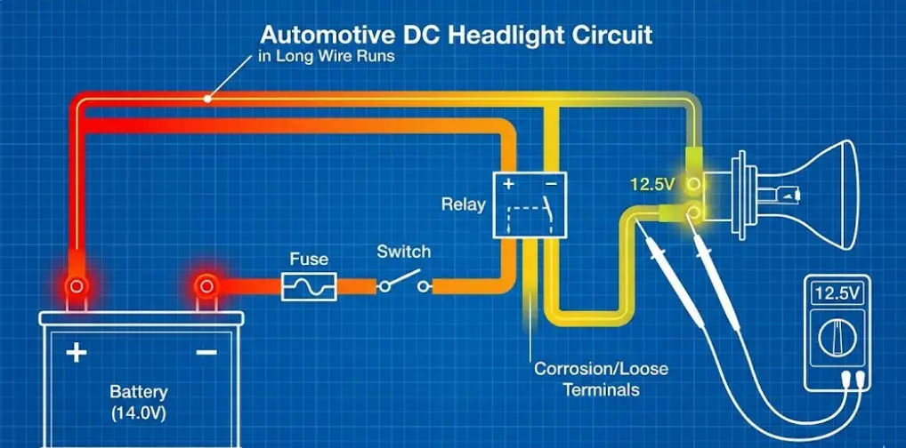
The relationship between voltage and light output (luminous flux) in a halogen bulb is exponential, not linear.
- The 95% Rule: A voltage drop of just 5% (e.g., from 13.5V to 12.8V) can result in a reduction of light output by nearly 17% to 20%.
- Factory Wiring Limitations: Manufacturers often use 18-gauge or 20-gauge wire to reduce cost and weight. Over the long wire runs found in full-size trucks (like the Chevy Silverado or Ford F-150), this internal wire resistance creates a natural voltage drop, resulting in factory headlights that are dimmer than the bulb's rated potential.
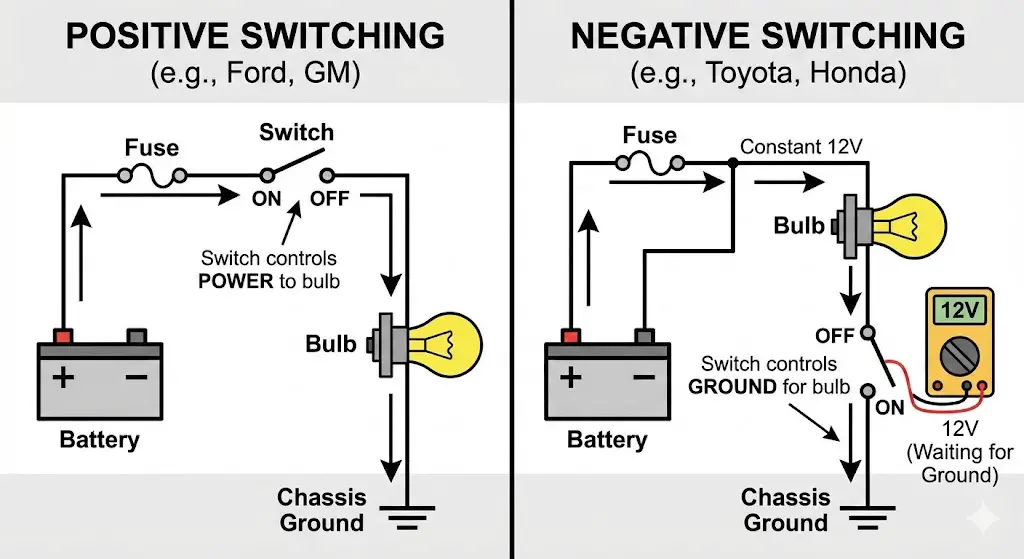
Switching Topologies: Positive vs. Negative
Understanding the switching logic is prerequisite to installing any aftermarket lighting accessories, such as light bars or LED upgrades.
Positive Switching (Standard)
Used predominantly by American and European manufacturers (Ford, GM, Ram, Jeep).
- Mechanism: The bulb has a permanent, unswitched connection to the Chassis Ground (-).
- Control: The headlight switch, relay, or Body Control Module (BCM) sends 12V+ Power to the bulb to illuminate it.
- Diagnostic Signature: When the lights are OFF, there is 0V at the positive pins. When ON, there is 12V+.
Negative Switching (Switched Ground)
Used predominantly by Japanese manufacturers (Toyota, some Nissan, older Honda).
- Mechanism: The bulb has a permanent, unswitched connection to 12V+ Battery Power (often shared between high and low filaments).
- Control: The headlight switch is located on the Ground side of the circuit. Turning the switch ON connects the circuit to the ground.
- Diagnostic Signature: When lights are OFF, a multimeter may read 12V+ on ALL pins of the headlight plug. This occurs because the voltage flows through the filament and "waits" at the open switch. This reading often confuses technicians, leading them to believe the ground is "hot".
- Implication: You cannot install a standard "high beam trigger" for driving lights by simply tapping the high beam wire, as it rests at 12V and drops to 0V when active. A polarity-inverting relay harness is required.
Global Headlight Bulb Standards and Pinout Configurations
In the absence of standardized wire coloring, pin position geometry is the only reliable method for identifying circuit functions. The following data synthesizes pinout configurations for the most common automotive bulbs.
The H4 (9003/HB2) Dual-Filament Architecture
The H4 bulb is a staple of the automotive industry, utilized in vehicles ranging from the 1980s Porsche 911 to the 2013 Toyota Tundra. It features a three-pronged base arranged in a "U" shape.
Confusion in Documentation:
Search data indicates significant confusion regarding H4 pinouts, with contradictory diagrams appearing online. This contradiction arises from the difference between Positive and Negative switched systems.
Table 1: H4 (9003) Pinout Configuration (Rear View of Bulb)
Orientation: Looking at the back of the bulb with the single alignment tab facing UP.
| Pin Position | Function (Standard/Pos-Switched) | Function (Toyota/Neg-Switched) |
| Left Vertical Pin | Ground (-) | Common Power (12V+) |
| Top Horizontal Pin | Low Beam (+) | Low Beam Ground |
| Right Vertical Pin | High Beam (+) | High Beam Ground |
Sources:
Technical Insight:
- Filament Position: The low beam filament in an H4 bulb is shielded by a small metal cup that directs light upward into the top half of the reflector (which projects it down onto the road). The high beam filament is unshielded.
- Grounding: In a standard setup (e.g., Chevy, Jeep), the Left Pin is the common ground. However, in a Toyota (e.g., Tacoma, Tundra), the Left Pin is the Common Positive 12V feed. This reversal is why simple "Plug-and-Play" LED harnesses often fail on Toyotas; the diodes block the reverse current flow.
The 9004 (HB1) vs. 9007 (HB5) Divergence
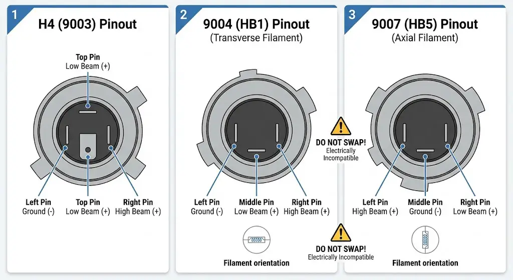
The 9004 and 9007 bulbs represent a significant engineering trap. Physically, they appear nearly identical: both have plastic bases, three pins, and similar locking collars. However, they are electrically incompatible.
Structural Differences:
- 9004 (HB1): Filaments are arranged transversely (horizontal across the vehicle axis).
- 9007 (HB5): Filaments are arranged axially (running parallel to the vehicle axis).
Table 2: 9004 vs. 9007 Pinout Comparison (Rear View of Bulb)
Orientation: Looking at the back of the bulb base.
| Pin Position | 9004 (HB1) Function | 9007 (HB5) Function |
| Left Pin | Ground (-) | High Beam (+) |
| Middle Pin | Low Beam (+) | Ground (-) |
| Right Pin | High Beam (+) | Low Beam (+) |
Sources:
The "Swap" Failure Mode:
Users frequently attempt to install 9007 bulbs in 9004 housings to gain wattage or "better light."
- Optic Failure: The reflector designed for a transverse filament (9004) cannot focus the light from an axial filament (9007), resulting in a scattered beam pattern that blinds oncoming drivers.
- Electrical Failure: If a 9007 bulb is plugged into a 9004 socket:
- The vehicle's Ground wire (Left slot) connects to the bulb's High Beam pin.
- The vehicle's Low Beam wire (Middle slot) connects to the bulb's Ground pin.
- Result: The circuit back-feeds through the filaments. Often, both filaments glow dimly at half-power, or the high beam indicator on the dash illuminates permanently. In high-current scenarios, this can melt the harness.
The H13 (9008) Compact Standard
The H13 (9008) is the standard for modern American trucks (Ford F-Series 2004-2014, Ram 1500 2009+). It features a very compact plastic base with three narrow pins.
Table 3: H13 (9008) Pinout Configuration (Front View of Connector)
Orientation: Looking into the female connector on the wiring harness.
| Pin Position | Function | Common Aftermarket Wire Color |
| Pin 1 (Top) | High Beam (+) | Yellow |
| Pin 2 (Middle) | Low Beam (+) | Brown |
| Pin 3 (Bottom) | Ground (-) | Black |
Sources:
Vulnerability: The H13 connector is notorious for resistive heating failure. The contact pins are significantly smaller than those on H4 or 9004 bulbs, providing less surface area for current transfer. Over time, the female terminals in the factory plug loosen, leading to arcing and melting.
Single-Beam Standards: 9005, 9006, and H11
Modern headlight assemblies (like those on the 2014+ Silverado and Tundra) separate low and high beam functions into dedicated bulbs.
Table 4: Single Beam Pinout and Keying
| Bulb Type | Function | Connector | Polarity Sensitive? | Keying Feature |
| 9005 (HB3) | High Beam | 2-Pin | No (Halogen) / Yes (LED) | Narrow top locking tab |
| 9006 (HB4) | Low Beam | 2-Pin | No (Halogen) / Yes (LED) | Wide top locking tab |
| H11 | Low/Fog | 2-Pin | No (Halogen) / Yes (LED) | Internal plastic ridge key |
H11 Polarity:
For H11 connectors, when looking at the bulb pins with the wide clip tab at the top:
- Left Pin: Positive (+)
- Right Pin: Negative (-)
- Note: Always verify this on the vehicle harness, as aftermarket pigtails may reverse wire colors (e.g., using black for positive).
Vehicle-Specific Wiring Architectures (The "Big Four")
While pinouts are standardized by bulb type, wire color coding is proprietary to each manufacturer and can change mid-generation. The following data is synthesized from factory service manuals and field reports.
Ford F-Series (F-150 & Super Duty)
Ford's wiring architecture has transitioned from simple analog switching to complex BCM-controlled Pulse Width Modulation (PWM).
Table 5: Ford F-150 Wiring Color Codes
| Function | 2004-2014 (H13 Analog) | 2015-2020 (Halogen/PWM) | Notes |
| Low Beam | Dark Blue/White or Dark Green/Orange | Blue/Green (Driver) / Blue/White (Pass) | Colors often differ Left vs. Right |
| High Beam | Light Green/Black | Gray/Brown (Driver) / Purple/Orange (Pass) | |
| Ground | Black or Black/Blue | Black/Yellow or Black/Green | Reliable chassis ground |
| Turn Signal | White/Blue | Blue/Green | Often acts as DRL on higher trims |
Sources:
The 2018+ Connector C1021:
For 2018+ F-150s with halogen headlights, the main interface is Connector C1021.
- Pin 6: Low Beam (Brown/Blue)
- Pin 2: High Beam (Gray/Brown)
- Pin 9 & 16: Ground
- Pin 3: Daytime Running Light (DRL) Feed (Gray/Blue) - Critical for switchback LED installation.
- Insight: The DRL signal on newer Fords is a PWM signal (pulsed voltage). Installing LEDs here without a capacitor/decoder will result in severe flickering or the BCM shutting down the circuit.
Chevrolet Silverado & GMC Sierra
GM trucks utilize a robust but complex fuse-block distribution system. Wire colors are generally consistent within generations but vary between Driver (LH) and Passenger (RH) sides.
Table 6: Chevy Silverado Wiring Color Codes (2007-2018)
| Function | Wire Color (Driver Side) | Wire Color (Passenger Side) |
| Low Beam | Yellow | Yellow (Often shared color) |
| High Beam | White | Light Green |
| Ground | Black | Black |
| DRL/Turn | Blue/White | Green/Violet |
Sources:
Technical Note: On 2014-2018 models using H11 low beams, the low beam power (Yellow) is BCM controlled. The BCM monitors current draw. If a bulb burns out, the BCM may stop sending voltage to that circuit until the key is cycled, complicating diagnosis. Technicians often mistake this "safety cutoff" for a blown fuse.
Ram Trucks (1500/2500/3500)
Ram trucks (2013+) possess the most sensitive CANBUS lighting monitoring system in the industry.
Table 7: Ram 1500 Wiring Color Codes (2013-2018)
| Function | Wire Color |
| Low Beam | White/Dark Blue |
| High Beam | White/Light Green |
| Ground | Black |
| Turn/Park | White/Yellow |
| Running Light | White/Brown (varies by trim) |
Sources:
The "Lamp Out" CANBUS Challenge:
The Ram Body Control Module (BCM) measures the resistance of the headlight circuit multiple times per second.
- Scenario: Installing an LED bulb (low resistance).
- Reaction: The BCM detects resistance outside the halogen range and cuts power to the circuit within 3-5 seconds to "protect" the system.
- Solution: Simple resistors are often insufficient. Ram trucks require robust CANBUS Decoders (often with both capacitors and resistors) or an OBDII programming change (using tools like AlphaOBD) to set the BCM to "LED Mode".
Toyota Tundra & Tacoma
Toyota trucks are the primary use case for Negative Switching logic, which fundamentally alters wiring requirements.
Table 8: Toyota Tundra Wiring Color Codes (2007-2020)
| Function | Wire Color | Polarity logic |
| Common Power | White/Black or Red/Yellow | Constant 12V+ (Do not Ground!) |
| Low Beam Trigger | Red/Green | Switched Ground (Connects to Chassis when ON) |
| High Beam Trigger | Red/Yellow | Switched Ground (Connects to Chassis when ON) |
Sources:
The Light Bar Integration Problem:
A common modification is wiring a light bar to trigger with the high beams.
- Standard Method: Tap the high beam wire (Red/Yellow) to pin 86 of a relay.
- Toyota Result: The light bar stays ON permanently or acts inverted.
- Why: The Red/Yellow wire rests at 12V+ when the lights are OFF (floating voltage).
- Correct Wiring: You must wire the relay to be triggered by ground. Connect Relay Pin 86 to Battery +12V, and Relay Pin 85 to the Toyota High Beam wire (Red/Yellow). When the high beams turn on, the Red/Yellow wire becomes a Ground, completing the relay circuit.
Pathology of Failure: Thermal and Electrical Breakdown
Analysis of search queries regarding "melted headlight sockets" reveals a widespread issue in automotive lighting maintenance.
The Mechanism of Connector Melting
Why do headlight plugs melt? The failure is rarely due to the bulb's radiant heat alone. It is a compound failure mode known as Resistive Heating.
- Spring Tension Loss: The female terminals inside the plastic plug rely on spring tension to grip the bulb's metal prongs. Over time, heat cycles cause the metal to fatigue and the plastic to warp, reducing clamping force.
- Resistance Spike: Lower clamping force reduces contact surface area. Resistance ($R$) increases.
- Thermal Runaway: Current ($I$) remains constant (or increases if voltage drops). Power dissipated as heat ($P = I^2R$) creates a localized hotspot at the terminal, often exceeding 300°F.
- Melting: Standard Nylon/ABS connectors melt between 250°F-280°F. The plastic deforms, further loosening the connection, until arcing occurs or the connection breaks.
Material Science: Plastic vs. Ceramic
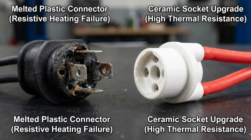
The definitive solution to melting connectors is upgrading the material of the interface.
Table 9: Connector Material Performance Comparison
| Feature | Standard OEM Plastic (Nylon/ABS) | Aftermarket Ceramic (Porcelain) |
| Melting Point | 250°F - 280°F (121°C - 138°C) | > 1000°F (537°C) for ceramic core |
| Thermal Conductivity | Low (Insulator - traps heat) | High (Dissipates heat) |
| Application | Standard 55W/65W Halogen | High Wattage (80W/100W) or Repair |
| Durability | Prone to brittleness over time | Extremely robust; wires usually silicone shielded |
Sources:
Recommendation: For any vehicle that has experienced a melted plug, or any vehicle running "performance" halogen bulbs (e.g., Sylvania SilverStar or off-road 100W bulbs), a Ceramic Socket Pigtail is the mandatory repair. Splicing in another plastic OEM socket will likely lead to a recurrence of the failure.
Diagnostic Protocols and Troubleshooting
Successful diagnosis relies on methodical testing rather than parts swapping.
Protocol: Diagnosing Dim or Yellow Headlights
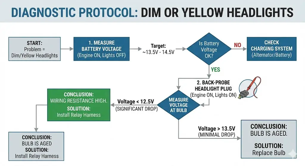
Theory: Dim lights are typically caused by Voltage Drop in the wiring harness, not bad bulbs.
Procedure:
- Baseline Voltage: Measure voltage at the battery terminals with the engine running (~14.0V).
- Load Voltage: Turn on the headlights. Back-probe the headlight connector (insert multimeter probes into the back of the plug while it is connected to the bulb).
- Measurement: Measure voltage across the Positive and Ground wires of the low beam.
- Analysis:
- Reading > 13.5V: Wiring is good. Bulb is likely aged (filament deposition on glass).
- Reading < 12.5V: Significant voltage drop (>1.5V). The factory wiring is too thin or there is corrosion in a switch/ground. Solution: Install a Headlight Relay Harness. This kit draws power directly from the battery via relays, using the factory wiring only as a low-current trigger. This often restores 1-2 Volts to the bulb, increasing brightness by 30%+.
Protocol: Identifying "Negative Switching"
Scenario: You are unsure if your vehicle (e.g., older Isuzu, Mitsubishi, Toyota) is negative switched.
Procedure:
- Turn Headlights OFF.
- Set Multimeter to DC Volts. Connect Black probe to Chassis Ground.
- Probe the three pins of the headlight socket.
- Positive Switched Result: 0V on all pins.
- Negative Switched Result: 12V on two or three pins. (Voltage is present but has nowhere to go because the ground switch is open).
Protocol: Troubleshooting "Flickering" LEDs
Scenario: New LED bulbs strobe or turn off after a few seconds (common in Ram/Ford).
Diagnosis: The vehicle's PWM (Pulse Width Modulation) or CANBUS monitoring is interfering.
Procedure:
- Engine OFF, Lights ON: Do they flicker? If No, but they flicker when Engine is ON, it is likely a PWM interference issue.
- Test: Install a "CANBUS Decoder" or "Anti-Flicker Capacitor" inline.
- Ford F-150 Specific: For 2015+ Fords, the DRL operates by pulsing the low beam at reduced duty cycle. LEDs cannot dim via PWM effectively; they strobe. You must disable the DRL via the dash menu or use a programmed decoder.
Modernization and Retrofit Engineering
Upgrading lighting systems requires careful integration to avoid blinding other drivers or melting wiring.
Relay Harness Integration
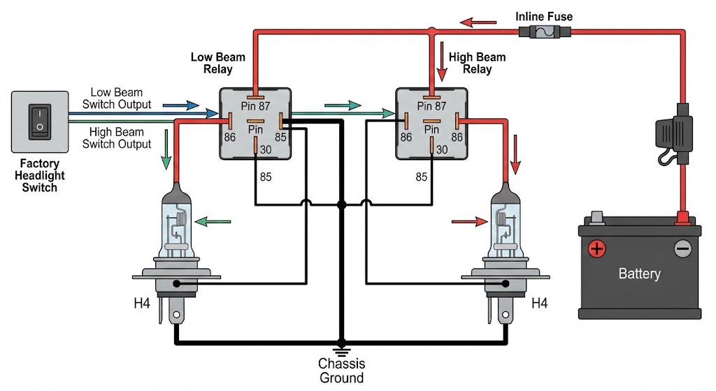
A relay harness is the most cost-effective upgrade for older vehicles.
- Components: Two relays (High/Low), inline fuse holder, heavy-gauge (12AWG or 14AWG) battery leads, ceramic headlight sockets.
- Logic: The factory headlight switch now carries only 0.1 Amps (to trigger the relay coil) instead of 10 Amps (to light the bulbs). This prevents the headlight switch from overheating—a common failure in older vehicles.
- Visual Aid:
- Battery (+) -> Relay Pin 30
- Chassis Ground -> Headlight Ground
- Factory Headlight Switch -> Relay Pin 86
- Relay Pin 85 -> Chassis Ground
- Relay Pin 87 -> New Headlight Bulb (+)
LED Polarity and Keying
Unlike halogen bulbs, LEDs are diodes—they only allow current to flow in one direction.
- The "Doesn't Light Up" Fix: If a new 9005/9006/H11 LED does not light up, unplug it, rotate the connector 180 degrees, and plug it back in.
- Toyota H4 LED Issue: On negative switched Toyotas, standard LED bulbs may not work because the "Common" pin on the LED is wired as Ground, but the car provides "Common Positive."
- Solution: Use a "Polarity Reversing Adapter" (often included with high-end kits or sold separately) that flips the wiring logic for the LED driver.
H4 to Projector Retrofits
When converting a vehicle from H4 halogen to a Bi-Xenon or Bi-LED projector:
- The "High Beam Stuck" Issue: The solenoid that drops the shield for high beam often requires a diode to prevent back-feeding current into the low beam circuit, which can keep the car running or cause dash lights to stay on. High-quality retrofit harnesses include a diode block to isolate these circuits.
Frequently Asked Questions
Q: What is the standard wire color for the headlight ground?
A: There is no universal standard.
- US Domestic (Ford/GM/Ram): Usually Black.
- Japanese (Toyota/Honda): Often White with Black Stripe (White/Black).
- European (DIN): Brown.
- Warning: Never assume Ground based on color. Always test for continuity to the chassis.
Q: Can I put a 100W bulb in my stock wiring harness? A: No. Stock wiring is typically rated for 55W (approx 4.5 Amps). A 100W bulb draws over 8 Amps. This ~80% increase in current will cause voltage drop (dimming the light) and excessive heat in the stock plastic connector, leading to melting. You must use a ceramic socket relay harness for 100W bulbs.
Q: Why does my high beam indicator stay on when I install LEDs in my Toyota? A: This is due to the negative switching architecture. The high beam indicator bulb is often wired in parallel with the headlight circuit. The low resistance of the LED driver changes the circuit balance, allowing ground to back-feed through the indicator bulb. A "CANBUS load resistor" or a specific negative-switching harness adapter is required to correct the dash light.
Q: What is the difference between 9005, 9005XS, and 9011 bulbs?
A:
- 9005 (HB3): Standard 65W High Beam. 90-degree connector.
- 9005XS: Straight connector (for tight spaces). Electrically identical.
- 9011 (HIR1): Halogen Infrared Reflective. Same base geometry (with minor tab trimming) but significantly brighter and more efficient. A common "stealth" upgrade for 9005 sockets.
Conclusion
The automotive headlight system is a dynamic interaction of electrical load, switching logic, and thermal management. As this report demonstrates, the wiring diagram is merely the starting point. The successful repair or modification of a headlight system requires a technician to identify the switching topology (Positive vs. Negative), respect the thermal limits of the connectors (Plastic vs. Ceramic), and navigate the complex monitoring systems (PWM/CANBUS) of modern vehicles. By adhering to the pinout data and diagnostic protocols outlined above, users can ensure safe, reliable, and high-performance illumination.

![How To Install In Channel Rain Guards [2026]](https://truckguider.com/wp-content/uploads/2026/03/featured-b43761fc-768x432.webp)

![Dodge Dakota Towing Capacity Guide: 1987-2011 Ratings [2026]](https://truckguider.com/wp-content/uploads/2026/03/dodge-dakota-tow-capacity-featured.webp)