E Construction Lifters on a Hemi: MDS Delete & Tray Specs

The notorious Hemi tick often signals catastrophic valvetrain damage caused by failing factory lifters. In Gen III Hemi engines, “E construction” lifters are heavy-duty, non-MDS hydraulic roller lifters engineered with reinforced roller axles and optimized oil metering to eliminate premature needle-bearing collapse and cam lobe wipeout.
Commonly adapted from factory Hellcat and high-output SRT platforms, these lifters serve as the benchmark upgrade for Multi-Displacement System deletes and performance engine builds. The following breakdown explores critical valvetrain tolerances, teardown specifications, alignment tray requirements, and camshaft inspection techniques needed to secure long-term reliability.
Understanding E Construction Lifters on a Hemi
Recommended Best Deal Products


Mopar Revision History: From Early Lifters to the AE Hellcat Spec
In the Gen III Hemi community, “E construction” lifters refer to factory-engineered hydraulic roller lifters produced under Mopar’s latest non-MDS production revisions. Chrysler originally deployed these heavy-duty components for extreme operating conditions, standardizing them in high-output applications like the supercharged 6.2L Hellcat and non-MDS 6.4L Apache platforms.
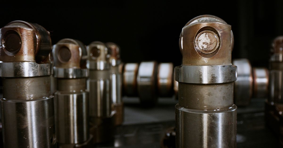
The “E” label stems from Mopar’s sequential part numbering progression. To eliminate internal weaknesses under high valve spring loads, Mopar continuously re-engineered the lifter assembly. Earlier factory components bearing AB and AC suffixes were phased out and replaced by updated iterations, culminating in the current AE and E part suffix.

Because early non-MDS and MDS lifters experienced higher rates of wear in passenger vehicles and Ram trucks, builders regard the AE revision as the gold-standard factory replacement. It offers an engineered OEM solution that cures longstanding valvetrain vulnerabilities in 5.7L and 6.4L engines without relying on aftermarket guesswork.
Cross-Platform Compatibility Across Gen III Engine Blocks
Despite substantial output differences across the modern Hemi engine family, Chrysler retained uniform valvetrain dimensions across its primary casting designs. Standard Gen III Hemi factory blocks share a standardized lifter bore diameter of 0.842 inches across all standard production years.
This dimensional consistency allows AE-suffix Hellcat lifters to drop directly into 5.7L, 6.1L, 6.2L, and 6.4L engine blocks without custom machine work. Whether retrofitting an early 6.1L SRT-8, refreshing a 6.4L Apache, or updating an everyday 5.7L block, the shared 0.842-inch lifter bore guarantees precise cross-platform mechanical fitment.
Key Engineering Details of E Construction Lifters on a Hemi
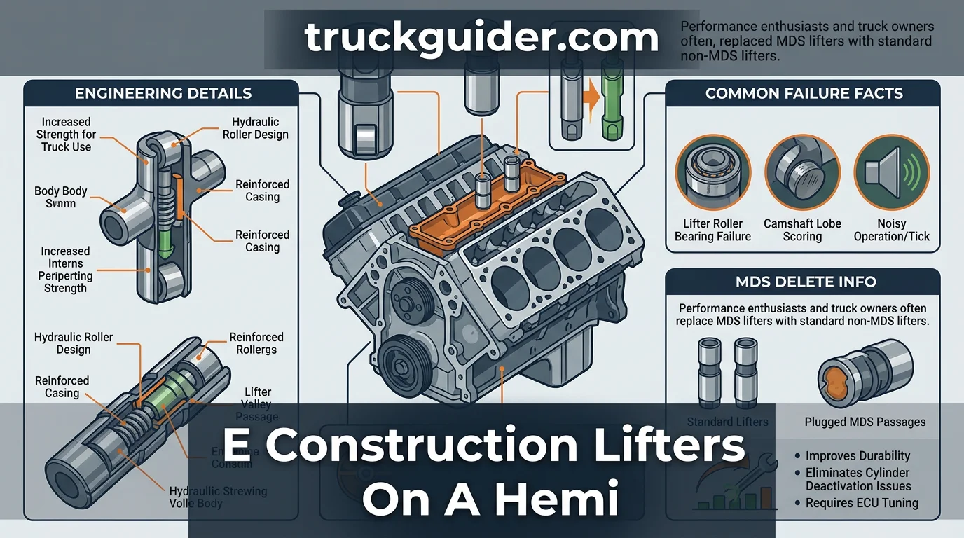
The E-revision lifter is built on an industry-standard 0.842-inch outer diameter (OD) body precision-machined from case-hardened steel. Unlike factory Multi-Displacement System (MDS) lifters that rely on split inner sleeves and deactivation pins, the E-lifter utilizes a non-MDS solid body design that completely prevents pin de-lash collapse under high valvetrain loads.
The 0.842-inch OD solid wall eliminates oil bypass cavities found in MDS hardware, ensuring complete structural rigidity around the hydraulic chamber under high cylinder pressures.
Reinforced Axle Pin and Needle Bearing Assembly
At the base of the lifter, an upgraded roller wheel rotates on high-grade needle bearings supported by a through-hardened axle pin. This internal roller package is engineered to resist severe shear forces, high spring pressures, and oil thinning caused by elevated combustion temperatures.
Design revisions directly address historical wear points. Compared to early standard 5.7L lifters, revision E parts feature improved orbital pin swaging for superior lateral retention, alongside tighter needle bearing race tolerances that prevent needle skewing and binding within the roller channel.
Hydraulic Plunger Valving and Pushrod Metering Seat
Inside the lifter reservoir, a high-tolerance hydraulic plunger works in tandem with a micro-polished check ball and an internal expansion spring. This assembly meters oil into the high-pressure chamber, providing rapid lash recovery and maintaining consistent zero-lash valvetrain geometry across the entire RPM range.
Engine oil enters through an external oil band groove and flows past an internal metering plate situated below the pushrod seat. This seat directs a metered, pressurized stream of oil up through the hollow pushrod tube, delivering constant lubrication directly to the rocker arms and valve tips.
Why Stock Hemi Lifters Fail: Needle Bearings and Cam Wipeout Facts
Recommended Best Deal Products


The Mechanics of Needle Bearing Seizure at Idle
At standard idle speeds around 500 to 650 RPM, the Hemi oil pump produces lower system pressure and reduced oil volume at the top of the block. Because stock lifter rollers depend largely on splash lubrication and oil runoff rather than a dedicated high-pressure feed, low-RPM operation starves the tiny internal needle bearings of a critical hydrodynamic cushion.
This lubrication deficit compounds significantly under extended oil change intervals, where broken-down additive packs and suspended particulate accelerate abrasive wear. For example, extended municipal or police idle hours routinely cause needle bearing pin flat-spotting, with failures occurring predominantly on high-load positions such as cylinder 3 or 5.
As the tiny needle bearings run dry, friction generates intense localized heat along the lifter roller axle pin. The needles begin to skate rather than roll, galling the pin surface and ultimately wedging together until the entire bearing assembly locks up solid.
From Audible Hemi Tick to Ground-Down Camshaft Lobes
Bearing seizure immediately destabilizes valvetrain geometry. As the needle bearings collapse, internal clearance expands beyond what the hydraulic mechanism can compensate for, causing total lash collapse. The pushrod and rocker arm begin hammering against the collapsed lifter, generating the rhythmic, metallic chatter colloquially recognized as the “Hemi tick.”
Once the roller ceases to spin, it acts like a stationary steel chisel dragging across the spinning camshaft. The hardened camshaft lobe rapidly grinds a flat spot onto the frozen roller, stripping away the case-hardened surface layer of both components and causing severe lobe scoring.
Lifter roller bearing failure grinds directly into the camshaft lobe, requiring both the cam and lifters to be replaced together. Once metal-on-metal cam wipeout begins, the lobe profile is permanently destroyed, shedding metallic debris through the oiling circuit and making paired component replacement mandatory.
MDS Delete Guide: Upgrading to E Construction Lifters on a Hemi
Deleting the Multi-Displacement System (MDS) is the primary reason enthusiasts install non-collapsing E-construction lifters. While factory MDS lifters utilize oil-controlled locking pins to deactivate cylinders for fuel economy, converting to rigid E-construction units eliminates these mechanical weak points entirely to maximize engine longevity.
PCM Tuning and Solenoid Block-Off Plug Requirements
Converting from factory MDS lifters to non-MDS upgraded lifters requires disabling MDS in the engine control module (PCM) tune. Without software recalibration, the PCM attempts to engage cylinder deactivation cycles, triggering diagnostic trouble codes (DTCs), an illuminated check engine light, and immediate engine limp mode.
For example, completing this upgrade on a Ram 1500 5.7L requires installing four MDS valley plugs (part # 53032221AA) alongside an unlocked PCM flash. The physical conversion occurs beneath the intake manifold within the engine valley.
You must remove the four factory variable displacement solenoids and install the O-ring-equipped block-off plugs in their place. These plugs seal the high-pressure oil passages, ensuring full engine oil pressure routes directly to the lifter bores rather than venting into the crankcase.
Non-MDS Camshaft Selection to Match Upgraded Lifters
A non-MDS camshaft profile is a mandatory requirement when converting a factory MDS engine to E-construction lifters. Factory MDS camshafts feature uneven base circle dimensions and distinct ramp rates on cylinders 1, 4, 6, and 7 to accommodate the collapsible lifter design.
Installing standard, solid-body E-construction lifters on an OEM MDS camshaft causes severe valvetrain geometry mismatches, improper lifter preload, and valve float. Swapping to a factory non-MDS profile (such as a 6.4L manual camshaft) or a dedicated performance grind provides uniform lobe geometry across all sixteen valves.
Comparing E Construction Lifters on a Hemi vs Stock and Aftermarket
Recommended Best Deal Products


Every Gen III Hemi lifter configuration shares a standard 0.842-inch bore compatibility. Despite this identical sizing, dramatic differences exist in internal valving, dynamic stability, and overall design between factory components and high-performance alternatives.
Stock collapsible MDS lifters rely on spring-loaded locking pins to deactivate cylinders. These internal locking mechanisms introduce dynamic instability at higher engine speeds, making them prone to failure under increased spring loads and aggressive cam ramps.
How to Read This Comparison
The table displays mechanical constraints across factory, upgraded OEM, and competition valvetrain components. Bore diameter is universally verified at 0.842 inches to confirm drop-in block fitment across modern 5.7L, 6.4L, and 6.2L engine blocks without machining.
The RPM Ceiling indicates safe rotational speed before dynamic instability occurs. Bleed-down control defines how well internal oil pressure resists hydraulic collapse against stiff valve springs; precision tolerances maintain valve timing at high lift.
Maintenance defines user involvement over the engine’s service life. Factory and upgraded hydraulic rollers provide automatic zero-lash operation, while solid roller designs omit hydraulic cushions, forcing builders to manually set and inspect lash with feeler gauges periodically.
Premium aftermarket options take valvetrain control a step further. For example, the Johnson 2110R utilizes billet tool steel bodies with tight hydraulic bleed-down tolerances, maintaining plunger rigidity under severe spring pressures and high engine speeds.
Mechanical solid roller setups offer the absolute highest RPM potential by removing hydraulic fluid entirely. However, solid roller lifters are unsuited for street engines due to lack of hydraulic self-adjustment, requiring frequent tear-downs, valve lash adjustments, and elevated needle bearing monitoring.
For daily street machines and moderate performance builds, Mopar E-construction lifters provide the optimal balance. They eliminate the MDS failure point, deliver stable 6,500+ RPM capability, and bypass the high purchase cost of billet units or the labor-intensive upkeep of mechanical rollers.
Cylinder Head Removal Insights and Teardown Requirements
Why Gen III Hemi Architecture Mandates Head Removal
Unlike traditional domestic pushrod V8s with open valley lifter access, the Gen III architecture overhangs the lifter bores directly beneath the deck surface. Cylinder heads must be completely removed to access and replace lifters on all Gen III Hemi engines.
During the initial teardown, inspect each pushrod on a flat surface plate or glass to verify straightness. Examine the rocker shaft assemblies and rocker arm roller tips for heat scoring, galling, or excessive lateral play before tagging their exact positions.
📋
Teardown Sequence
Remove the upper intake manifold, fuel rails, ignition coils, and valve covers. Loosen rocker shaft bolts evenly in reverse torque order to extract the rocker assemblies and pushrods.
Drain engine coolant completely. Unbolt the exhaust manifolds or headers from the cylinder heads, disconnect the ground straps, and detach the engine wire harness brackets clear of the workspace.
Loosen the cylinder head bolts starting from the outer bolts inward. Lift the cylinder heads cleanly off the block alignment dowels to uncover the lifters seated within the engine block bores.
Single-Use Fasteners and Gaskets Required for Reassembly
Factory cylinder head fasteners are torque-to-yield (TTY) bolts engineered to stretch permanently to achieve proper clamping load. These fasteners cannot be reused under any circumstances; new replacement bolts and multi-layer steel (MLS) head gaskets are strictly required for reassembly.
For 5.7L and 6.4L Hemi heads, tighten the new M12 bolts from the center outward in a circular pattern: initial pass to 25 ft-lbs (34 Nm), second pass to 40 ft-lbs (54 Nm), followed by a 90-degree angle turn. Finally, torque the smaller top M8 bolts to 15 ft-lbs (20 Nm), followed by 25 ft-lbs (34 Nm).
Plastic Lifter Alignment Trays and Essential Hardware Info
The Function of Lifter Yokes in Preventing Roller Rotation
Hydraulic roller lifters rely on plastic alignment trays, often called lifter yokes or guide trays, to maintain precise radial positioning. Because roller lifters must track squarely against the camshaft lobes, their bodies feature flat sides that drop directly into matching channels inside each tray.
This flat-sided design locks the lifter in place, preventing it from spinning inside the lifter bore. Unlike traditional flat-tappet designs that rotate to distribute wear, a roller lifter must remain parallel to the cam lobe surface at all times to roll smoothly across the profile.
Heat Cycling and Plastic Fatigue: Why Reuse Causes Immediate Failure
Continuous engine heat cycling degrades the composite polymer used in lifter guides over time. The material becomes brittle, prone to stress fractures, and warps. As the alignment walls spread apart or crack, the tray loses its tight factory tolerances.
If worn trays allow a lifter to twist even slightly off-center, the edge of the roller wheel digs directly into the camshaft lobe. This angular contact rapidly strips the lobe surface, tears up the lifter wheel, and dumps metal debris directly into the engine oil supply.
Never reuse plastic lifter trays during an engine refresh or lifter replacement. A brand-new set of four OEM Mopar alignment trays features dedicated front and rear orientations and costs under $50, serving as essential, cheap insurance against catastrophic valvetrain failure.
Critical Valvetrain Pitfalls and Camshaft Inspection Summary
Inspecting Cam Lobes for Micro-Scoring and Uneven Wear
Installing new lifters onto a camshaft that already has lobe wear or scoring from previous lifter failure guarantees immediate valvetrain damage. Even if a lobe appears serviceable to the naked eye, microscopic surface imperfections will chew through the fresh E-lifter rollers in short order.
Carefully inspect each lobe under bright, angled lighting and optical magnification. If you detect hairline grooves, flat spots, or uneven taper wear across the contact path, the case-hardened surface layer is compromised, making an immediate camshaft replacement mandatory.
Flushing Metal Contamination from the Oil Pan and Galleries
When a factory lifter fails, needle bearing debris disperses throughout the lubrication circuit. Metal shavings from a collapsed roller bearing circulate through the engine oil, necessitating an oil system flush and oil pan inspection to protect the oil pump, main oil galleries, and rod bearings.
Drop the oil pan to scrub settled grit and clean the oil pickup tube screen. Gauge the extent of internal contamination by checking the magnetic drain plug and cutting open the oil filter to inspect for needle bearing flake contamination before installing your replacement components.
Ignoring low-RPM idle time or poor oil change intervals is widely linked to accelerated roller bearing wear on Hemi platforms. To protect new E-lifters, minimize prolonged idling, utilize high-detergent oils with adequate zinc and phosphorus (ZDDP) content, and perform regular lubrication system flushes.
Key Takeaways
-
✓
E construction lifters replace failure-prone MDS lifters with solid-body hydraulic roller units featuring strengthened axle pins. -
✓
Lifter roller failure stems from oil starvation at idle and needle bearing breakdown, leading directly to camshaft lobe scoring. -
✓
Upgrading requires complete cylinder head removal, fresh head bolts, new gaskets, and non-MDS lifter alignment trays. -
✓
MDS delete PCM tuning is mandatory when retrofitting E construction lifters to deactivate cylinder deactivation error codes. -
✓
Thorough camshaft inspection is non-negotiable, as reusing scored cam lobes will instantly destroy newly installed lifters.
❓ Frequently Asked Questions
1
What are E construction lifters on a Hemi?
E construction lifters are updated Mopar non-MDS hydraulic roller lifters featuring revised engineering details. Identified by their casting revisions, they incorporate stronger internal valving and superior roller needle bearings to eliminate the premature failure modes common to factory MDS-equipped 5.7L and 6.4L Hemi engines.
2
How do E construction lifters prevent Hemi cam wipeout?
Unlike MDS lifters that rely on locking pins and complex oil passages, non-MDS E construction units maintain continuous, stable roller contact on the camshaft lobe. The reinforced needle bearings tolerate idle oil pressure drops far better, preventing roller seizure that grinds down cam lobes into metal debris.
3
Why is cylinder head removal required to install these lifters?
Gen III Hemi architecture positions the lifters directly beneath the cylinder heads within dedicated block valley bores. Because the lifters are secured inside plastic alignment trays that cannot clear the lower edge of the head casting, complete cylinder head removal is physically mandatory for replacement.
4
What parts are needed alongside an E construction lifter upgrade?
A proper installation requires four non-MDS plastic alignment trays, new cylinder head gaskets, torque-to-yield head bolts, and MDS block-off plugs. Furthermore, you need an unlocked PCM tune to disable MDS functions, along with a compatible non-MDS camshaft profile to match the solid roller design.
5
Can I install E construction lifters on a stock MDS camshaft?
While physically possible, installing non-MDS lifters on an MDS camshaft is not recommended. MDS camshafts feature different lobe base circles between active and inactive cylinders. For long-term reliability and proper valvetrain preload, pair E construction lifters with a dedicated non-MDS performance or OEM camshaft.
6
What is the difference between MDS and non-MDS Hellcat lifters?
MDS lifters feature hydraulic locking pins and collapsible internal sleeves that deactivate cylinders 1, 4, 6, and 7. Non-MDS Hellcat (‘E’ construction) lifters feature a solid, rigid outer body, reinforced roller axle pins, and heavier-duty needle bearings designed for sustained high RPM and continuous valve lift without deactivation mechanisms.

![2012 Ram 1500 5.7 Oil Capacity & Type: Specs & Fitment Guide [2026]](https://truckguider.com/wp-content/uploads/2026/03/2012-ram-1500-5-7-oil-capacity-featured.webp)