Ford F150 Wiring Harness Diagram: 2026 Troubleshooting Guide

The Ford F150 wiring harness follows a standardized color scheme where black indicates the primary ground wire, while red or yellow typically identifies the hot wire. Always verify specific pin assignments using a multimeter at the connector block located behind the kick panel or near the trailer tow module for precise voltage readings.
📌 Key Takeaways
- Most F150 chassis grounds utilize a 10-gauge black wire to ensure stable current flow to the ECU.
- Always cross-reference the pin assignment map against the specific harness part number stamped on the cable loom.
- Maintain a minimum 12-volt potential at the hot wire terminal; drops below 10.5V indicate excessive circuit resistance.
- The most common failure point is corrosion at the trailer tow connector interface, often caused by moisture intrusion.
- Consult a certified technician if the wiring harness exhibits signs of heat damage or melted insulation, as this suggests a short requiring professional diagnostic tools.
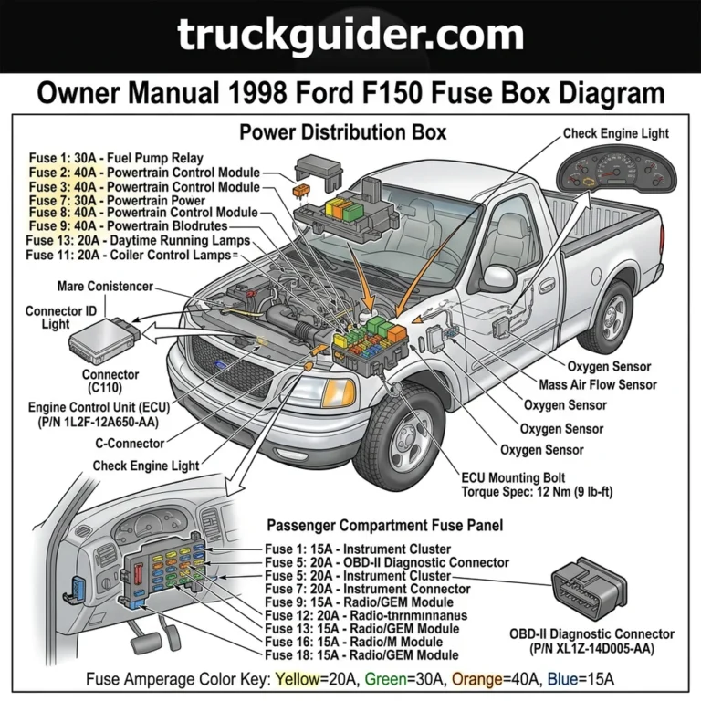
Modern Ford F-150 electrical systems represent a complex architecture of integrated circuits, multiplexed data lines, and high-current power distribution nodes. Navigating a Ford F-150 wiring harness diagram requires more than a basic understanding of voltage and continuity; it necessitates a precise grasp of how the Engine Control Module (ECM) and Body Control Module (BCM) communicate across the controller area network (CAN bus). Whether you are diagnosing a parasitic draw in the chassis harness or tracing a failure within the power distribution center, access to accurate, VIN-specific technical documentation is mandatory. This guide serves as a technical reference for identifying wire color codes, understanding terminal block pin assignments, and executing safe electrical repairs on your vehicle’s critical harness assemblies.


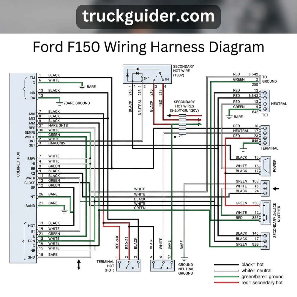
Mastering the Ford F-150 Wiring Harness Diagram Architecture
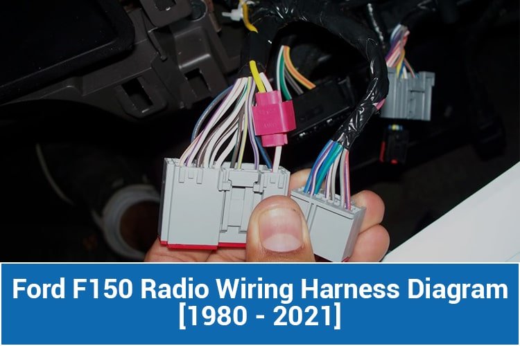
The electrical architecture of the F-150 has evolved significantly across model years, shifting from traditional hard-wired relays to sophisticated solid-state power management. Understanding the Ford F-150 wiring harness diagram requires compartmentalizing the vehicle into four primary sub-systems. The ECM harness acts as the nervous system for powertrain management, containing shielded twisted-pair cables designed to mitigate electromagnetic interference, which could otherwise corrupt sensor data. When inspecting this section, you must maintain the integrity of the insulation, as any breach can lead to erratic engine performance or “limp home” modes triggered by noise on the signal lines.
The Body Control Module (BCM) wiring manages auxiliary power, lighting, and convenience features. This section of the harness is highly sensitive to moisture ingress, particularly near the kick panels. The chassis harness connects the front power distribution center to the rear lighting and fuel pump modules, often running along the frame rails. These wires are subjected to environmental extremes, making the factory-applied protective shielding critical for longevity.
Finally, the power distribution center serves as the main junction for the vehicle’s electrical load. It utilizes various terminal block designs to secure high-amperage connections. When reviewing your Ford F-150 wiring harness diagram, observe the distinction between constant battery voltage circuits and ignition-switched power. The grounding points located on the chassis are as significant as the hot wire feeds; a high-resistance ground path is the most common cause of seemingly unsolvable electronic gremlins in late-model Ford trucks. Always verify your specific diagram against the vehicle’s build date and engine configuration, as mid-year production changes are common in the F-150 platform.
Standard Ford F-150 Wiring Harness Diagram Color Codes

Standardization in automotive electronics allows technicians to trace circuits effectively. While Ford uses a sophisticated internal indexing system, the following table summarizes the universal conventions found within a standard Ford F-150 wiring harness diagram.
| Circuit Function | Standard Color Code | Typical Gauge |
|---|---|---|
| Constant Battery (Hot Wire) | Red / Yellow Stripe | 10-12 AWG |
| Chassis Ground | Black / Light Green | 10-14 AWG |
| Ignition Switched Power | Yellow / Red Stripe | 14-16 AWG |
| CAN Bus High | White / Blue Stripe | 20-22 AWG |
| CAN Bus Low | Blue / White Stripe | 20-22 AWG |
When documenting your findings during a repair, always cross-reference the color code with the pin assignment located at the terminal block. Note that wire gauge varies based on the current load requirements of the specific circuit. Using an undersized replacement wire—even if the color matches—can lead to excessive voltage drop or, in high-amperage scenarios, insulation melting and electrical fires.
How to Use a Ford F-150 Wiring Harness Diagram for Repairs
Effective troubleshooting requires a disciplined methodology. Begin by isolating the suspected circuit using the relevant Ford F-150 wiring harness diagram. Never attempt to “back-probe” sensitive CAN bus wiring with standard metallic tools, as this can damage the terminal plating and introduce future corrosion points. Instead, use specialized T-pins that are specifically designed for small-gauge automotive connectors.


When measuring voltage across a suspected faulty circuit, a reading within 0.5V of battery potential is generally considered acceptable for most DC accessories. For logic signals (CAN bus), use a digital oscilloscope to verify wave-form integrity rather than a standard DMM.
Follow these steps for systematic repair:
1. Verify the specific circuit by matching the pin assignment number printed on the plastic connector housing to the pin-out chart in your Ford F-150 wiring harness diagram.
2. Utilize a digital multimeter (DMM) set to the lowest resistance scale to check for continuity between the suspected terminal block point and the chassis ground.
3. If an open circuit is identified, perform a wiggle test on the harness while monitoring for resistance spikes, which indicates an internal conductor fracture.
4. When replacing a wire segment, ensure you use the identical wire gauge and heat-shrink butt connectors to maintain environmental sealing.
5. Apply a dielectric grease to the terminals upon reconnection to prevent oxidation—a common failure point in Ford truck harnesses exposed to salt and road debris.
Common Ford F-150 Wiring Harness Diagram Troubleshoot & Pitfalls
Even with an accurate Ford F-150 wiring harness diagram, technicians often encounter obstacles stemming from the truck’s multiplexed signal architecture. The most frequent issue is misdiagnosing a communication error as a component failure.
CAN Bus Interference: Ford F-150 systems are highly sensitive to impedance changes. If you add aftermarket accessories, ensure they are spliced correctly. An improperly soldered joint can create enough signal reflection to crash the entire bus, causing multiple modules to go offline simultaneously.
Corrosion in Terminal Blocks: The terminal block is the most common failure point for intermittent electrical issues. Over time, moisture causes green oxidation. Always inspect the pins for signs of discoloration; if present, the terminal must be replaced, as cleaning only provides a temporary fix.
Voltage Drop in Grounding Straps: Many F-150 owners overlook the primary ground straps connecting the engine block to the chassis. If the diagram indicates a shared ground for your malfunctioning components, test the resistance between the ground point and the battery negative terminal. A reading exceeding 0.1 ohms indicates a compromised ground that will cause “ghost” electrical faults.
Short-to-Ground Detection: Using a standard test light is discouraged on modern F-150s because the high current draw can damage delicate solid-state drivers within the BCM. Always use a low-amperage LED test light or a DMM with high input impedance.
* Wire Gauge Mismatch: Replacing a factory wire with one of a smaller diameter increases resistance. In circuits powering critical engine sensors, this added resistance will skew the data reaching the ECM, leading to false “Check Engine” light triggers.
Ford F-150 Wiring Harness Diagram Questions Answered
How do I find the correct wiring diagram for my specific truck model year?
You must use the vehicle identification number (VIN) to access the specific “as-built” electrical configuration. Manufacturers often update harness layouts mid-production. Always search for documentation based on the production date found on the driver-side door jamb sticker rather than the model year alone.


What is the best way to trace a short-to-ground in a main harness?
The most efficient method is to disconnect the module at the end of the circuit and test for continuity to ground at the source. If the short persists, section the harness at the major junction points identified in your Ford F-150 wiring harness diagram. By isolating the harness into smaller segments, you can narrow the search to a specific foot of cabling.
Why is my terminal block melting even though the fuse didn’t blow?
This is a classic sign of high-resistance heating. Corrosion at the terminal pin creates resistance, which generates heat as current flows through the connection. This heat is localized at the connection point and will melt the plastic housing long before the heat reaches the fuse to trigger a blow, emphasizing the need for dielectric protection.
Can I bridge a broken wire with a thicker gauge wire?
While you can generally use a larger gauge wire without harm, you must be careful at the terminal connection. Forcing a thicker wire into a terminal designed for a smaller gauge often leads to poor crimps and mechanical stress, which will lead to a repeat failure within a few months of service. Always use the original equipment specified gauge.
Step-by-Step Guide to Understanding the Ford F150 Wiring Harness Diagram
Identify – Locate the specific wiring harness connector and verify the part number against your truck’s specific build date.
Locate – Access the terminal block by removing the interior trim panels or plastic shielding near the firewall to reach the harness junction.
Reference – Cross-check the wire color code and pin assignment from your diagram to the actual wire positions on the connector.


Connect/Route – Secure the harness using factory-style clips and ensure all connections are tight, using dielectric grease to prevent corrosion.
Verify – Use a digital multimeter to check for 12V power on the hot wire and continuity on the ground wire before applying full system load.
Troubleshoot – If devices fail to initialize, re-check the pin assignment alignment and inspect the harness for any signs of pinched wires or loose pins.