How To Fix Electronic Throttle Control Issues [2026]
A sudden loss of engine power accompanied by a flashing lightning bolt icon on your dashboard can turn a routine commute into a high-stress emergency. Modern Electronic Throttle Control (ETC) systems replace traditional mechanical cables with complex sensors and high-torque motors; when these components fail, the vehicle often enters a restrictive ‘limp mode,’ leaving drivers struggling with stalling, surging, or no throttle response. This article provides a technical guide to diagnosing ETC faults using OBD-II data, performing multimeter tests on sensors, cleaning the throttle bore, and executing the critical relearn procedures necessary to restore vehicle drivability and safety.
Section 1: Diagnosing Electronic Throttle Control Failure with OBD-II Codes
The first step in any modern ETC repair is to debug the system using a professional-grade OBD-II scanner. Because the system is “drive-by-wire,” the Engine Control Module (ECM) constantly monitors the relationship between the driver’s foot and the actual position of the butterfly valve. When a discrepancy occurs, the ECM triggers a Diagnostic Trouble Code (DTC) to resolve the ambiguity of why the engine isn’t responding as expected.
Interpreting Critical ETC Codes
Common codes ranging from P2100 to P2111 specifically pinpoint throttle actuator control motor circuit issues. However, the nuance lies in the differentiation between a sensor error and a performance error. For instance, P2135 (TPS Voltage Correlation) indicates that the two sensors monitoring the throttle position disagree with each other, suggesting an electrical failure within the sensor housing. Conversely, P2101 (Control Motor Range/Performance) often means the ECM told the motor to move, but the physical butterfly valve didn’t reach the target, likely due to a mechanical obstruction or a failing motor.
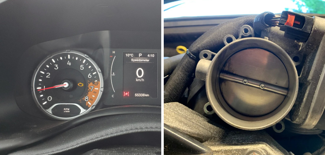
When the ECM detects a P2110 code, it enters ‘Limp Home Mode.’ This safety state limits engine speed to approximately 1500–2000 RPM and disables the accelerator pedal’s authority to prevent a runaway acceleration event. If you see a flashing ‘lightning bolt’ symbol, do not attempt to clear the code and drive at highway speeds until the root cause is identified.
Wiring and Connector Integrity
Before condemning the throttle body itself, a thorough visual inspection of the wiring harness is mandatory. The ETC system relies on low-voltage signals that are highly sensitive to resistance. Check the 6-pin or 8-pin connector for signs of corrosion, green oxidation, or “backed-out” pins where the wire has physically pulled away from the internal terminal. Intermittent signal loss is frequently traced back to harness fraying near the engine cover where heat and vibration are most intense.
By The Numbers
Issues caused by wiring/connectors
Primary Actuator Circuit Code
Section 2: Troubleshoot Throttle Body Performance and Carbon Accumulation
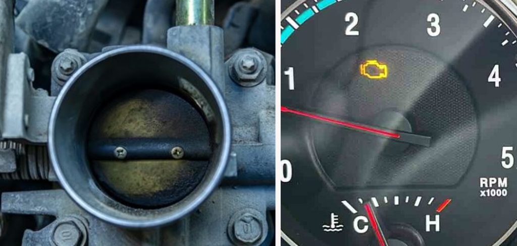
Many drivers assume a ‘lightning bolt’ light means the part is dead, but often the solution is a deep cleaning. Over time, oil blow-by from the Positive Crankcase Ventilation (PCV) system mixes with incoming dust to create “coking”—a sticky, black carbon residue that accumulates around the edges of the butterfly plate. This residue creates physical resistance, preventing the motor from achieving the precise idle angles commanded by the ECM.
The 1mm Threshold
Precision is everything in ETC systems. Accumulation of just 1mm of carbon around the throttle plate circumference can reduce idle airflow by up to 15%. When this happens, the ECM tries to compensate by opening the plate further. Eventually, the “learned” compensation value hits a limit, and the vehicle begins to experience a surging idle or a complete stall when coming to a stop.
Safe Cleaning Procedures
To diagnose if carbon is the culprit, remove the air intake ducting and inspect the bore. If you see a ring of black sludge where the butterfly valve meets the housing, cleaning is required. However, you must use a dedicated Electronic Throttle Body Cleaner. Generic brake cleaners or harsh solvents can strip the delicate molybdenum coating on the bore, which is designed to prevent carbon adhesion and ensure smooth movement.
On many modern brushless motor systems (common in German and some late-model American vehicles), forcing the throttle plate open by hand can strip the internal plastic gears. Instead, have an assistant hold the accelerator pedal down with the Ignition On, Engine Off to electronically open the valve for cleaning access.
Section 3: Testing the Accelerator Pedal Position and Throttle Position Sensors
When cleaning doesn’t resolve the issue, the troubleshoot process moves to the sensors. The ETC system relies on two sets of potentiometers: the Accelerator Pedal Position (APP) sensor (at your foot) and the Throttle Position Sensor (TPS) (on the throttle body). These sensors use a 5-volt reference signal from the ECM to communicate position.
The Multi-Signal Redundancy Test
Modern systems use dual sensors for redundancy. Typically, Signal 1 and Signal 2 work in an inverse relationship. For example, as Signal A goes from 0.5V at idle to 4.5V at wide-open throttle (WOT), Signal B might go from 4.5V down to 0.5V. Using a digital multimeter, you can perform a “sweep test” by slowly depressing the pedal. You are looking for “dead spots”—sudden drops or spikes in voltage. If the correlation between these two signals exceeds a 0.5-volt threshold, the ECM will immediately trigger a Malfunction Indicator Lamp (MIL).
Analyzing Freeze Frame Data
A seasoned technician never ignores the freeze frame data. This is a “snapshot” of the engine conditions at the exact moment the fault occurred. If the freeze frame shows the pedal was at 20% but the throttle angle was 0%, you have effectively narrowed the cause down to the actuator side of the system, rather than the command side.
Section 4: How to Resolve Calibration Errors via Throttle Relearn Procedures
The most overlooked workaround for ETC issues is the relearn procedure. Because the ECM learns to compensate for carbon buildup over thousands of miles, cleaning the throttle body—or disconnecting the battery—can leave the ECM with “stale” data. It expects a certain amount of resistance or air gap that no longer exists, resulting in a high idle or a recurring P0507 code.
📋
Step-by-Step Relearn Guide
Ensure the engine coolant temperature is between 160°F and 200°F. Turn off all electrical loads, including headlights, AC, and the radio.
For many GM and Nissan vehicles, this involves a timed “pedal dance” or using a scan tool to select ‘Idle Air Volume Learn.’ Follow the specific manufacturer timing down to the second.
Watch the idle RPM. It should stabilize within ±50 RPM of the target. If the relearn fails, check for vacuum leaks or a faulty thermostat preventing proper operating temp.
Approximately 25% of ‘faulty’ throttle bodies replaced are actually functional components that simply required a proper software relearn procedure. Before spending hundreds on parts, always attempt a recalibration after cleaning or battery maintenance.
Section 5: Replacing the Electronic Throttle Body Assembly
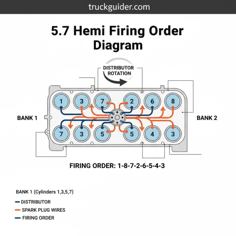
If your diagnose process leads to internal motor failure—often indicated by a loud clicking noise upon ignition or stripped plastic gears—replacement is the only permanent repair. This is common on engines like the 5.3L Vortec, where the internal nylon gears can crack under the stress of high-torque demands.
Installation Best Practices
When installing the new unit, always replace the throttle body gasket or O-ring. Reusing an old, flattened gasket is a recipe for a vacuum leak, which will cause a high idle and lean-burn codes (P0171/P0174). Ensure the mounting surface is pristine. If you are mounting to a plastic intake manifold, use a “star pattern” tightening sequence and adhere strictly to torque specifications (usually 89–120 inch-pounds) to prevent warping the flange.
✅ Pros of Replacement
- Eliminates intermittent electronic glitches
- Restores factory-spec idle stability
- Includes new, calibrated TPS sensors
- Solves mechanical gear-stripping issues
❌ Cons of Replacement
- High part cost ($150–$450)
- Mandatory software relearn required
- Risk of vacuum leaks if installed poorly
Post-Installation Verification
Once the new assembly is bolted on and the harness is clicked into place, use your scan tool to monitor ‘Live Data.’ Specifically, compare ‘Commanded Throttle Position’ with ‘Actual Throttle Position.’ These values should track within 1–2% of each other during a test drive. If they deviate, or if the “lightning bolt” returns, the issue likely resides in the ECM software or the main wiring harness rather than the throttle body assembly itself.
Effective ETC repair begins with accurate OBD-II code interpretation to distinguish between mechanical stickiness and electrical sensor failure. Cleaning the throttle body and performing a software relearn are essential first steps before committing to expensive component replacement. Precise voltage testing of the APP and TPS sensors is the only way to verify the integrity of the drive-by-wire communication loop. If your vehicle remains in limp mode after cleaning and recalibration, utilize a professional-grade scanner to check for ECM software updates or proceed with a full assembly replacement.
Frequently Asked Questions
Can I drive my car with the Electronic Throttle Control light on?
Driving with an active ETC light is not recommended. When the light illuminates, the vehicle often enters ‘Limp Mode,’ which severely limits engine power and speed to prevent unintended acceleration. This reduced power can be dangerous in highway traffic. Furthermore, the root cause could be a failing sensor that may eventually lead to a total stall, leaving you stranded.
Will cleaning the throttle body fix a P2101 code?
A P2101 code indicates a ‘Range/Performance’ issue with the throttle actuator motor. While cleaning the throttle body to remove carbon buildup can resolve physical resistance that triggers this code, it may also indicate a failing internal motor or a problem with the wiring harness. Start with a thorough cleaning and a relearn procedure; if the code returns, the electronic motor is likely failing.
How do I perform a throttle relearn without a scan tool?
Many vehicles allow for a manual relearn. This typically involves turning the ignition to ‘ON’ without starting the engine, waiting 30 seconds, then slowly depressing and releasing the accelerator pedal five times within five seconds. However, specific sequences vary significantly by manufacturer. For most modern vehicles, a dedicated OBD-II scan tool with ‘Active Test’ capabilities is the most reliable way to trigger a relearn.
Why does my car stall after I cleaned the throttle body?
Stalling after cleaning is usually caused by the ECM still using ‘learned’ values for a dirty throttle. Because you removed the carbon, the butterfly valve now allows more air in than the ECM expects at the old settings. This disrupts the air-fuel ratio. Performing a ‘Throttle Relearn’ or ‘Idle Air Volume Learn’ procedure will reset these values and stabilize the idle.
What is the difference between the TPS and the APP sensor?
The Accelerator Pedal Position (APP) sensor is located on the pedal assembly and tells the ECM how much power the driver is requesting. The Throttle Position Sensor (TPS) is located on the throttle body and tells the ECM where the butterfly valve is actually positioned. The ECM compares these two signals to ensure the engine is responding correctly to driver input.


![P0308 Dodge Ram 1500: Troubleshooting [2026]](https://truckguider.com/wp-content/uploads/2026/03/featured-077bf16b.webp)