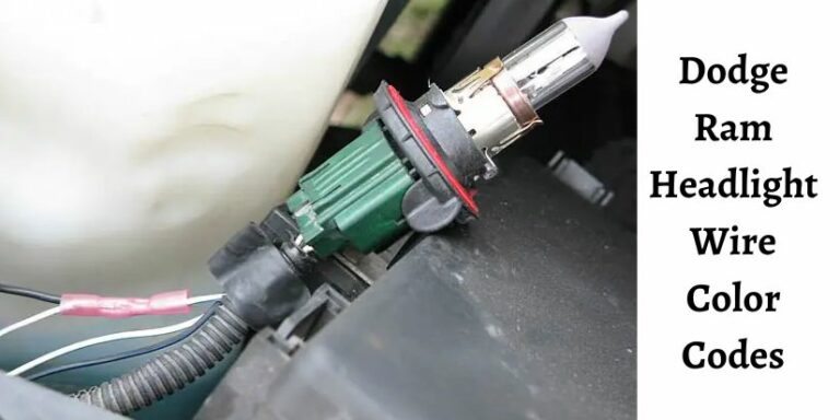
Dodge Ram Ignition Switch Wiring Harness Color Code Guide [2026]
Understanding the Dodge Ram ignition switch wiring harness is essential for troubleshooting starting issues or installing aftermarket electronics. The most critical connections include the Yellow starter wire and the Pink/White ignition wire, which vary slightly across different truck generations.
🎯 Key Takeaways
- Yellow is the standard color for the starter wire on most Ram models.
- Pink/White typically serves as the primary Ignition 1 power source.
- Constant 12V power is usually found on Red or Red/White wires.
- Accessory wires are often Orange and power non-essential cabin electronics.
- Always verify wires with a multimeter before making any permanent connections.
Identifying the correct wires in your Dodge Ram’s ignition harness is the difference between a successful installation and a blown fuse or damaged Body Control Module (BCM). Most modern Rams follow a specific color-coding logic where Pink/White typically handles the primary ignition circuit and Yellow triggers the starter motor. Knowing these specific pinouts is essential when you are installing a remote start, troubleshooting a no-start condition, or hardwiring accessories that need to turn on with the key.

You need to be precise because Dodge often changed wire colors between generations or even mid-year refreshes. Tapping into the wrong wire can lead to “ghost” draws on your battery or cause the vehicle to stall while driving. This guide focuses on the specific harness found behind the steering column, providing the exact color-to-function mapping you need for the most common Dodge Ram generations currently on the road.
Comprehensive Wire Color Charts for Dodge Ram Generations
When you pull the plastic shroud off your steering column, you will see a heavy-gauge wiring harness plugged into the ignition switch. This is the heart of your truck’s electrical system. While most of these wires look similar, their functions are vastly different. You must verify these colors with a digital multimeter before making any permanent splices.

2002–2008 Dodge Ram (3rd Generation)
The third-generation Ram is one of the most common trucks for aftermarket modifications. The ignition switch harness on these models is generally accessible and follows a fairly consistent color pattern across the 1500, 2500, and 3500 series. Note that the gauge (thickness) of these wires is significant because they carry high current.
- 12V Constant Power: Red or Red/Light Blue. This wire provides the “juice” to the switch at all times, regardless of key position.
- Starter: Yellow. This wire only shows 12V when you are physically holding the key in the “Start” position.
- Ignition 1 (Primary): Pink/White. This is the most critical wire. It provides power to the engine computer and fuel system. It stays energized during the cranking process.
- Accessory 1: Pink/Yellow. This powers your radio and windows. Crucially, this wire usually loses power while the engine is cranking to save battery amperage.
- Second Accessory: Dark Blue. Used in some models to power the climate control system (HVAC) while the engine is running.
- Key Sense: Tan/Light Blue. A thin wire that tells the truck the key is physically in the cylinder, often used for door chimes.
1994–2001 Dodge Ram (2nd Generation)
Second-gen Rams use a more traditional electrical setup. You will find that these wires are often even thicker than those in later models because they do not rely as heavily on relays to switch the load. If you are working on a 12-valve or 24-valve Cummins from this era, these are the wires you will interact with most.
- 12V Constant Power: Red and Red/White. Often, there are two separate feeds to provide enough current for the entire cab.
- Starter: Yellow. Triggers the starter solenoid.
- Ignition 1: Dark Blue. This powers the fuel shut-off solenoid on diesel models and the coil/injectors on gas models.
- Ignition 2: Black/Orange. Powers secondary systems that must remain on while the truck is running.
- Accessory: Black/White. Powers the heater fan and radio.
2009–2012 Dodge Ram (Early 4th Generation)
As the Ram moved into the fourth generation, the wiring became more complex with the introduction of the TIPM (Totally Integrated Power Module). However, the ignition switch still uses a physical harness that can be tapped into for most aftermarket needs.
- 12V Constant: Red/Gray or Red/White.
- Starter: Pink/White. Note: Do not confuse this with the Pink/White ignition wire on older models.
- Ignition: Pink/Light Green. This is the main “Run” circuit.
- Accessory: Purple/Brown. Usually controls the low-current trigger for the accessory relay.
The Ultimate Dodge Ram Ignition Switch Wiring Harness Walkthrough
Replacing or repairing the ignition switch wiring harness in a Dodge Ram is a common necessity for owners of second and third-generation trucks. Over time, high electrical resistance can lead to melted connectors, intermittent starting issues, or a total loss of power to the instrument cluster. This guide covers the meticulous process of accessing the steering column, identifying the specific color-coded wires, and ensuring a secure electrical connection to restore your vehicle’s reliability. Whether you are dealing with a “no-crank” situation or installing an aftermarket remote start, following these steps will ensure a professional-grade installation that prioritizes vehicle safety and circuit integrity.
Step 1: Disconnecting the Power and Safety Preparation
What you need: 10mm wrench, safety glasses, and a work light.
Instructions: Before touching any electrical component in your Dodge Ram, you must isolate the power. Use your 10mm wrench to loosen the nut on the negative battery terminal and pull the cable completely away from the post. Since you will be working directly on the steering column, this step is non-negotiable to prevent accidental airbag deployment or short-circuiting the harness. After disconnecting the battery, wait at least 15 minutes to allow the SRS (Supplemental Restraint System) capacitors to fully discharge. This “dwell time” ensures that even if you accidentally bump an airbag sensor or wire, the system remains inert. Place a rag over the battery terminal to ensure the cable doesn’t spring back and make contact while you are working.
Pro Tip: Turn on your headlights after disconnecting the battery; this helps drain any residual “ghost” voltage remaining in the capacitors and confirms the system is fully powered down.
Step 2: Removing the Steering Column Shrouds
What you need: Phillips head screwdriver, T20 Torx driver, and a plastic trim removal tool.
Instructions: The ignition switch harness is housed behind the plastic covers of the steering column. Begin by removing the screws located on the underside of the column. On most Dodge Ram models, there are two or three deep-set screws. If your truck has a tilt steering lever, you may need to unscrew it or pull it out depending on the specific year. Once the screws are out, use your plastic trim tool to gently pry the seam between the upper and lower halves of the shroud. Be careful not to snap the plastic clips that hold the two halves together. Set the plastic pieces aside in the backseat to prevent them from being stepped on or scratched during the repair process.
Pro Tip: Lower the steering wheel to its lowest tilt position before prying the shrouds apart; this provides more clearance and prevents the upper shroud from getting caught on the instrument cluster bezel.
Step 3: Accessing the Ignition Switch Assembly
What you need: T20 Security Torx bit (with the hole in the center) and a small flathead screwdriver.
Instructions: With the shrouds removed, you will see the ignition cylinder on the right and the electrical switch on the left side of the column. The switch is typically held in place by one or two security Torx screws. These screws have a small pin in the center, so a standard Torx bit will not fit. Carefully remove these screws and pull the switch housing away from the steering column. Do not force it; it should slide out once the fasteners are removed. You will now see the large wiring harness connector plugged into the back of the switch. This is the primary interface where most Dodge electrical failures occur due to heat buildup in the heavy-gauge wires.
Pro Tip: If the screw is stuck, do not strip the head. Apply a tiny drop of penetrating oil and ensure your bit is perfectly perpendicular to the screw head before applying pressure.
Step 4: Identifying Wire Functions and Mapping
What you need: Multimeter or test light, and a notepad.
Instructions: Dodge Rams use specific color coding, but these can vary slightly by year. Generally, you will find a thick Red or Pink/Black wire (Constant 12V Power), a Dark Blue wire (Ignition 1 Feed), and a Yellow wire (Starter Solenoid). It is vital to map these out before cutting or depinning. If you are replacing a melted harness with a pigtail, match the wire gauges carefully. The starter and constant power wires are usually 10 or 12-gauge, while the accessory wires are 14 or 16-gauge. Use your notepad to draw a quick diagram of the connector’s pinout. This ensures that even if the new pigtail has different colors, you know exactly which circuit connects to which pin on the switch.
Pro Tip: Always verify your “Hot” wire with a multimeter. Even with the battery connected (temporarily for testing), you should see 12.6V on the Red wire regardless of key position.
Step 5: Removing and Replacing the Harness Connector
What you need: Wire strippers, heavy-duty crimping tool, and heat-shrink butt connectors.
Instructions: If your harness is melted (a common Dodge “death” sign), you must cut the wires back to where the insulation is still flexible and clean. Cut one wire at a time to prevent confusion. Strip approximately 1/4 inch of insulation from the truck side and the new pigtail side. Insert the wires into a heat-shrink butt connector and crimp them firmly. Give each wire a “tug test” to ensure it won’t vibrate loose. Once crimped, use a heat gun to shrink the tubing until the internal adhesive seeps out slightly. This creates a waterproof, vibration-resistant seal that is far superior to standard electrical tape or cheap twist-on connectors. Repeat this for all 5 to 7 wires in the harness assembly.
Pro Tip: Stagger your cuts. By cutting each wire slightly shorter or longer than the one next to it, you prevent a massive “bulge” in the harness, making it much easier to tuck back into the steering column.
Step 6: Installing the New Switch and Routing
What you need: Zip ties and the T20 Security Torx driver.
Instructions: Plug the newly wired harness connector into the back of the ignition switch. You should hear a distinct “click” as the locking tab engages. Seat the switch back onto the steering column assembly, ensuring the clock-spring and ignition cylinder rod align perfectly with the switch’s internal gate. Reinstall the security Torx screws. Before putting the shrouds back on, use zip ties to secure the wiring harness to the steering column support. Ensure there is enough slack for the steering wheel to tilt up and down without tensioning the wires, but not so much slack that the wires interfere with the foot pedals or the shroud mounting points.
Pro Tip: Test the tilt mechanism through its full range of motion before tightening the zip ties to ensure no wires are being pinched or stretched.
Step 7: Final System Testing
What you need: 10mm wrench and your ignition key.
Instructions: Reconnect the negative battery terminal and tighten the 10mm nut. Sit in the driver’s seat and insert your key. Turn the key to the ‘Accessory’ (ACC) position and verify that the radio and power windows function. Next, turn it to ‘On’ (Run) and check that the dashboard lights up and the fuel pump primes. Finally, turn the key to ‘Start’. The engine should crank and fire immediately. If the truck starts but dies instantly, or if the dashboard remains dark, double-check your Ignition 1 (usually Dark Blue) and Ignition 2 (usually Pink/White) connections, as these control the PCM and cluster power. If everything works, cycle the key three times to ensure there are no intermittent connections.
Pro Tip: Watch for a “Security” or “Theft” light on the dash. Nếu it stays on, the Sentry Key Immobilizer module (SKIM) may not be communicating correctly with the harness.
Step 8: Reassembling the Steering Column
What you need: Phillips head screwdriver and original shroud screws.
Instructions: Once testing is successful, it is time to close up the column. Snap the upper and lower shrouds back together, ensuring the rubber gaskets around the ignition cylinder and the multi-function switch (turn signals) are properly seated. Reinstall the long screws from the bottom. Do not over-tighten them, as the plastic threads in the column can strip easily. If you removed the tilt lever, screw it back in now. Give the steering wheel one final wipe down to remove any grease or fingerprints from your hands during the installation. Your Dodge Ram ignition system is now refreshed and protected against the common melting issues that plague these trucks.
Pro Tip: If the shrouds don’t snap together easily, check to see if your new wiring bundle is blocking the plastic tabs. You may need to relocate a zip tie to get a flush fit.
✅ Final Checklist
- Battery terminal is tight and free of corrosion.
- All wires are crimped, heat-shrunk, and tug-tested for security.
- The steering wheel tilts freely without pulling on the new harness.
- The engine starts and all dashboard gauges/lights function normally.
- Column shrouds are aligned and screws are tightened without stripping.
Important Notes:
- Safety Warning: Never work on the ignition harness while the battery is connected; the airbag system is highly sensitive.
- Professional Help: Seek a professional if you see signs of significant melting on the main dash harness, as this may indicate a deeper short circuit.
- Estimated Time: 1 to 2 hours.
- Estimated Cost: $40 – $120 depending on if you replace just the pigtail or the entire ignition switch.
Understanding the Functional Roles of Ignition Harness Circuits
To successfully wire your truck, you have to understand more than just the color; you have to understand how the power behaves when you turn the key. Not every “hot” wire is the same. If you hook a remote start up to an Accessory wire instead of an Ignition wire, your truck might crank, but it will never actually start because the fuel pump isn’t getting power.
The Difference Between Ignition 1 and Accessory
The most common mistake you can make is confusing the Ignition 1 circuit with the Accessory circuit. When you turn your key to the “Start” position, the vehicle’s electrical system is designed to shed load. It wants every bit of battery power to go to the starter motor. To do this, the ignition switch internally disconnects the Accessory circuit (Pink/Yellow on most 3rd gens). If you tap your aftermarket device into this, it will lose power the moment you try to start the truck.
The Ignition 1 circuit (Pink/White), however, is “True Ignition.” It stays powered during the “Run” position and remains powered while the starter is turning. You must use this circuit for anything that the engine requires to function, such as an ignition bypass module or a secondary fuel pump controller.
Identifying the Starter Trigger
The Starter Wire (usually Yellow) is a momentary circuit. It should only ever show voltage when the key is turned to the final “Crank” position. If you see voltage on this wire while the truck is just sitting in “Run,” you have a short in the switch or a serious wiring fault. When using this wire for a kill switch or a remote start, ensure your connections are extremely secure. A loose connection on the starter wire is the leading cause of intermittent “click-no-start” issues in Dodge Rams.
The Role of Constant 12V Leads
The Red wires in your harness are your primary power sources. In many Dodge Rams, there are actually two of these wires. They are often protected by high-amperage fuses (40A or 50A) in the engine bay fuse box. If you are adding a high-draw accessory, you can tap into these, but it is always safer to use them only as a “trigger” to a relay that pulls power directly from the battery. This prevents you from overloading the factory ignition switch, which can melt if too much current is pulled through the internal contacts.
Comparison of Ignition Switch Wiring: 1500 vs. Heavy Duty Models
When diving into the ignition wire Dodge Ram ignition switch wiring harness, it is important to realize that not all Rams are built exactly the same. While the half-ton 1500 and the Heavy Duty (2500/3500) models share a lot of DNA, their electrical architectures often diverge based on the engine requirements and the intended use of the truck. If you are swapping parts or diagnosing a circuit, knowing these distinctions can save you hours of frustration.
Wire Gauge and Current Demands
In the Dodge Ram 1500, the wiring harness is generally designed for standard consumer use. However, the Heavy Duty models often feature thicker gauge wiring for specific ignition-fed circuits. This is particularly true for trucks equipped with the Cummins Turbo Diesel. Because diesel engines require high-current draws for components like grid heaters and heavy-duty starter solenoids, the primary ignition feeds (often the solid Red or Pink/White wires) might be beefier in a 2500 than in a 1500 of the same year. Using a 1500-spec harness in a 3500 can lead to overheating wires if the circuit isn’t rated for the HD current load.
Additional Accessory Circuits
Heavy Duty Rams frequently come from the factory with “upfitter” options or towing packages that the 1500 might lack. This means the ignition switch wiring harness on a 2500 or 3500 might have additional pinned locations or auxiliary wires intended to trigger relays for:
- Integrated trailer brake controllers
- Exterior clearance lighting
- High-idle switches (specific to diesel models)
- Transmission coolers with electric fans
Always verify the pin-out on your specific harness connector. A common mistake is assuming a 1500 harness will “plug and play” into an HD truck just because the plastic connector shell looks identical.
Common Failure Symptoms and Electrical Diagnostics for Ram Harnesses
The ignition system is the heart of your truck’s electrical operation. When the ignition wire Dodge Ram ignition switch wiring harness begins to fail, the symptoms can range from minor annoyances to leaving you stranded on the side of the road. Because these trucks vibrate significantly—especially the diesels—the harness is prone to physical wear and internal connection issues.
Intermittent Power Loss and the “Wiggle Test”
One of the most classic signs of a failing harness is intermittent electrical failure. You might notice your radio cuts out when you hit a bump, or the instrument cluster flickers momentarily. A practical diagnostic tip used by many Ram owners is the “wiggle test.” While the engine is idling, gently move the wiring harness leading into the back of the ignition switch. If the engine stumbles or the dash lights fluctuate, you’ve likely found a loose pin or a fractured wire inside the insulation. This is often caused by the heavy weight of large keychains pulling on the switch and harness over many years.
Identifying Heat Damage and Pitting
High electrical resistance creates heat. Over time, the metal pins inside the ignition switch wiring harness can become “pitted” or charred. This is a common failure point in the third and fourth-generation Rams. When you inspect the connector, look for:
- Discolored Plastic: Yellowing or browning around a specific pin hole (usually the high-draw constant 12V feed).
- Brittle Insulation: If the wire insulation near the connector feels crunchy or breaks when bent, it has been subjected to excessive heat.
- Voltage Drop: Using a multimeter, check the voltage at the battery and then at the ignition output wire. A loss of more than 0.5 volts indicates a poor connection within the harness or switch.
Ignoring these symptoms can eventually lead to a “no-crank” situation where the yellow starter wire never receives the signal to engage the solenoid, despite the battery being fully charged.
Conclusion
Understanding your ignition wire Dodge Ram ignition switch wiring harness is the best way to ensure your truck remains reliable and easy to troubleshoot. Whether you are dealing with the subtle differences between a 1500 and a Heavy Duty model or hunting down a mysterious power flicker, the color codes and circuit functions we have discussed are your roadmap. By paying close attention to wire gauges and watching for signs of heat damage, you can catch electrical issues before they turn into expensive repairs.
Your next step should be a physical inspection of your current harness to check for any signs of wear or brittle insulation. If you noticed any flickering or odd electrical behavior, grab a multimeter and verify those voltage levels at the switch. Stay proactive with your Ram’s electrical health, and your truck will keep cranking for years to come!
❓ Frequently Asked Questions
How do wire colors differ between a 3rd Gen and 4th Gen Dodge Ram?
3rd Gen Rams (2002-2008) use high-current wiring with thicker gauges, while 4th Gen Rams (2009-2018) transitioned to more complex CAN-bus integrated systems with thinner signal wires.
Why should I avoid using a test light on my Ram’s ignition harness?
Modern Dodge Rams use sensitive electronic control modules that can be damaged by the high current draw of a traditional bulb test light; a digital multimeter is required for safety.
What is the difference between the Ignition 1 and Ignition 2 wires?
Ignition 1 stays powered during engine cranking to run the fuel and spark systems, while Ignition 2 (often for HVAC) may drop power during cranking to assist the battery.
What does the Orange wire typically control in a Dodge Ram harness?
The Orange wire is usually the Accessory circuit, which provides power to the radio, wipers, and power windows when the key is in the ‘ACC’ or ‘ON’ position.
Can a damaged ignition wiring harness cause intermittent ‘No Start’ conditions?
Yes, heat and vibration can cause the pins in the plastic connector to loosen or corrode, leading to intermittent power loss to the starter or ignition circuits.
Which wire is used for a remote start tachometer signal in a Ram?
The tachometer signal is usually not found in the ignition switch harness; it is typically located at the fuel injectors or the coil packs under the hood.

![Best Air Bags for RAM 2500 Coil Springs: Full Specs & Data [2026]](https://truckguider.com/wp-content/uploads/2026/03/air-bags-for-ram-2500-with-coil-springs-featured.webp)