
Oil Pressu Sensor Cummins N14 Cummins N14 Oil Pressure 2026

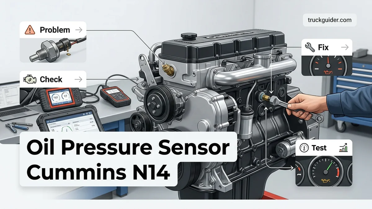
A failing Cummins N14 oil pressure sensor often triggers false dash warnings or ECM shutdown codes 143 and 415. The sensor sits on the engine’s left driver side along the main oil rifle passage, differing between Celect and Celect Plus platforms. Always verify actual oil pressure with a mechanical test gauge before replacing parts to rule out mechanical pump or bearing failure.
The Cummins N14 oil pressure sensor mounts on the driver side of the engine block, threaded directly into the main oil rifle. If your dash gauge suddenly drops to zero or your dashboard flashes a red stop engine lamp, a dead sensor or brittle wiring harness is the most common culprit rather than sudden internal bearing failure. Pinpointing the sensor immediately confirms whether your engine is in physical jeopardy or simply suffering from an electronic misread.

Prime for Young Adults — 6 Months Free
Students and 18–24s get six months of Prime free, then half price.
Start 6 Months FreeDifferentiating between true mechanical pressure loss and sensor failure prevents costly, unnecessary engine tear-downs. In 2026, original N14 wiring and legacy sending units continue to degrade from decades of heat cycles and vibration. Knowing exact sensor locations, matching the correct part numbers for Celect and Celect Plus systems, and bench-testing your circuit will keep your rig working without false alarms.
Key Takeaways
- Confirm oil pressure with a mechanical test gauge before replacing the electronic sensor.
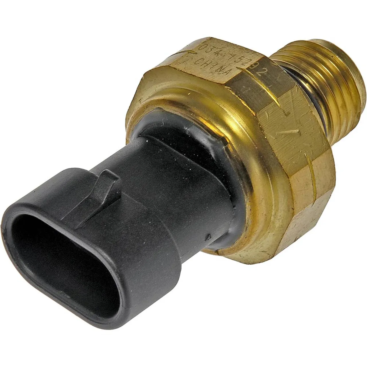
- Celect engines use a round 3-pin sensor; Celect Plus utilizes a triangular connector.
- Fault codes 143 and 415 signal warning and critical engine shutdown thresholds.
- Mount replacement sensors along the driver-side main oil rifle using minimal thread sealant.
- Torque the sensor to 10–12 lb-ft to prevent cracking the sensor body.
Diagnosing Cummins N14 Oil Pressure Sensor Failure vs. Mechanical Loss
Recommended Best Deal Products

When the electronic control module (ECM) detects an abnormal oil pressure reading, it logs specific fault codes that help narrow down whether the issue is electrical or hydraulic.
Fault Codes 143, 415, and 435 Explained
- Fault Code 143 (PID 100, FMI 1): Oil Pressure Low Warning. The ECM detects oil pressure dropping below the engine speed-dependent limit (usually below 10 PSI at idle).
- Fault Code 415 (PID 100, FMI 1): Oil Pressure Extremely Low. Critical threshold breached; the red stop engine lamp triggers, initiating automatic derate or engine shutdown protection.
- Fault Code 435 (PID 100, FMI 2): Oil Pressure Sensor Circuit Error. Signals an erratic or out-of-range voltage reading, directly pointing to sensor failure, broken pins, or fractured harness leads.
Mechanical Verification and Harness Testing
Never replace a sensor without verifying real-world oil pressure using a manual gauge. Thread a mechanical wet pressure gauge into an available 1/8-inch or 1/4-inch NPT oil gallery test port on the driver side rifle. At operating temperature (180°F to 200°F), an N14 must maintain a minimum of 10 PSI at 600 RPM idle and 35 to 45 PSI at 1800 RPM rated speed. If the mechanical gauge reads healthy pressure while the dash shows zero, the engine is physically sound.
Next, pull the sensor connector and inspect for internal oil wicking. Over time, engine oil pushes through the internal ceramic diaphragm, flooding the connector pins and shorting the 5-volt reference signal to ground. Test the three harness terminals with a multimeter: you should see a constant 5.0V excitation wire, a clean chassis ground return, and a fluctuating signal wire that produces between 0.5V (at 0 PSI) and 4.5V (at maximum pressure).
Master Cummins N14 Oil Pressure Sensor Replacement in 7 Simple Steps
The legendary Cummins N14 engine relies heavily on accurate oil pressure readings to protect its crankshaft, cam followers, and turbocharger from catastrophic failure. When the ECM detects erratic voltage or an out-of-range signal, it may illuminate the red stop-engine lamp or trigger derate modes even when mechanical pressure is fine. This practical walkthrough walks you through diagnosing, removing, and installing a new oil pressure sensor on your N14 engine to restore reliable monitoring and prevent false shutdowns.
Step 1: Read ECM Fault Codes and Verify Mechanical Pressure
What you need: Diagnostic scanner (Insite, Pro-Link, or generic heavy-duty OBD reader), mechanical oil pressure test gauge (0-100 PSI) with appropriate NPT/metric fittings.
Instructions: Connect your diagnostic tool to the 9-pin diagnostic port in the cab and read active/inactive fault codes. Common Cummins codes for this circuit include Code 135 (oil pressure sensor circuit high voltage) and Code 141 (circuit low voltage). Before replacing electronic parts, confirm you do not have genuine low engine oil pressure. Plumb a mechanical wet gauge directly into an adjacent main oil rifle gallery port on the engine block. Start the engine and verify your idle pressure is at least 10 PSI at 600 RPM and reaches 30 to 45 PSI at rated engine speed (1800-2100 RPM) at operating temperature.
Pro Tip: Never assume the sensor is faulty just because the dash gauge drops; running an N14 with actual oil starvation will quickly spin a rod bearing. Mechanical verification is essential insurance.
Step 2: Disconnect Power and Locate the Sensor
What you need: Battery disconnect switch or a 1/2-inch wrench for battery terminal studs, flashlight or work light, shop rags.

Audible — Listen Free for 30 Days
One free credit a month and thousands of titles included.
Listen Free for 30 DaysInstructions: Switch off the ignition and disconnect the negative battery cables to prevent accidental voltage spikes from reaching the Celect or Celect Plus ECM during servicing. Locate the oil pressure sensor on the driver (left) side of the engine block. On most N14 configurations, the sensor is threaded into the main oil rifle gallery near the ECM mounting plate, situated below the intake manifold and fuel cooling plate. Wipe away road grime and caked engine oil around the sensor body using a clean rag so debris cannot fall into the oil gallery when the sensor is loosened.
Pro Tip: On Celect Plus models, the oil pressure and ambient air/temperature sensors look remarkably similar; trace the harness lead to ensure you are wrenching on the unit tapped directly into the pressurized engine block gallery.
Step 3: Inspect and Disconnect the Wiring Harness
What you need: Electrical contact cleaner, pick tool or small flathead screwdriver, digital multimeter (DMM).
Instructions: Carefully slide the safety lock tab on the Weather Pack or Metri-Pack 3-pin connector. Depress the locking tang and gently wiggle the connector off the sensor body—never pull on the wires directly. Inspect the female terminal pins inside the plug for oil intrusion, green corrosion, or spread pins that cause poor pin tension. If oil has migrated through the old sensor into the harness connector, thoroughly flush the plug with electrical contact cleaner and blow it dry. Measure pin-to-pin voltage with the key on (after temporary battery reconnection): Pin A (ground), Pin B (5V reference from ECM), and Pin C (signal wire).
Pro Tip: Oil traveling through sensor pin seals into the harness pigtail (capillary action) is the leading cause of repeat sensor failures on N14 engines. If pins are oil-soaked, plan on splicing a new weather-sealed pigtail.
Step 4: Extract the Old Sensor
What you need: Deep-well oil pressure sensor socket (typically 1-1/16-inch or 27mm), 3/8-inch drive ratchet, extension bar, oil drain pan.
Instructions: Position your catch pan directly beneath the driver-side frame rail under the sensor location, as a small amount of residual engine oil will drain from the gallery port. Fit your sensor socket squarely over the hex base of the sensor. Turn counter-clockwise to break the initial torque. Because these sensors thread into iron blocks, they can gall or seize if dry; apply steady, square leverage to prevent shearing the brass threads. Once loosened, unscrew the sensor by hand and set it aside. Immediately plug the open block hole with a clean lint-free cloth.
Pro Tip: Avoid using standard open-end wrenches on thin sensor flats. The brass or lightweight aluminum bodies distort easily under angled pressure, which can strip the internal diaphragm or round off the hex.
Audible Premium Plus — Annual Membership
12 audiobook credits up front, plus the full Audible catalogue.
See Annual PlansStep 5: Prepare the Port and Install the New Sensor
What you need: OEM Cummins oil pressure sensor (e.g., part #4921487 or application-specific equivalent), lint-free cloth, Loctite PST 565 thread sealant (if sensor is not pre-coated).
Instructions: Clean the female pipe threads in the engine block gallery using a lint-free rag wrapped over a small brush to remove aged thread sealant and carbon deposits. Inspect the new sensor threads. Most genuine Cummins replacement sensors come with dry thread sealant pre-applied to the NPT threads. If bare, apply a light, even film of high-temperature liquid PTFE thread sealant across the second and third threads, leaving the leading thread clear. Thread the sensor into the block port by hand to avoid cross-threading. Tighten with your sensor socket to 10-12 lb-ft (14-16 Nm), or approximately 1.5 to 2 turns past hand-tight.
Pro Tip: Do not use traditional white Teflon tape. Stray shreds of shredded tape can shear off inside the gallery, bypass the oil filter, and plug tiny sensor ports or nearby cam follower oil feeds.
Step 6: Reconnect Harness and Secure Wire Routing
What you need: Dielectric grease (optional, light exterior application), heavy-duty zip ties, wire loom.
Instructions: Inspect the rubber seal inside the harness plug collar to ensure it is seated flush and undamaged. Push the harness plug straight onto the new sensor until an audible “click” is heard and the locking clip engages firmly. Push the secondary lock wedge into position. Check the wire harness path between the sensor and the main engine harness loom. The N14 produces noticeable vibration under load; ensure the wiring harness has a gentle drip loop and is zip-tied securely away from the exhaust manifold, hot turbo piping, and sharp edges of the ECM cooling plate.
Pro Tip: Leave approximately one inch of slack in the harness pigtail right at the sensor head. A harness tied down with zero slack will suffer stress cracks at the terminal crimps due to engine vibration.
Step 7: Clear Codes, Perform Calibration Check, and Test Run
What you need: Diagnostic scanner, shop safety glasses, torque wrench, clean rag.
Instructions: Reconnect the battery ground terminals and torque the nuts to spec (usually 10-15 lb-ft). Turn the ignition switch to the ON position without cranking the engine. Verify that the dash gauge sweeps and the red engine shutdown light does not illuminate. Connect your diagnostic scan tool, navigate to active fault codes, and confirm Code 135 or 141 has transitioned to inactive status; clear the inactive code history. Start the engine and let it idle. Observe real-time data on the scan tool and compare it to the dash gauge. Check around the sensor base for weeping oil leaks while the engine warms up.
Pro Tip: On key-on/engine-off, the ECM should read exactly 0 PSI. If your scanner displays a baseline of 5-15 PSI with the engine shut off, check for a poor ECM ground circuit.
✅ Final Checklist
- Mechanical oil pressure was verified with a manual gauge prior to final diagnosis.
- Sensor threads were torqued to specification (10-12 lb-ft) without using loose Teflon tape.
- Electrical connector is clean, dry, free of oil contamination, and positively latched with the lock pin.
- Harness has sufficient slack to absorb engine movement without contacting high-heat zones.
- Active fault codes are cleared from ECM memory and verified absent during hot engine idle.
- Zero oil seepage detected at the mounting threads during operational pressure testing.
Important Notes:
- Safety Warning: Allow the engine to cool down before servicing. The oil rifle gallery sits directly below the hot side of the engine, and oil can reach temperatures exceeding 220°F (104°C), presenting severe burn hazards.
- When to Seek Professional Help: If installing a verified new sensor and checking wire continuity does not clear low pressure codes, or if mechanical wet gauge readings reveal less than 10 PSI at hot idle, consult a heavy-duty diesel technician immediately to inspect the oil pump, pressure regulator valve, or main bearings.
- Estimated Time and Cost: Total labor time is approximately 45 to 90 minutes. A genuine Cummins replacement sensor typically costs between $65 and $140, whereas hiring a mobile heavy-duty diesel mechanic will range from $180 to $350 including labor and diagnostics.
Identifying Celect vs. Celect Plus Sensor Locations and Part Numbers
Cummins altered both the wiring protocol and sensor designs between early N14 Celect engines (built from 1990 to 1995) and late-model N14 Celect Plus engines (built from 1996 through the end of production). Installing the incorrect sender results in false codes or broken harness connectors.
N14 Celect (1990–1995) Placement and OEM Numbers
On early Celect engines, look on the lower left-hand side of the block, slightly behind the fuel pump and near the ECM cooling plate. The sensor threads directly into a tapped boss on the primary gallery rail.
- Visual Cue: Uses an older round 3-pin Weather-Pack style connector with a barrel-style latch.
- Thread Pitch: Typically features standard pipe threads (NPT) directly into the block adapter.
- Primary OEM Part Numbers: 3084521, 3080406, 3408345.
- Operating Signal: 5-volt analog voltage divider supplying a direct baseline to the early dual-connector ECM.
N14 Celect Plus (1996–2000+) Placement and OEM Numbers
The Celect Plus N14 features a redesigned engine wiring harness and a unified sensor housing. You will locate this sensor on the driver side, forward of the ECM, threaded into the oil rifle via a designated adapter port.
- Visual Cue: Uses a triangular or flattened Metri-Pack connector with an indexed locking tang to prevent reversed pin alignment.
- Thread Pitch: Utilizes straight metric threads (often M14 or 9/16-18) sealed with a viton O-ring rather than tapered pipe tape.
- Primary OEM Part Numbers: 4921517, 4076930, 3083716.
- Installation Note: Sensor 4921517 is the most prevalent replacement unit in active fleets today, known for improved internal seals that resist high oil wash pressures.
Step-by-Step Guide: How to Replace a Cummins N14 Oil Pressure Sensor
Replacing the oil pressure sensor on a Cummins N14 is a straightforward mechanical procedure. Complete this task when the engine is cold to avoid contact with hot fluids and manifold surfaces.
Removal and Installation Process
- Disconnect Battery Power: Disconnect the negative battery cables to prevent voltage spikes to the Electronic Control Module (ECM).
- Locate the Sensor: Find the sensor on the driver side of the engine block, situated near the ECM and fuel pump cooling plate.
- Clean the Area: Spray the sensor base with brake cleaner and wipe away road grime to prevent contaminants from entering the main oil rifle.
- Detach Wiring Harness: Depress the connector locking tab carefully. Slide the harness off the sensor terminals without pulling on the wires.
- Unthread Old Sensor: Use a 1-1/16-inch deep oil pressure switch socket to unthread the faulty sensor counter-clockwise.
- Install the Replacement: Hand-thread the replacement OEM sensor (such as Cummins part number 4921517 or 3080406) into the port.
- Torque to Specification: Tighten the sensor to 10 to 14 lb-ft (14 to 19 Nm) using a calibrated torque wrench. Do not overtighten, as overtightening cracks the brass threads.
- Reconnect Harness: Push the electrical plug back into the sensor until the locking mechanism clicks firmly into place.
Troubleshooting Persistent Low Pressure Codes and Wiring Harness Faults
If new hardware does not clear active fault codes, the underlying issue likely stems from harness deterioration or supply voltage anomalies. Common N14 diagnostic trouble codes include Code 135 (sensor voltage high) and Code 141 (sensor voltage low).
Testing the 5-Volt Reference Circuit
Modern service procedures in 2026 emphasize electrical testing before replacing components. Turn the ignition switch to the run position with the engine off. Measure the voltage across the sensor harness terminals using a digital multimeter. Terminal A must supply a steady 5.0 volts (±0.25V) directly from the ECM. Terminal B provides the sensor return ground. If the 5-volt reference drops below 4.75 volts, inspect the harness for abrasion against the engine block or corrosion at the ECM 28-pin connector.
Mechanical Verification with a Direct Gauge
Never rely solely on digital readings when troubleshooting active low-pressure codes like Code 143 or 415. Plumb a calibrated mechanical wet gauge directly into the main oil rifle port. Cummins factory specifications require a minimum of 10 psi (69 kPa) at idle (600 RPM) and 30 to 45 psi (207 to 310 kPa) at rated load speed (1800 to 2100 RPM) at standard operating temperature (180°F to 200°F).
What If It Still Doesn’t Work?
When both the sensor and harness circuits test normal but mechanical readings remain below factory tolerance, mechanical failure within the lubrication system is present. Execute the following contingency steps:
- Inspect the Pressure Regulator Valve: Check the oil pump pressure regulator plunger and spring for sticking, debris contamination, or spring fatigue.
- Check the Oil Suction Tube: Drop the oil pan and inspect the pickup tube gasket for cracks that permit pump aeration and cavitation.
- Perform Fluid Spectrometry: Order an oil analysis to identify elevated levels of copper, lead, or tin, which confirm main bearing journal wear.
- Test the ECM Driver Channel: Have an authorized service center test the ECM’s internal analog-to-digital converter if mechanical pressure is optimal but digital fault codes persist.
- Consult a Certified Heavy-Duty Shop: Seek professional service if internal component replacement is required. Professional diagnostic labor typically ranges between $200 and $450 in 2026, while complete oil pump or lower-end bearing overhauls average $2,200 to $5,000.
Conclusion
Cummins N14 oil pressure faults often stem from degrading sensors or wiring resistance rather than sudden mechanical failure. Systematically testing electrical supply lines, verifying torque values, and confirming manual oil pressure will prevent unnecessary overhauls. According to verified research and expert heavy-duty diesel sources, installing a direct mechanical test gauge is the mandatory first step before tearing down internal engine assemblies. Inspect your sensor wiring harness today to ensure reliable lubrication monitoring.
❓ Frequently Asked Questions
How do I test if my Cummins N14 oil pressure sensor is faulty?
Connect a manual mechanical pressure gauge directly into an open port on the engine oil rifle. Run the engine to operating temperature; if the mechanical gauge reads 10 psi or higher at idle while the ECM reads zero or triggers fault code 143, the sensor or harness is defective.
What is the normal oil pressure range for an N14 Cummins?
At full operating temperature, a healthy Cummins N14 should maintain 10 to 15 psi at hot idle (600–700 RPM) and 30 to 45 psi at rated cruise speed (1800–2100 RPM). Pressures dropping consistently below 10 psi at idle require immediate internal mechanical inspection.
What are the OEM part numbers for Cummins N14 oil pressure sensors?
Celect models typically require OEM part number 3083725 or 3080406 with the round 3-pin Metri-Pack connector. Celect Plus models require part number 4921517, 3408345, or 4076930 with the triangular 3-pin connector.
Should thread sealant or Teflon tape be used during sensor installation?
Apply a light coating of liquid PTFE thread sealant to the pipe threads, leaving the bottom two threads bare to prevent chemical contamination inside the oil rifle. Avoid thick Teflon tape, which can shred and clog the sensor orifice or internal oil pathways.
Why does my N14 oil pressure gauge drop instantly to zero while driving?
An instantaneous drop to zero almost always indicates an electrical failure, such as a severed 5-volt reference line, failed ground, or internal sensor open-circuit. True mechanical losses typically present with audible rod knock, turbo whine, or a gradual pressure drop before total failure.
How do I check the oil pressure sensor wiring harness for faults?
With the key on and engine off, disconnect the sensor harness and check for a steady 5-volt reference on pin A and ground continuity on pin B. Inspect the wire run around the ECM mounting bracket for chafing, heat damage, or oil saturation that could short the signal pin.
![6.7 Cummins Life Expectancy [2026]](https://truckguider.com/wp-content/uploads/2026/03/featured-17f2d286-768x768.webp)