Turbo Diesel 6.7 Cummins Engine Diagram: Technical Component Breakdown And System Schematics
For over fifteen years, the 6.7L Cummins Turbo Diesel has served as the backbone of the heavy-duty Ram truck lineup, renowned for its relentless torque and industrial-grade durability. Since its debut in mid-2007, this inline-six powerhouse has set the benchmark for towing capacity and longevity in the consumer pickup market. However, despite its reputation for reliability, the sheer complexity of the 6.7L’s modern common-rail fuel system and integrated emissions controls can make troubleshooting and maintenance a daunting task for owners and technicians alike. In this guide, we provide a professional-grade breakdown of the 6.7L Cummins engine diagram, detailing every critical component from the Holset VGT turbocharger to the SCR aftertreatment system to ensure you have the expert knowledge required for optimal engine care.
Anatomy of the 6.7 Cummins: Primary Component Identification
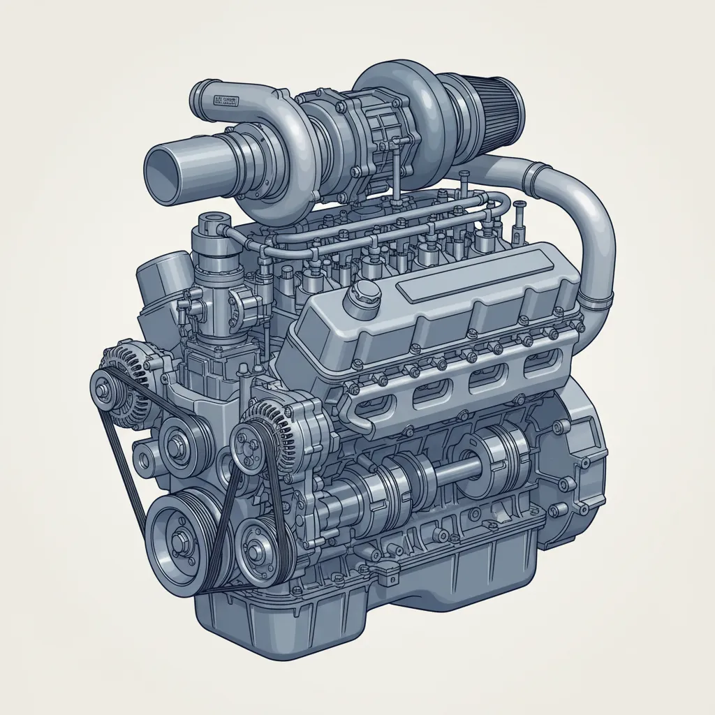
The 6.7L Cummins is an inline-6 cylinder diesel engine produced by Cummins Inc. for Ram trucks, and its physical architecture is a testament to heavy-duty engineering. At the core of the engine diagram is a deep-skirted cast iron engine block. This material choice is critical, as it provides the necessary rigidity to handle the immense cylinder pressures generated during high-torque operation. Unlike many V-8 competitors, the I-6 layout offers a simplified “hot side” and “cold side,” which simplifies the official guide to its external components.
Block Architecture and Cylinder Head
Research indicates that the 6.7L Cummins engine has a bore and stroke of 4.21 inches (107 mm) and 4.88 inches (124 mm) respectively. This undersquare design (long stroke) is the primary reason the engine produces such massive low-end torque. The cylinder head is a 24-valve, overhead valve (OHV) design using traditional pushrods. This cross-flow head design places the intake manifold on the driver’s side (cold side) and the exhaust manifold and turbocharger on the passenger side (hot side), optimizing thermal management.
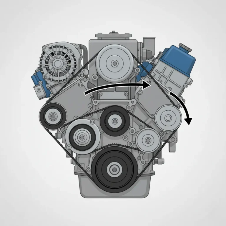
Front-End Accessory Drive (FEAD) and Cooling
The front of the engine features a robust serpentine belt system driving the water pump, alternator, and air conditioning compressor. A key expert insight for those viewing a 6.7 Cummins diagram is the location of the water pump—situated on the lower passenger side, it circulates coolant through internal water jackets to maintain a consistent operating temperature. In 2013+ models, the layout becomes more crowded due to the addition of various sensors and the SCR system components, distinguishing them from the earlier 2007.5–2012 non-DEF variants.
By The Numbers
Cubic Inch Displacement
Compression Ratio
Stroke Length
Holset VGT System: Forced Induction and Air Handling Schematics
The “Turbo” in Turbo Diesel is primarily represented by the Holset HE351VE Variable Geometry Turbocharger (VGT). Unlike a traditional fixed-vane turbo, the VGT uses an electronic actuator to move a sliding nozzle ring. This changes the exhaust gas velocity hitting the turbine wheel, effectively allowing the turbo to act like a small unit for quick spool-up at low RPMs and a large unit for high-end power.
Air Path and Charge Air Cooling
Following the air flow diagram, ambient air enters the air box, passes through the compressor side of the turbo, and is then routed to the Charge Air Cooler (CAC) or intercooler. This heat exchanger, located in front of the radiator, reduces the temperature of the compressed air to increase oxygen density. From there, the air enters the intake manifold. This system is critical for achieving the high output seen in modern variants, where torque reaches up to 1,075 lb-ft in High Output (HO) configurations.
Monitoring exhaust gas temperature (EGT) is highly recommended when towing heavy loads. Excessive EGTs can lead to “heat soak,” causing the VGT’s sliding nozzle to bind or the electronic actuator to fail prematurely due to thermal stress.
The Exhaust Brake Function
In addition to providing boost, the Holset VGT serves as an integrated exhaust brake. When activated, the actuator closes the nozzle ring, creating backpressure in the exhaust manifold that helps slow the vehicle down without using the service brakes. This is a vital feature for heavy-duty towing, but it also means that the turbo is a high-wear item. Carbon buildup on the vanes is a common failure point that can lead to a “stuck turbo” scenario, often triggered by prolonged idling or light-load driving.
Common Rail Direct Injection (CRDI) Fuel System Architecture
The 6.7L Cummins utilizes a Common Rail Direct Injection (CRDI) system to deliver fuel at extreme pressures. This system is what allows for the quiet, efficient, and powerful operation compared to older mechanical injection diesels. A typical fuel system schematic for this engine starts at the electric lift pump in the fuel tank, which sends fuel forward to the high-pressure injection pump.
Injection Pump Evolution: CP3 vs. CP4.2
A nuanced understanding of the 6.7 Cummins requires knowing the pump variations. Most models from 2007.5 to 2018 used the highly reliable Bosch CP3 pump. In 2019 and 2020, Ram transitioned to the Bosch CP4.2 pump, which eventually faced a major recall due to internal failure risks. By 2021, the system reverted to a modified CP3. Regardless of the pump model, the CRDI system operates at pressures ranging from 5,000 PSI at idle to over 29,000 PSI under full load.
Precision Injection
Piezo-electric injectors can perform multiple injection events per cycle for smoother combustion.
Fuel Cooling
A return line schematic cycles unused fuel back to the tank to dissipate heat and prevent cavitation.
The Role of the High-Pressure Rail
The injection pump feeds fuel into a thick-walled steel rail that acts as a localized reservoir. This rail dampens pressure pulses from the pump, ensuring that each injector has access to high-pressure fuel instantly. Given the precision tolerances, dual-stage fuel filtration is non-negotiable. Contaminants smaller than a human hair can ruin a set of injectors or the high-pressure pump, making fuel filter changes one of the most critical Ram specs to follow for longevity.
Aftertreatment and Emissions: DPF, SCR, and EGR Layout
To meet EPA Tier 4 Final standards, the 6.7L Cummins employs a complex sequence of emissions control components. Understanding the emissions schematic is essential for diagnosing the “limp mode” issues that often plague modern diesels. The system consists of three primary stages: Exhaust Gas Recirculation (EGR), the Diesel Particulate Filter (DPF), and Selective Catalytic Reduction (SCR).
DPF Regeneration and SCR Operation
The Diesel Particulate Filter (DPF) acts as a physical trap for soot. When the pressure differential sensors detect a restriction, the engine enters a “Regen” cycle, where extra fuel is injected during the exhaust stroke to raise exhaust temperatures and burn off the soot. In 2013+ models, the Selective Catalytic Reduction (SCR) system was added. This system injects Diesel Exhaust Fluid (DEF) into the exhaust stream. This allows the engine to be tuned for better fuel economy and power because the SCR handles the NOx reduction downstream, rather than relying solely on heavy EGR usage.
Using low-quality DEF or contaminated fuel can cause rapid crystallization in the SCR injector. Always source fresh DEF and ensure the tank cap is clean before refilling to avoid thousands of dollars in emissions repairs.
Reliability and Maintenance: A Professional Service Schedule
Applying engine diagram knowledge to practical maintenance is the key to reaching the legendary 300,000-mile-plus lifespan of the 6.7L Cummins. Maintenance on this platform is not just about changing fluids; it’s about protecting the high-cost components like the Holset VGT and the common rail injectors through the use of high-quality filters and expert tips for service intervals.
📋
Step-by-Step Maintenance Guide
Change the oil every 15,000 miles or 6 months. The 6.7L Cummins oil capacity is 12 quarts. Use 10W-30 or 5W-40 synthetic oil meeting CES 20081 or 20086 specifications.
Replace both the engine-mounted and chassis-mounted fuel filters simultaneously. This prevents the high-pressure pump from “starving” and protects the injectors from abrasive particles.
Replace the CCV filter (located on top of the valve cover) every 67,500 miles. A clogged CCV filter causes high crankcase pressure, which can blow out oil seals.
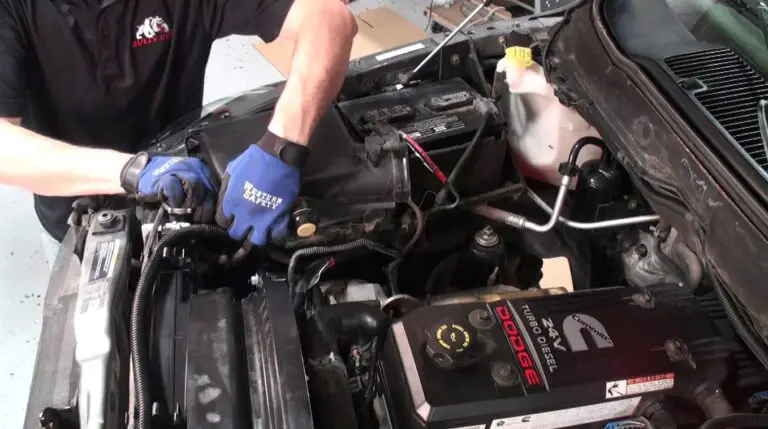
Visual Inspections and Troubleshooting
Using the engine diagram as your map, perform a visual sweep of the turbocharger oil feed lines and the serpentine belt tensioner once a month. Look for “sooting” around the EGR cooler and exhaust manifold, which indicates a leak. Additionally, for owners reaching the 100,000-mile milestone, it is wise to clean the MAP (Manifold Absolute Pressure) sensor, as it frequently becomes caked in oily soot from the EGR system, leading to incorrect boost readings and poor fuel economy.
✅ Why Owners Love It
- Unmatched low-end towing torque
- Simple I-6 layout for easier access
- Industrial-grade cast iron durability
- Excellent aftermarket support
❌ Potential Pitfalls
- High cost of emissions repairs
- VGT actuator sensitivity to heat
- Injector wear from poor fuel
- Weight limits front-end suspension
In summary, the 6.7L Cummins utilizes a sophisticated I-6 design that balances raw power with modern emissions compliance via DPF and SCR systems. The CRDI fuel system and VGT turbocharger are the primary drivers of the engine’s 1,000+ lb-ft torque potential, but they require diligent oversight. Consistent maintenance of high-pressure components and filtration systems is the key to achieving the legendary 300,000-mile-plus lifespan of this platform. Refer to your specific model year’s service manual for exact torque specs and use this diagram as a reliable foundation for your next diagnostic or performance upgrade project.
Frequently Asked Questions
What are the most common problems with the 6.7L Cummins?
The most frequent issues involve the emissions system, specifically EGR cooler clogging and DPF soot accumulation. Additionally, the Holset VGT actuator can fail due to heat and carbon buildup, and early 2019-2020 models experienced issues with the Bosch CP4.2 high-pressure fuel pump, which led many owners to seek CP3 conversions for improved reliability.
How often should I change the oil in my 6.7L Cummins?
Under normal operating conditions, Cummins and Ram recommend changing the oil every 15,000 miles or 6 months, whichever comes first. However, if you frequently tow heavy loads or idle for extended periods, it is professionally advised to shorten this interval to 7,500 miles to prevent oil dilution from DPF regeneration cycles.
What type of oil is best for the 6.7L Cummins?
A high-quality 10W-30 or 5W-40 heavy-duty engine oil that meets the CES 20081 or CES 20086 specification is required. It is vital to use ‘low-ash’ oil (API CJ-4 or CK-4) to prevent premature clogging of the Diesel Particulate Filter (DPF), which can be costly to replace.
How does the turbocharger work on the 6.7L Cummins?
The 6.7L uses a Holset Variable Geometry Turbocharger (VGT). Unlike traditional turbos, the VGT uses an internal sliding nozzle to vary the exhaust gas flow across the turbine blades. This allows the engine to simulate a smaller turbo for quick spooling at low RPMs and a larger turbo for maximum airflow at high RPMs, while also providing an exhaust braking function.
Why is my 6.7L Cummins consuming Diesel Exhaust Fluid (DEF)?
DEF consumption is a normal part of the Selective Catalytic Reduction (SCR) process used to reduce NOx emissions. Typically, DEF usage is proportional to fuel consumption; the more work the engine does (such as towing), the more DEF it will inject into the exhaust stream to neutralize pollutants. A typical ratio is roughly 2-3% of fuel consumption.