Where Is Tcm Located 99 Somoma Where Is TCM Located 99 2026

The 1999 GMC Sonoma does not use a standalone Transmission Control Module (TCM); transmission shifting is electronically managed by the central Powertrain Control Module (PCM/VCM). The module is mounted in the engine compartment on the passenger-side inner fender wall, directly below the coolant overflow and washer fluid reservoirs.
The Transmission Control Module (TCM) on your 1999 GMC Sonoma is physically located inside the engine compartment, mounted against the passenger-side inner fender wall. However, you will not find a separate, standalone box labeled “TCM.” On the 1999 Sonoma—across both the 2.2L inline-four and the 4.3L Vortec V6—General Motors integrated all electronic transmission controls directly into the primary Powertrain Control Module (PCM), commonly called the Vehicle Control Module (VCM).

Prime for Young Adults — 6 Months Free
Students and 18–24s get six months of Prime free, then half price.
Start 6 Months FreeKnowing this exact layout prevents you from wasting hours pulling down your interior dashboard or crawling under the chassis searching around the bellhousing. When your 4L60-E automatic transmission starts acting erratic, locking itself into limp mode, or throwing solenoid circuit codes, this single aluminum-cased computer under the hood is the precise component handling every shift command and line pressure calculation.
Key Takeaways
- A 1999 GMC Sonoma integrates transmission control into the primary Powertrain Control Module (PCM).
- The PCM is located on the passenger-side inner fender wall inside the engine bay.
- Unbolt the coolant overflow and washer fluid tank bracket to reach the computer.
- Always disconnect the negative battery cable before unplugging transmission module wiring harnesses.
- Check transmission fuses and shift solenoids before concluding the PCM has failed.
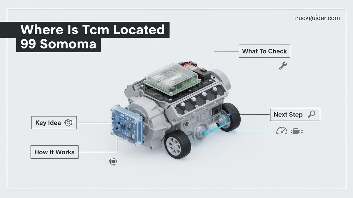
1999 GMC Sonoma TCM Location and PCM Integration Explained
Pinpointing the Module on the Passenger Inner Fender
To view the module, pop the hood and look along the passenger-side inner fender apron, positioned forward between the firewall and the front headlamp assembly. In factory configuration, the computer sits vertically inside a molded plastic bracket directly adjacent to—and partially beneath—the windshield washer solvent reservoir and coolant recovery tank.
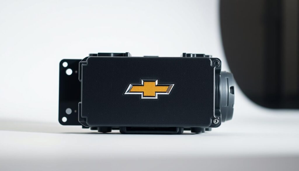
You can quickly confirm you have found the right module using these physical identifiers:
- Housing Style: A cast-aluminum rectangular case with external heat-dissipation fins along its spine.
- Connector Layout: Four distinct, high-density multi-pin wiring harnesses entering the module through keyed, color-coded retaining clips.
- Mounting Position: Slotted vertically into a plastic retaining frame secured with sheet-metal screws to the inner wheelhouse apron.
- Clearance: Tightly packaged against the inner fender liner, running parallel to the right-side exhaust manifold and heater core hoses.
Why There Is No Standalone TCM on a 1999 Sonoma
Drivers frequently search for a distinct TCM because newer trucks feature isolated transmission controllers (such as the GM T42 or T43 units). In 1999, GM utilized a centralized engine-and-transmission controller architecture. The VCM contains dedicated microprocessors and injector drivers on one side of its internal circuit board, while the reverse side houses the dedicated output drivers for the 4L60-E transmission’s electronic pressure control (EPC) solenoid, shift solenoids, and 3-2 downshift valves.
Because the transmission functions reside inside the primary engine computer, treating transmission control problems means troubleshooting the main engine management wiring. If an OBD-II diagnostic scanner cannot communicate with your transmission, you are dealing with a communication drop, a blown fuse, or a power loss at the primary VCM rather than a missing auxiliary box beneath the vehicle’s floorboards.
How to Locate and Inspect Your 1999 Sonoma TCM Like a Pro: A Practical Walkthrough
If you are experiencing erratic shifting, limp mode, or transmission error codes on your 1999 GMC Sonoma, finding the Transmission Control Module (TCM) is your first priority. Many owners struggle because General Motors did not install an independent, standalone TCM in this model year. Instead, transmission logic is integrated directly into the Powertrain Control Module (PCM/VCM), which governs both the engine and the 4L60-E automatic transmission. This practical walkthrough takes you step-by-step through safely locating, accessing, inspecting, and servicing this module under the hood without damaging sensitive electronics.
Step 1: Understand the Integrated Module Architecture
What you need: Vehicle owner’s manual, VIN tag confirmation, and a clean notepad.
Instructions: Before turning a single wrench, you must understand what you are hunting for. On a 1999 GMC Sonoma (whether equipped with the 2.2L inline-4 or the 4.3L Vortec V6), there is no isolated transmission computer hidden under the dash. General Motors combined the transmission and engine controls into a single cast-aluminum brain box called the PCM (often referred to in factory manuals as the VCM). This unit houses the shift solenoid drivers, pressure control solenoid circuits, and torque converter clutch logic inside an all-weather enclosure located in the engine compartment.
Pro Tip: Never waste money buying a standalone “TCM” from an aftermarket parts catalogue for a ’99 Sonoma; replacement units are sold strictly as complete engine/powertrain control modules.

Audible — Listen Free for 30 Days
One free credit a month and thousands of titles included.
Listen Free for 30 DaysStep 2: Park Safely and Disconnect Battery Power
What you need: Safety glasses, work gloves, and an 8mm or 5/16-inch box wrench.
Instructions: Park the Sonoma on a flat, dry surface, engage the parking brake firmly, and switch off the ignition. Pop the hood and locate the vehicle battery on the front driver side. To avoid sending high-voltage voltage spikes through delicate internal transistors or accidentally triggering short circuits during module removal, use your 8mm wrench to disconnect the negative (black) battery terminal cable. Tuck the disconnected cable safely away from the battery post to prevent accidental contact, and wait at least ten minutes for internal capacitors within the control system to fully discharge.
Pro Tip: Keep the positive terminal untouched; disconnecting only the negative side eliminates the risk of an accidental arc if your wrench touches grounded body metal.
Step 3: Locate the Module on the Passenger Inner Fender
What you need: High-output LED flashlight or work light.
Instructions: Walk over to the passenger side of the engine compartment. Look directly between the air filter housing assembly and the coolant recovery reservoir, mounted vertically against the inner fender well. The module sits upright in a black plastic retaining shroud or stamped steel bracket. You will recognize it by its ribbed aluminum casing (designed to dissipate heat) and four massive color-coded electrical wiring harnesses feeding straight into its top edge. This location exposes the module to engine bay heat, making proper physical inspection essential if you suspect heat-related shift failure.
Pro Tip: Wipe down excess road grime from the surrounding plastic shroud with a shop towel before touching any wiring to prevent dirt from falling into open pin terminals later.
Step 4: Remove Surrounding Intake Plumbing for Clear Access
What you need: Flathead screwdriver or 5/16-inch nut driver.
Instructions: While the module is visible, maneuvering hands and tools around it can be tight, particularly on 4.3L V6 models. Use your flathead screwdriver or 5/16-inch nut driver to loosen the hose clamp securing the flexible air intake duct to the air filter housing. Carefully pull the plastic snorkel duct away from the air box and swing it toward the engine center to give yourself wide-open clearance. If your vehicle has an auxiliary wiring loom clipped across the front of the bracket, gently detach the plastic push-clips using an automotive trim tool.
Audible Premium Plus — Annual Membership
12 audiobook credits up front, plus the full Audible catalogue.
See Annual PlansPro Tip: Cover the open air box inlet with a clean microfiber towel so loose screws, clips, or debris cannot fall into the engine intake tract.
Step 5: Release the Retaining Bracket Fasteners
What you need: 1/4-inch drive ratchet, 3-inch extension, and a 10mm socket.
Instructions: The module is held firmly inside a mounting bracket to shield it from harsh road vibration. Inspect the top and front edges of the bracket assembly. You will find two 10mm mounting bolts securing the upper retaining strap or clamshell cage to the inner fender apron. Fit your 10mm socket onto the extension and back these bolts out counterclockwise. Set the fasteners into a magnetic parts tray so they do not drop into the lower chassis frame. Once the bracket hardware is free, lift off the retaining cap or push back the flexible retention tab holding the module body upright.
Pro Tip: S-series trucks often suffer from rust around fender bolts; spray a light blast of penetrating oil onto the bolt threads from underneath if they resist turning.
Step 6: Disconnect the Four Wiring Harness Connectors
What you need: 7mm nut driver or socket, small flat-blade pocket screwdriver.
Instructions: The module interfaces with the transmission via four distinct 32-pin harness connectors (typically color-coded Blue, Red, White, and Clear/Black). Each harness connector is locked into place with a central 7mm retaining bolt or integrated squeeze-latch mechanism depending on your exact sub-model harness build. If your connectors feature central retaining bolts, back them out using your 7mm nut driver. The bolt remains captive within the plastic connector body. Gently rock the plug body back and forth while lifting upward. Do not pull on the wires themselves, as pulling wires can stretch or snap delicate copper terminal pins.
Pro Tip: Take a photo with your smartphone before disconnecting the plugs; although keyed, having a clear visual record of connector orientation guarantees foolproof reinstallation.
Step 7: Extract the Module and Inspect the Transmission Pins
What you need: Dedicated electronic contact cleaner, magnifying glass, and clean shop rags.
Instructions: Lift the module straight up out of the lower mounting cradle and bring it to a clean workbench. Use your flashlight and magnifying glass to inspect both the male pins inside the module headers and the female terminals inside the harness plugs. Pay special attention to the harness connectors handling transmission circuits (solenoids A and B, pressure control, and vehicle speed sensor pins). Check for bent pins, thermal discoloration, or green crusty corrosion caused by moisture intrusion from the wheel well. Spray the pins liberally with non-conductive electrical contact cleaner and allow them to evaporate completely.
Pro Tip: Never scrape pins with metal picks or screwdrivers; removing the micro-thin protective plating causes rapid terminal oxidation and recurring transmission communication errors.
Step 8: Reinstall and Re-initialize the Control System
What you need: 1/4-inch ratchet, 10mm socket, 7mm driver, and an OBD-II diagnostic scanner.
Instructions: Slide the module back down into its mounting cradle on the passenger fender. Reattach each wiring connector to its corresponding header, pressing down squarely until seated, then snug the 7mm retaining bolts to 32 inch-pounds (hand-tight—do not over-torque). Reinstall the bracket clamp and tighten the 10mm bolts. Reattach the air intake duct and secure its clamp. Finally, reconnect the negative battery cable and torque the terminal bolt to 11 ft-lbs. Start the engine, let it idle for two minutes, connect your OBD-II scanner, clear any stored transmission history codes, and perform a test drive to verify smooth gear shifts.
Pro Tip: After battery reconnection, the PCM must complete an idle and shift adapt relearn; drive moderately for the first 15 to 20 miles to allow internal line-pressure parameters to recalibrate.
✅ Final Checklist
- Confirmed the transmission control logic is housed inside the passenger-side PCM/VCM, not an independent box.
- Battery was completely disconnected prior to touching module pins to prevent circuit damage.
- All four harness connectors are fully seated with retaining bolts torqued evenly without stripping plastic.
- Air intake ducting and surrounding harness clips are reattached and air-tight.
- Diagnostic scanner shows communication with the transmission controller and no remaining active DTCs.
Important Notes:
- Static Electricity Warning: Electrostatic discharge can instantly ruin internal microchips. Ground yourself by touching bare vehicle sheet metal before handling the unshielded module pins.
- Security Programming: If you are installing a replacement PCM/VCM rather than inspecting your original, the truck will not start until a 30-minute Passlock security relearn or a professional scan tool flash is completed.
- When to Seek Professional Help: If physical pins look pristine but transmission shifting remains locked in second gear (limp mode) accompanied by no-communication codes (e.g., U1000 series), seek an automotive electrical specialist with GM Tech2 diagnostic equipment.
- Estimated Time and Cost: Accessing and inspecting the module takes approximately 30 to 45 minutes for a DIY mechanic. DIY inspection costs $10 to $15 for electrical contact cleaner. A remanufactured pre-programmed replacement module typically ranges from $150 to $300.
What Causes Transmission Control Failure Symptoms on a 99 Sonoma
Electrical Corrosion and Heat Exposure Under the Hood
Because GM positioned this combined controller inside the engine bay rather than the protected cabin, the unit endures extreme operating stress. The inner fender area absorbs continuous engine bay heat, road debris, and battery vapors. Over decades of service running through 2026, the weather-pack silicone seals inside the four wiring harness connectors dry out, crack, and admit moisture.
Common failure catalysts include:
- Oxidized Terminal Pins: Moisture seeping past the connector seals creates green oxidation on delicate copper pins, cutting signal voltage to the transmission’s 1-2 or 2-3 shift solenoids.
- Damaged Ground Circuits: The internal transmission drivers rely on direct chassis ground circuits grounded at the engine block and front fender. A loose or rusty ground creates immediate shifting errors.
- Cracked Solder Joints: Prolonged vibration from the passenger fender wall, paired with thousands of thermal expansion cycles, fractures the internal solder joints connecting the harness header to the printed circuit board.
Differentiating Computer Circuit Failure from Internal 4L60-E Mechanical Damage
You must determine whether erratic driving behavior originates from the VCM’s transmission circuits or mechanical gearbox failure before buying replacement electronics. When the VCM suffers an internal circuit interruption or loses system power, the 4L60-E automatically enters electronic fail-safe limp mode. The transmission defaults into third gear, line pressure maxes out to protect internal clutch packs, and reverse requires heavy throttle to engage.
If you experience abrupt, slamming 1-2 upshifts, scan the system for DTC codes P0751, P0753, or P0758. These point to electrical circuit faults inside the harness or the VCM itself. Conversely, if engine RPM flares wildly between gears or the fluid smells burnt, you are dealing with worn physical friction clutches, not an electronic control module failure.
How to Access and Remove the 1999 Sonoma PCM: Step-by-Step Fix
Because the 1999 GMC Sonoma integrates transmission control into the main powertrain control module (PCM), physical removal requires working on the passenger-side engine bay. General Motors positioned this module near the coolant reservoir and inner fender sheet metal.
Required Tools and Safety Preparation
Complete this job with standard hand tools. You will need an 8mm wrench for battery terminals, a 7mm socket for the harness retaining bolts, and a 10mm socket for bracket hardware.
Removal Procedure
- Disconnect Battery Power: Disconnect the negative battery terminal using an 8mm wrench. Wait at least 10 minutes to clear residual capacitive voltage from the module.
- Clear Surrounding Obstructions: Unbolt the coolant overflow reservoir bracket using a 10mm socket if equipped with the 4.3L V6 layout to gain full clearance.
- Unfasten Wiring Harness Connectors: Loosen the center retaining bolts on the two 80-pin harness connectors using a 7mm socket. Pull the connectors straight out to avoid bending internal pins.
- Extract the Module: Release the plastic retaining tabs on the PCM mounting bracket and slide the metal casing upward out of the engine compartment.
What If Shifting Problems Persist After Module Inspection
If inspecting or replacing the module does not resolve harsh shifting, slipping, or limp mode, the underlying defect likely resides inside the 4L60-E transmission or its secondary signal network.
Common Mechanical and Sensor Culprits
A failed Vehicle Speed Sensor (VSS) located on the transmission tail housing frequently mimics computer failure. Without accurate rotational speed data, the control unit cannot schedule upshifts. Furthermore, shift solenoids A and B inside the transmission pan commonly suffer electrical open circuits when operating temperatures exceed 200 degrees Fahrenheit.
Electrical Wiring and Grounding Faults
Wiring harness damage accounts for a significant portion of misdiagnosed shift faults. Inspect the round 13-pin transmission connector located on the passenger side of the transmission case for fluid contamination. Transmission fluid can wick into the harness pins, shorting the 12-volt power circuit to ground. Ensure engine ground strap G103 on the rear cylinder head remains clean and rust-free.
What If It Still Doesn’t Work?
When basic inspections fail to restore normal automatic shifting, follow these targeted escalation steps to isolate the issue without replacing functional components:
- Command Solenoids with Bidirectional Scanning: Connect an advanced diagnostic tool to command the 1-2 and 2-3 shift solenoids manually while monitoring live circuit state feedback.
- Perform a Resistance Test at the Case Connector: Unplug the main 13-pin transmission harness. Use a digital multimeter to measure resistance across pins A and B for Solenoid A (standard range is 20 to 30 ohms).
- Inspect Internal Valve Body Wear: Remove the transmission pan to evaluate fluid condition. Severe clutch debris indicates internal mechanical failure rather than a computing error.
- Consult an ASE-Certified Technician: If circuit resistance tests normal and the PCM receives proper voltage, schedule professional diagnostic service. In 2026, professional diagnostic fees range between $130 and $190, while a remanufactured, VIN-flashed control module costs between $300 and $550 including installation.
Conclusion
According to verified research and GM service technical documentation, the 1999 GMC Sonoma does not use a standalone TCM; transmission logic is executed entirely through the underhood PCM. If transmission DTCs arise, verify harness integrity and internal solenoid resistance before replacing the computer. Your immediate next step is to scan the vehicle with an OBD-II code reader to pull active transmission diagnostic trouble codes before unbolting any hardware.
❓ Frequently Asked Questions
Why can’t I find a separate TCM on my 1999 GMC Sonoma?
GM trucks of this generation, including the 1999 GMC Sonoma with the 4L60-E automatic transmission, combine both engine and transmission control into one unit known as the VCM or PCM. There is no independent external TCM box anywhere on the vehicle.
What symptoms indicate a failing PCM or transmission control circuit on a 99 Sonoma?
Symptoms include erratic gear changes, harsh shifts, getting stuck in second or third gear (limp mode), and speedometer failure. You will also typically see transmission-related trouble codes like P0751, P0756, or lost communication codes.
Do I need to program a replacement PCM for a 1999 GMC Sonoma?
Yes, a replacement PCM must be flashed with your specific Vehicle Identification Number (VIN) and engine/transmission calibration. It will also require a Passlock security relearn and a crankshaft position variation relearn to function correctly.
Could my transmission shifting issue be a blown fuse instead of a dead PCM?
Yes, a blown ‘TRANS’ fuse in the underhood fuse box will cut power to the shift solenoids, immediately causing the truck to enter third-gear limp mode. Always test these fuses with a multimeter before condemning the control module.
How do I safely disconnect the harness connectors from the module?
Disconnect the negative battery cable first to avoid shorting the computer. Then unclip the plastic connector retainers, loosen the 7mm center retaining bolts on each harness plug, and gently pull them straight out.
What internal transmission parts mimic a computer failure on a 99 Sonoma?
Failing shift solenoids (A and B), a worn 1-2 accumulator piston, or a damaged transmission wiring harness inside the pan can trigger the same shift errors as a malfunctioning computer.
![Ram 1500 Bed Replacement [2026]](https://truckguider.com/wp-content/uploads/2026/03/featured-714c2e0f.webp)

![PWQ Paint Code: Diagnosis & Repair [2026]](https://truckguider.com/wp-content/uploads/2026/03/pwq-paint-code-featured.webp)