2.7 Liter Toyota Tacoma Engine Diagram: 2026 Component Breakdown

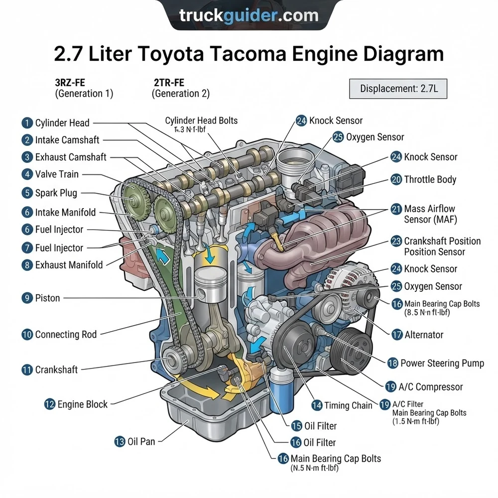
The 2.7 liter Toyota Tacoma engine diagram illustrates the inline-four 3RZ-FE and 2TR-FE DOHC architectures. Key schematics pinpoint the dual overhead camshaft configuration, 16-valve cylinder head, forged crankshaft, and connecting rod assemblies. Timing marks align on the crankshaft sprocket and intake/exhaust camshaft gears via dual marked chain links for accurate mechanical synchronization.
📌 Key Takeaways
- Cylinder head bolt torque requires a multi-step sequence finishing at 58 lb-ft plus 90-degree angle turn (2TR-FE).
- Generation identification relies on the transition from distributor/waste-spark 3RZ-FE to VVT-i equipped 2TR-FE in 2005.
- Connecting rod bearing journal oil clearance must measure between 0.0010 and 0.0022 inches.
- Plastic secondary air injection check valves and timing chain guide wear represent primary high-mileage failure points.
- Replace timing components and head gaskets via professional service if precision dial-indicator valve lash adjustments are required.
The 2.7-liter inline-four powerplant has served as the durable, high-torque baseline engine across three generations of the Toyota Tacoma. Beginning with the cast-iron 3RZ-FE and progressing to the 2TR-FE with intelligent variable valve timing, this engine family relies on a deep-skirt engine block, dual overhead camshafts, and an internal counter-rotating balance shaft assembly to eliminate secondary harmonic vibrations. Reading a 2.7 liter toyota tacoma engine diagram correctly requires a thorough understanding of its mechanical architecture, sensor locations, timing marks, fluid pathways, and bolt torque sequences. This technical guide delivers comprehensive schematics and procedural teardown specifications for professional mechanics and advanced technicians rebuilding, diagnosing, or servicing this platform.
High-Resolution Architectural Cutaway: Toyota 2.7L (2TR-FE/3RZ-FE) Engine Diagram displaying Cylinder Head Assembly, DOHC Valvetrain, Cylinder Block, Timing Chain Alignment Marks, and Fluid Circulation Routing.
2.7 Liter Toyota Tacoma Engine Diagram by Generation & Year




Diagnosing or rebuilding a 2.7-liter Tacoma requires distinguishing between the two primary engine designations: the 3RZ-FE (Generation 1) and the 2TR-FE (Generations 2 and 3). While both feature a 95.0 mm cylinder bore and a 95.0 mm stroke yielding an exact displacement of 2,693 cc (rounded up to 2,694 cc in late revisions), their top-end induction architecture, valvetrain actuation, timing drive, and engine management circuits differ substantially.
The Generation 1 3RZ-FE utilizes a cast-iron cylinder block with an aluminum cylinder head featuring shim-over-bucket valve lash adjustment and a distributor-based ignition system (updated in 1997 to a wasted-spark distributorless pack setup). In 2005, Toyota introduced the Generation 2 Tacoma equipped with the 2TR-FE. This revision altered the cylinder head casting to accommodate roller rocker arms with hydraulic lash adjusters (eliminating manual valve adjustment), an Electronic Throttle Control System-intelligent (ETCS-i), and Variable Valve Timing with intelligence (VVT-i) on the intake camshaft. In 2016, Generation 3 Tacomas received the updated 2TR-FE featuring Dual VVT-i, which independently alters both the intake and exhaust camshaft timing phases to reduce emissions and broaden the torque band.
| Generation & Year | Engine Code | Compression Ratio | Valvetrain / VVT Architecture | Fuel Pressure Spec |
|---|---|---|---|---|
| Tacoma Gen 1 (1995.5–2004) | 3RZ-FE | 9.5:1 | DOHC 16-Valve, Shim-Over-Bucket, Solid Lifters, Non-VVT-i | 38–44 PSI (Vacuum off: 265–304 kPa) |
| Tacoma Gen 2 (2005–2015) | 2TR-FE | 9.6:1 | DOHC 16-Valve, Roller Rockers, Hydraulic Lash, Single VVT-i (Intake) | 41–47 PSI (Constant: 284–325 kPa) |
| Tacoma Gen 3 (2016–2023) | 2TR-FE | 10.2:1 | DOHC 16-Valve, Roller Rockers, Hydraulic Lash, Dual VVT-i (Intake & Exhaust) | 41–49 PSI (Constant: 284–338 kPa) |
When swapping long blocks or sourcing replacement components, note that cylinder heads are not interchangeable across the 3RZ and 2TR generations. The revised oil galleys on the 2TR-FE engine block feed the oil control valves (OCV) that operate the camshaft phasers. Review our cross-reference guide for the larger 4.0L 1GR-FE Engine Diagram if you are comparing powertrain load ratings across model years.
2.7 Liter Toyota Tacoma Engine Diagram: Labeled Core Components



The 2.7-liter Tacoma power plant is an inline-four design arranged longitudinally in the engine bay. Understanding the spatial relationship of its subsystems on the technical diagram allows for accurate component location, sensor diagnostics, and teardown sequencing.
When referencing component orientations on Toyota technical diagrams, the front of the engine corresponds to the accessory drive pulleys (facing the radiator), while the rear corresponds to the flywheel/flexplate flange (mating to the bellhousing). Bank 1 refers to cylinders 1 through 4 sequentially from front to rear.
Cylinder Head and DOHC Valvetrain Architecture
The aluminum alloy cylinder head bolts directly to the cast-iron cylinder block via ten torque-to-yield head bolts. The valve train uses dual overhead camshafts driven by a single-stage primary roller chain. On the 2TR-FE, the intake camshaft incorporates a hydraulic VVT-i actuator sprocket that phases cam timing up to 45 crank degrees. The camshafts ride on precision-machined journals capped by split-aluminum bearing bridges, secured with 6 mm fasteners torqued to 12 ft-lbs (16 Nm). Two intake and two exhaust valves service each cylinder. In the 2TR-FE, these are actuated by needle-bearing roller rocker arms that pivot on stationary hydraulic lash adjusters (HLAs), eliminating regular valve clearance adjustments. Valve stem seals are viton-based, press-fit over the valve guides beneath the dual concentric valve springs.
Engine Block, Connecting Rods, and Crankshaft Assembly
The engine block is a high-strength cast-iron casting with a deep-skirt design extending below the crankshaft centerline, maximizing structural rigidity and dampening high-RPM vibrational harmonics. The forged steel crankshaft features five main journals and eight counterweights. It is secured to the crankcase by heavy cast bearing caps tied together through an integrated block ladder girdle. Symmetrically cracked, forged powder-metal connecting rods attach to the rod journals. These connecting rods house aluminum alloy pistons secured by floating wrist pins retained by dual internal snap rings. Hypereutectic aluminum pistons feature a graphite coating on the skirt surfaces to limit scuffing during cold starts, alongside an internal oil-cooling gallery fed by block-mounted piston oil squirt jets that spray pressurized lubricant directly against the underside of the piston domes.
Induction Manifold, Throttle Body, and Fuel Rail Layout
On the intake side (driver side of the engine bay on North American LHD trucks), the cast aluminum upper and composite lower intake manifold routes airflow from the air filter housing through an electronically actuated throttle body. The throttle assembly features an internal DC motor and a dual-wiper Hall-effect Throttle Position Sensor (TPS) outputting between 0.5V and 4.5V to the Engine Control Module (ECM). The fuel delivery rail mounts across the lower intake runner ports, retaining four multi-hole high-impedance (11.6–12.4 ohms) fuel injectors angled to spray directly onto the backs of the intake valve plates. Fuel is supplied by an in-tank turbine pump via a returnless line terminating in a quick-connect safety coupling at the rear of the fuel rail.
Exhaust Manifold and Catalyst Upstream Interface
Located on the passenger side of the engine assembly, the exhaust manifold is constructed from welded tubular stainless steel to resist thermal stress cracks. It merges the exhaust pulses of cylinders 1-4 and 2-3 into a 4-into-2-into-1 collector configuration before directing exhaust gases into the primary catalytic converter. The upstream Bank 1 Sensor 1 Air-Fuel Ratio (A/F) sensor threads directly into the manifold collector flange before the exhaust pipe flex joint, torqued to 32 ft-lbs (44 Nm).
Timing Chain Alignment Diagram for Camshaft and Crankshaft Gears


The 2.7-liter 2TR-FE and 3RZ-FE utilize an interference engine design. Should the camshafts and crankshaft lose synchronous mechanical timing, the intake and exhaust valve heads will impact the descending or ascending piston crowns, causing bent valve stems, punctured piston faces, and cracked guide sleeves. When working with the timing chain alignment diagram, you must strictly adhere to the designated colored links and alignment punch marks.
Never rotate the camshafts independently using a ratchet or breaker bar while the crankshaft remains stationary at Top Dead Center (TDC). The clearance between wide-open valves and the piston crowns is zero at TDC. Always verify the crankshaft is backed off roughly 30 to 45 degrees before servicing the valve train.
Setting Top Dead Center (TDC) on Cylinder #1
To align the timing assembly, rotate the crankshaft pulley clockwise using a 19 mm socket on the crank bolt until the timing notch on the serpentine harmonic balancer aligns with the “0” mark on the cast aluminum timing chain cover. Confirm that cylinder #1 is at Top Dead Center on its compression stroke by verifying that the camshaft lobe tips for cylinder #1 face upward and outward, away from each other. The alignment dot on the exhaust camshaft drive gear must point straight up toward the 12 o’clock position, and the corresponding notch on the intake VVT-i phaser housing must also align with the embossed indicator on the front camshaft bearing cap.
Timing Marks, Color Links, and Sprocket Meshing
The primary timing chain features three factory-marked colored links (typically two orange/yellow links and one dark blue/pink link). Install the chain following this precise gear alignment:
- Intake Camshaft Gear: Align the first yellow/orange chain link directly with the stamped punch dot on the outer perimeter of the intake VVT-i phaser gear assembly.
- Exhaust Camshaft Gear: Align the second yellow/orange chain link with the machined notch located on the exhaust camshaft timing gear. The link-to-tooth interface must mesh with zero chain slack across the top span between both camshafts.
- Crankshaft Sprocket: Align the single dark blue/pink chain link directly with the stamped circle or alignment dot found on the front tooth face of the lower crankshaft drive gear. At this position, the crankshaft drive gear Woodruff key must point directly toward the 12 o’clock vertical mark on the front oil pump case.
Primary Timing Chain Tensioner Retaining Bolts: 80 in-lbs (9.0 Nm)
Timing Chain Tensioner Slipper / Guide Rail Bolts: 15 ft-lbs (21 Nm)
Crankshaft Pulley Harmonic Balancer Bolt: 193 ft-lbs (262 Nm)
Camshaft Sprocket Flange Bolt (Exhaust): 58 ft-lbs (78 Nm)
VVT-i Gear Assembly Bolt (Intake): 63 ft-lbs (85 Nm)
Once the chain is placed over the gears, mount the fixed timing chain guide on the right side and the pivot slipper on the left side. Install the hydraulic timing chain tensioner by compressing the spring-loaded plunger into the body, engaging the pivoting safety hook, and torquing the two M6 bolts. After installation, pull the tensioner plunger back slightly or rotate the crankshaft clockwise 5 degrees to automatically release the safety latch, transferring mechanical spring force onto the chain slipper before the hydraulic oil pressure takes over.
2.7L Tacoma Serpentine Belt Diagram and Pulley Routing Paths



The front accessory drive system of the 2.7-liter engine utilizes a single heavy-duty 7-rib serpentine belt (7PK belt profile). The serpentine drive belt routes power from the lower crankshaft damper pulley to drive the engine water pump, the 80-amp to 130-amp alternator, the vane-type power steering hydraulic pump, and the air conditioning compressor. Routing differs significantly depending on whether the truck features factory air conditioning or an A/C bypass pulley.
| Pulley Component | Surface Type | Belt Interface Contact | Torque Spec / Bolt Size |
|---|---|---|---|
| Crankshaft Damper Pulley | Grooved (7 Rib) | Ribbed (Inside face of belt) | 193 ft-lbs (19 mm Center Bolt) |
| Automatic Belt Tensioner | Smooth (Steel) | Backside (Smooth back of belt) | 29 ft-lbs (Mounting Pivot Bolt) |
| Alternator Drive Pulley | Grooved (7 Rib) | Ribbed (Inside face of belt) | 81 ft-lbs (Shaft Nut) |
| Power Steering Pump Pulley | Grooved (7 Rib) | Ribbed (Inside face of belt) | 32 ft-lbs (Nut) |
| Water Pump Drive Pulley | Smooth (Steel) | Backside (Smooth back of belt) | 6.6 ft-lbs / 80 in-lbs (4x M6 Nuts) |
| A/C Compressor Clutch Pulley | Grooved (7 Rib) | Ribbed (Inside face of belt) | 18 ft-lbs (4x Mounting Bolts) |
Step-by-Step Routing with Factory Air Conditioning
When running a standard belt replacement on a 2.7L engine equipped with air conditioning, route the belt along the following sequence:
- Seat the ribbed face of the serpentine belt around the bottom groove of the lower Crankshaft Pulley.
- Loop the belt upward and route the smooth backside over the top of the Automatic Belt Tensioner Pulley.
- Route the belt rightward toward the driver side of the chassis, wrapping the ribbed side around the Power Steering Pump Pulley.
- Feed the belt downward and loop the ribbed side beneath the Alternator Pulley.
- Pull the belt up and route the smooth backside around the top of the center Water Pump Pulley.
- Direct the belt downward to the passenger side, looping the ribbed underside around the Air Conditioning Compressor Clutch Pulley.
- Relieve tension by attaching a long-handle 14 mm box wrench to the hex casting on the automatic tensioner arm. Rotate the tensioner counter-clockwise against spring pressure, slide the belt loop over the final pulley rim, and slowly release the wrench.
For trucks lacking factory A/C, the belt routes directly from the water pump down to the crankshaft pulley, utilizing an OEM-designated shorter serpentine belt (Toyota Part No. 90916-02556 or equivalent 7PK1895). Ensure the mechanical tensioner indicator mark settles between the minimum and maximum wear notches stamped into the cast tensioner bracket. For associated electrical connections, review our schematic covering the Tacoma Starter and Alternator Wiring Circuit.
Common 2.7 Tacoma Engine Diagram Failure Points and Oil Pan Leaks
The 2.7L platform has earned an exceptional reputation for durability, frequently logging in excess of 300,000 miles under proper fleet maintenance. However, several predictable mechanical failures develop on high-mileage engines. Technicians can use the following troubleshooting breakdown to isolate oil pan leaks, cooling anomalies, and emission valve faults directly on the engine diagram.
- Two-Piece Oil Pan Split Seam and Rear Main Flange: The 2TR-FE engine uses a two-piece oil pan design. The upper oil pan is a large aluminum casting that bridges the bottom of the cast-iron cylinder block and transmission bellhousing, acting as a structural brace. The lower oil pan is a stamped steel fluid sump. Both joints use no pre-formed paper gaskets; they rely entirely on Formed-In-Place Gasket (FIPG) sealant (ThreeBond 1207B or Permatex Ultra Grey). Chronic oil leaks routinely develop along the rear corners of the aluminum upper pan where it joins the rear crankshaft oil seal retainer. Remediating this leak requires lowering the front differential on 4WD models to clear the upper pan drop clearance.
- Water Pump Weep Port and Thermostat Bypass Tube: Coolant leaks typically manifest along the front timing cover face directly behind the water pump pulley. The internal ceramic mechanical water pump shaft seal deteriorates over thermal cycling, causing coolant to seep through the lower drain cavity (weep hole). Furthermore, the rear plastic bypass water pipe (connecting the thermostat housing to the rear heater core inlet) becomes brittle and fractures near the cylinder block union. When tracing loss of coolant, refer to our Tacoma Cooling System Diagnostic Guide to locate the lower manifold coolant runner O-rings.
- Secondary Air Injection Switching Valve Sticking (DTC P0418 / P2440): On 2012+ 2TR-FE engines, the Secondary Air Injection System introduces fresh air into the exhaust ports during cold starts to heat the catalytic converter quickly. The air switching valve mounted to the rear corner of the cylinder head is prone to internal condensation accumulation. Moisture corrodes the internal spring-loaded steel reed valves, causing them to freeze open or shut. This flags diagnostic trouble codes P0418 (relay fault) or P2440 (valve bank 1 stuck open), forcing the truck’s powertrain control module into safe-mode limp operation.
- Vacuum Line Hardening and PCV Valve Grommet Failure: The vacuum harness routes manifold vacuum across the throttle body, fuel pressure regulator (3RZ), EVAP purge solenoid, and positive crankcase ventilation (PCV) port. Over extended thermal cycles, the rubber PCV valve grommet located at the top rear of the stamped steel valve cover hardens into rigid plastic. This causes persistent unmetered oil vapor leaks and vacuum leaks that manifest as lean fuel codes (DTC P0171). The PCV valve itself (threaded metal valve on 2TR-FE: 20 ft-lbs / 27 Nm) can foul with sludged oil, sticking open and generating excessive crankcase blowby pressure.
- Oil Filter Adapter Housing O-Rings: On 2TR-FE variants with an integrated oil cooler, the aluminum adapter mounting bracket attaching the oil filter to the lower left side of the engine block contains two pre-formed viton D-rings. Over roughly 150,000 miles, these seals harden, flattening their sealing ridges. High oil pressure (up to 75 PSI cold) pushes oil out across the front differential casing and lower suspension control arm, mimicking a catastrophic lower engine block or oil pan leak.
2.7 Liter Toyota Tacoma Engine Diagram Technical FAQ
Is the 2.7L Toyota Tacoma 2TR-FE an interference or non-interference engine?
The 2.7L 2TR-FE (and its predecessor 3RZ-FE) is an interference engine. In the event of a timing chain fracture, severe chain guide failure, or incorrect timing chain link installation, the valves will make direct physical contact with the piston crowns. This causes bent valve stems, broken valve heads, damaged piston crowns, and destroyed cylinder head castings. Always rotate the engine over by hand through two complete 360-degree crankshaft revolutions after servicing the valvetrain to verify absolute mechanical clearance before using the starter motor.
What is the factory cylinder head bolt torque sequence and specification on the 2TR-FE?
Cylinder head bolt installation requires clean, lightly oiled threads and a multi-stage torque-to-yield sequence. Fasteners must be installed from the center outward in a criss-cross crisscross pattern across the ten bolt locations. For the 2TR-FE:
- Step 1: Torque all ten bolts in sequence to 29 ft-lbs (39 Nm).
- Step 2: Turn all ten bolts in sequence precisely 90 degrees clockwise.
- Step 3: Turn all ten bolts in sequence an additional 90 degrees clockwise (180 degrees total rotation).
Always inspect bolt length prior to reuse; if the bolt diameter is less than 10.5 mm at the narrowest waist, discard the bolt and install new OEM head bolts (Toyota Part No. 90910-02172).
What are the symptoms of a failed timing chain tensioner on a 2.7L Tacoma?
A failing hydraulic timing chain tensioner generates a pronounced metallic rattling or slapping noise from the front timing cover area, most prominent for the first 3 to 5 seconds during a cold engine startup before oil pressure builds. If the internal ratcheting teeth on the tensioner plunger strip or wear smooth, chain slack will allow the chain to slap against the cast aluminum timing cover, wearing deep grooves into the housing. In severe cases, the loose chain skips teeth on the camshaft drive gears, triggering check engine light codes P0016 (Crankshaft/Camshaft Position Correlation – Bank 1 Sensor A) and P0300 (Random Misfire).
Why does the 2.7L Tacoma oil pan use FIPG instead of a pre-cut rubber gasket?
Toyota engineers designed the mating interfaces between the engine block, aluminum upper oil pan, and stamped steel lower pan to tight tolerances that require high sheer-strength chemical sealants. Pre-cut cork or rubber gaskets compress unevenly over time, shifting under driveline torsional stress and engine vibration, ultimately resulting in chronic leaks. Formed-In-Place Gasket (specifically Toyota OEM Seal Packing 08826-00080 or ThreeBond 1207B) adheres at a molecular level to bare aluminum and cast iron, resisting thermal cycling, crankcase pressure, and continuous oil submersion up to 300°F (149°C).
What are the correct spark plug specifications and torque for the 2.7-liter engine?
The 2.7L 2TR-FE engine uses iridium-tipped spark plugs (Denso SK20HR11 or NGK ILFR6T11). The factory-mandated electrode gap is 0.043 inches (1.1 mm). Never adjust the gap with a traditional coin-style gapping tool, as this will shatter the fine-wire iridium tip. Thread the spark plugs into dry, clean cylinder head plug wells and torque them to 15 ft-lbs (20 Nm) using a rubber-insert 5/8-inch spark plug socket. Over-torquing can crack the thin aluminum casting threads of the cylinder head, while under-torquing allows combustion gas blow-by past the plug crush washer, leading to misfires under heavy throttle load.