2014 Ram 1500 Fuse Box 3.6 4WD Diagram: Troubleshooting 2026

The 2014 Ram 1500 3.6L 4WD fuse box (PDC/TIPM) is located in the engine compartment along the driver-side inner fender next to the battery. Fuse F10 (15A) powers the transfer case module, while Fuse F26 (25A) supplies the engine ECU. Unlatch the outer housing clips to access the micro-relays and cartridge fuses underneath.
📌 Key Takeaways
- Primary Power Distribution Center (PDC) houses critical 4WD transfer case fuse F10 (15A) and fuel pump fuse F70 (30A).
- Transfer case control module (TCCM) and front axle disconnect actuator rely on dedicated 12V ignition feeds from cavity F10 and F87.
- Mounting bracket bolts require a torque spec of 89 in-lbs (10 Nm) to avoid cracking the composite plastic housing.
- Common failure points include internal TIPM fuel pump relay degradation, terminal corrosion beneath block connector C1, and water intrusion.
- Replace blown mini-fuses yourself, but seek professional dealer-level reprogramming if the internal circuit board or integrated ECU power relay fails.
The 2014 Ram 1500 equipped with the 3.6L Pentastar V6 and four-wheel-drive (4WD) platform relies on a centralized electrical architecture managed through an underhood Power Distribution Center (PDC). Unlike earlier vehicle generations that separated circuit protection between an interior cabin panel and an underhood junction block, this fourth-generation Ram (DS body style) routes its primary power delivery, powertrain management, and drivetrain switching through a single, solid-state-enhanced fuse and relay block. Diagnosing electrical faults across the 3.6L V6 multi-point injection engine, the BorgWarner variable-torque transfer case, and associated solid-state modules requires an exact understanding of fuse assignments, busbar arrangements, and voltage drop diagnostic procedures across this central hub.

Prime for Young Adults — 6 Months Free
Students and 18–24s get six months of Prime free, then half price.
Start 6 Months Free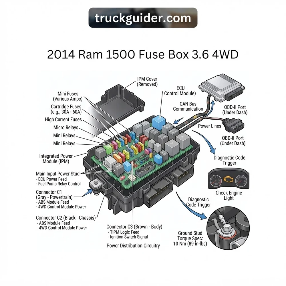
2014 Ram 1500 Fuse Box 3.6 4WD Location and Layout Architecture
Recommended Best Deal Products


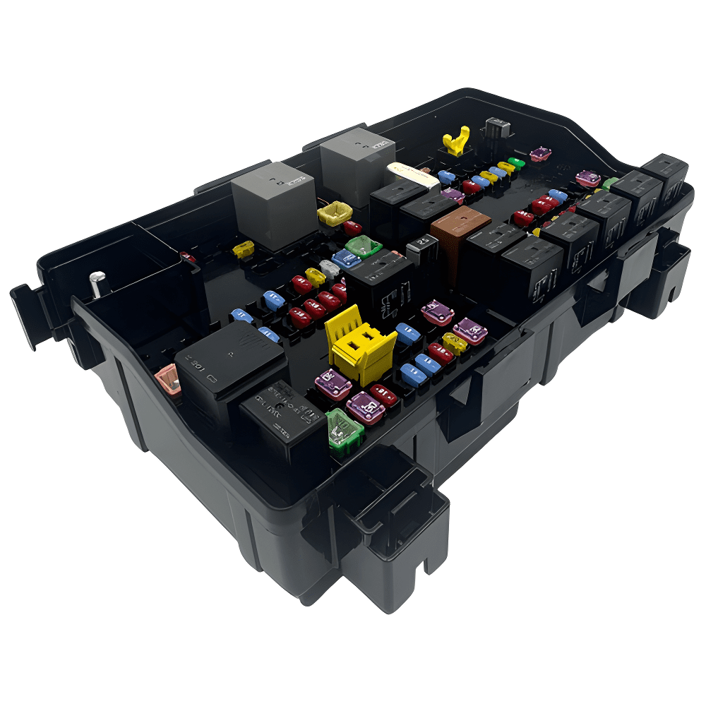
The Power Distribution Center (PDC) on the 2014 Ram 1500 is mounted directly in the engine compartment on the driver-side inner fender, immediately forward of the 12V lead-acid starting battery. Many technicians and owners search behind the knee bolster, beneath the steering column, or inside the glove compartment for a secondary interior fuse box. In the 2014 DS platform, no secondary interior fuse panel exists. Instead, the central underhood PDC feeds power to the cabin-mounted Body Control Module (BCM), which resides beneath the instrument panel on the driver-side kick panel. The BCM handles lower-amperage cabin lighting, door lock switching, and data gateway duties via internal microprocessors and solid-state drivers rather than serviceable traditional fuses.
The physical architecture of the 2014 Ram 1500 fuse box 3.6 4wd system features three distinct classes of circuit protection devices arrayed across a single injection-molded, weather-sealed tray:
- Micro Fuses (Micro2 and Mini Blade): Rated primarily between 5A and 30A, these safeguard low-to-medium current draws such as engine control sensors, ignition coils, the Transfer Case Control Module (TCCM) logic circuits, and cabin switch feeds.
- Cartridge Fuses (JCase and MCase): Rated between 20A and 60A, these protect high-inrush inductive and motor circuits, including the 4WD shift motor, radiator cooling fan, antilock braking system (ABS) pump, and blower motor.
- Plug-in Relays: The PDC incorporates both micro-relays and mini-ISO relays for switching high-amp line loads such as the starter solenoid, air conditioning clutch, powertrain main control, and electronic fuel pump. Certain models also feature solid-state relays embedded within the internal printed circuit board (PCB) layers of the assembly.
The top lid of the PDC contains an embossed schematic showing cavity designations (e.g., F01, F23, R11). Always cross-reference this plastic map with actual terminal positions, as mid-model-year running production changes by Chrysler can adjust individual cavity assignments between early-build and late-build 2014 trucks.
The underside of the PDC consists of several heavy-duty, multi-pin harness connectors locked into place with color-coded, mechanical lever-lock toggles. Power feeds into the PDC straight from the positive battery post through an insulated 2-gauge copper eyelet cable secured to the main B+ battery stud on the side of the housing. Below is the structural specifications table for the power distribution center housing and primary busbar elements:
| Structural Component | Type / Quantity | Functional Scope / Load Domain |
|---|---|---|
| Main B+ Stud | M8 x 1.25 Threaded Terminal | Direct 12V unswitched battery bus feed to primary PDC internal busbars |
| Cartridge Cavities | JCase / MCase (Slotted female) | High-load powertrain, EPS module, 4WD transfer case motor, ABS pump |
| Blade Cavities | Micro2 / Mini-blade (Dual blade) | Sensors, ECU logic, ignition coils, injectors, cabin control circuits |
| Relay Banks | 4-pin & 5-pin ISO Micro/Mini | Starter motor, ASD relay, fuel pump circuit, A/C compressor clutch |
| Harness Interface | 6 Cam-Lock Lever Connectors | Underhood chassis, cabin pass-through, transmission/transfer case harnesses |
3.6L Pentastar and 4WD Transfer Case Fuse Assignments
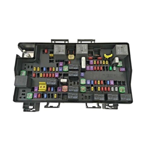
The 3.6L Pentastar V6 (variable valve timing, 24-valve) engine combined with the BorgWarner 44-44 (on-demand) or 44-45 (part-time) four-wheel-drive system requires specialized circuit protection tailored to high electrical loads. Unlike older hydraulic steering racks, the 2014 Ram 1500 utilizes an Electric Power Steering (EPS) system that demands immense current directly from the PDC busbar. Simultaneously, the 4WD Transfer Case Control Module (TCCM) cycles high amperage into an integrated encoder/actuator motor mounted directly to the transfer case output housing to engage the internal clutch pack or lock the collar.
The 3.6L engine also relies on targeted electrical pathways for its dual-stage variable-displacement oil pump, active intake manifold runner control, and pulse-width-modulated (PWM) coolant fan motor. Interruptions within these specific circuits alter engine coolant flow or cause erratic oil pressure readings at the instrument cluster. The table below details the critical fuses and relays dedicated to the 3.6L V6 powertrain and 4WD drivetrain systems in the 2014 Ram 1500:
| Cavity / ID | Rating (Amps) | Fuse Type | Protected Circuit / Target Component |
|---|---|---|---|
| F01 | 100A or 125A | Midi / Bolt-down | Electric Power Steering (EPS) Module Line Feed |
| F06 | 40A | JCase Cartridge | Engine Radiator Cooling Fan (PWM Controller feed) |
| F09 | 30A | JCase Cartridge | Transfer Case Control Module (TCCM) — High Current Motor |
| F20 | 30A | Mini Blade | Fuel Pump Relay Line Feed (Switched B+) |
| F23 | 20A | Mini Blade | Powertrain Control Module (PCM/ECU) Engine Logic Feed |
| F24 | 25A | Mini Blade | PCM / ECU — Ignition Coils and Camshaft Phasors (Timing Chain VVT) |
| F26 | 10A | Mini Blade | Transfer Case Control Module (TCCM) — Logic / Keyed Run-Start |
| F43 | 20A | Micro2 Blade | Fuel Injectors / Variable Displacement Oil Pressure Solenoid |
| F46 | 10A | Micro2 Blade | Active Grille Shutters, Purge Valve, Heated Thermostat |
| Relay 03 | Micro ISO | Plug-in Relay | Fuel Pump Relay (External bypass or standard socket) |
| Relay 06 | Mini ISO | Plug-in Relay | Starter Motor Solenoid Relay |
| Relay 11 | Mini ISO | Plug-in Relay | Auto Shutdown (ASD) Main Powertrain Relay |
When tracking intermittent 4WD lock issues, technicians must focus heavily on the relationship between F09 (high-draw shift actuator motor) and F26 (low-draw microprocessor wake-up signal). A blown F26 cuts all communications with the transfer case switch on the dashboard, leading to an immediate “4WD System Temporarily Unavailable” message on the Electronic Vehicle Information Center (EVIC). For deeper component locations, consult our detailed guide on the Transfer Case Control Module wiring architecture.
2014 Ram 1500 Fuse Box 3.6 4WD Failure Symptoms and Diagnostic Codes
Recommended Best Deal Products


A damaged or failing power distribution center on a 2014 Ram 1500 produces system-wide operational anomalies. Because the internal copper traces of the PDC carry multiplexed data feeds alongside high-current lines, moisture entry through cracked covers or failed locking tabs initiates localized electrolytic corrosion. When circuits lose stable voltage, multiple control modules set diagnostic trouble codes across the high-speed controller area network (CAN-C).
- Engine Cranks But Will Not Start (Fuel Delivery Breakdown): An open circuit on fuse F20 or internal failure of the fuel pump relay stops power transmission to the in-tank module. The engine cranks continuously with strong starter engagement, but fuel rail pressure remains at 0 PSI. Technicians often pull diagnostic code
P0627(Fuel Pump Control Circuit Open) orP025A(Fuel Pump Module Control Circuit). - Illuminated Check Engine Light with Oil Pressure Anomalies: The 3.6L Pentastar uses a dual-stage variable-displacement oil pump governed by a dual-stage solenoid valve wired through fuse F43. A blown F43 fuse or high pin resistance locks the pump into fail-safe high-pressure mode or leads to diagnostic code
P06DD(Dual Stage Engine Oil Pressure Control Circuit Stuck Low) orP0521(Engine Oil Pressure Sensor Performance). This warning often illuminates the check engine light alongside a chime on the instrument cluster. - “SERV 4WD” Warning and Inoperative Transfer Case Modes: Loss of continuous 12V voltage to the TCCM via fuse F09 or F26 drops the transfer case off the CAN-C network. The instrument panel clusters flash diagnostic code
U0102(Lost Communication with Transfer Case Control Module). The dashboard rotary dial or push-button selector will not illuminate, remaining unresponsive when switching between 2WD, 4WD Auto, and 4WD Lock. - VVT Phasor Faults and Camshaft Correlation Codes: The 3.6L utilizes double overhead camshafts where timing chain alignment is monitored by four variable valve timing phasers. If fuse F24 experiences severe voltage drops, the phaser oil control valves fail to respond quickly to PCM commands, leading to false sensor synchronizations and setting diagnostic codes
P0016(Crankshaft-Camshaft Correlation – Bank 1 Sensor A) orP0017, mimicking a stretched or broken timing chain. - Engine Overheating and Reduced Coolant Flow: Fuse F46 provides operating power to the active grille shutter actuators and the electronic thermostat heater. If this fuse blows, the shutters default to a closed aerodynamic profile, severely restricting engine bay airflow. In cold conditions, loss of the mapped thermostat heater restricts engine coolant flow past the primary radiator loop, triggering engine temperature spikes and diagnostic code
P0597(Thermostat Heater Control Circuit Open).
Do not continuously cycle the starter key when diagnostic code P06DD is present alongside a blown F43 fuse. Operating the 3.6L Pentastar under high loads without correct oil pressure regulation risks severe damage to camshaft journals, rocker arms, and the timing chain tensioners.

Audible — Listen Free for 30 Days
One free credit a month and thousands of titles included.
Listen Free for 30 DaysDiagnosing 2014 Ram 1500 Electrical Faults with OBD-II and Multimeter
Diagnosing an electrical malfunction originating inside or downstream of the 2014 Ram 1500 fuse box 3.6 4wd assembly demands a disciplined, low-impact testing routine. Never drive thick multimeter probe tips directly into female micro-fuse terminals; expanding these spring-loaded leaf contacts causes permanent fretting corrosion and terminal spread, which generates phantom intermittent open circuits. Follow this step-by-step procedure to isolate power distribution failures:
- Connect an Advanced OBD-II Diagnostic Scanner: Insert your scan tool into the 16-pin OBD-II data link connector located beneath the driver-side dashboard knee bolster. Turn the truck’s ignition switch to the “RUN” position without cranking the engine. Perform an all-module diagnostic trouble code sweep across the CAN-C and CAN-IHS networks. Note all module communication drops (DTCs beginning with “U”), as a clustered network failure often highlights a single blown fuse supplying a master control module.
- Verify Base Starting Battery Voltage at the PDC: Switch your digital multimeter (DMM) to DC Volts (20V scale). Place the negative black probe on the solid ground terminal of the 12V lead-acid starting battery. Place the red positive probe directly on the main B+ battery stud on the PDC housing. Manufacturer specs dictate that base resting voltage must read between 12.4V and 12.7V. If voltage reads below 12.2V, recharge the starting battery fully before continuing; low system input voltages generate false DTC entries across the ECU and TCCM.
- Perform Back-Probe Voltage Drop Testing on Target Fuses: Keep the ignition switch turned to “RUN.” Ground the black probe to the vehicle chassis. Using sharp, needle-point back-probe needles on your red lead, touch the two tiny exposed metallic test pads on the exposed top face of each Mini or Micro2 blade fuse. A healthy, fully operational circuit must show identical battery voltage on both test pads (e.g., 12.5V on Pin A, 12.5V on Pin B). A reading of 12.5V on one pad and 0V on the opposite pad indicates an open (blown) fuse element.
- Inspect Relay Sockets for Command Switching: If an operational system (such as the fuel pump or starter) fails while its corresponding fuse is intact, extract the relevant relay (e.g., Relay 03 or Relay 06). Inspect the underside plastic housing for melted terminals or heat discoloration. Set the DMM to resistance (ohms) to confirm the relay coil measures within OEM specifications (typically 60 to 120 ohms across terminals 85 and 86). Using a 12V fused test jumper, apply switch power across the coil pins and verify that continuity closes seamlessly with zero contact resistance across load terminals 30 and 87.
- Confirm CAN-C Network Line Health at Related Modules: When diagnosing transfer case or powertrain communication faults, monitor live data PIDs using the OBD-II tool. Review parameters such as “TCCM Desired Mode,” “Actual Transfer Case Position,” and “Dual-Stage Oil Pressure Switch Command.” If live data streams freeze or display out-of-range sensor voltage figures (e.g., 5.0V or 0.0V continuously), disconnect the PDC multi-pin harness connectors and check the underside pins for green copper sulfate buildup or water intrusion. Review our dedicated guide on Pentastar variable valve timing systems for correlated ECU pinout data.
Acceptable maximum voltage drop across any closed fuse element or operational relay terminal contact under load is 0.050 Volts (50 mV). Any reading exceeding 100 mV indicates excessive carbon pitting, terminal fretting, or internal PDC busbar oxidation.
2014 Ram 1500 Fuse Box 3.6 4WD Replacement and Service Precautions
Recommended Best Deal Products


Replacing the complete underhood Power Distribution Center on a 2014 Ram 1500 becomes necessary when water incurs inside the multi-layered internal busbars, causing unresolvable short circuits, parasitic draws, or burned fuse terminal cavities. Removing and servicing this assembly requires careful mechanical steps to avoid electrical arcs, damage to delicate harness terminals, and module desynchronization.
Before beginning mechanical disassembly, write down all active radio anti-theft codes and custom PCM configurations. Disconnect the negative 12V battery cable from the battery post, isolate it with an insulated cover, and wait a minimum of five full minutes. This delay is mandatory to let the Supplemental Restraint System (airbag control unit) backup capacitors bleed off their stored electrical charge, preventing accidental deployment while handling primary harness bundles under the hood.
Remove the plastic battery shroud and unthread the nut on the main B+ battery stud on the PDC using a standard 13mm socket. Pull the positive eyelet free. Carefully release the outer retaining tabs securing the PDC to the fender bracket and lift the box straight upward to access the bottom connectors. The underside features multi-pin harness connectors secured via rotating lever locks. Depress the safety locking tab on each lever and pivot the arm back completely; the mechanical lever automatically pushes the multi-pin connector out of its socket without placing stress on the underlying wires.
When reinstalling the PDC assembly, apply the following torque specifications according to OEM factory service manual instructions:
- Main PDC B+ Cable Stud Nut (M8 Thread): 15 Nm (133 in-lbs / 11 ft-lbs)
- PDC Support Bracket-to-Fender Bolts (M6 Thread): 9 Nm (80 in-lbs)
- Battery Terminal Clamp Fasteners: 5 Nm (44 in-lbs)
When installing a replacement PDC, inspect every female terminal on the vehicle harness connectors for backing out, bent locking tangs, or salt/moisture contamination. Treat weather seals with dielectric grease along the outer perimeter rubber seals only; do not pack terminal pin cavities directly with grease, as this creates hydraulic lock and attracts abrasive debris. Once all harnesses are seated, connect the main B+ battery cable and torque the nut to the specified value. Over-torquing will fracture the underlying plastic housing, creating an internal short circuit across the unswitched battery busbar.
After reconnecting the starting battery, cycle the ignition to the “RUN” position for 30 seconds before starting the engine. This initial pause allows the Body Control Module and Powertrain Control Module to execute bus synchronization, run transfer case encoder sweep calibrations, and re-establish communications across the entire CAN network. For deeper network details, reference our architecture overview covering Body Control Module network architecture.
Audible Premium Plus — Annual Membership
12 audiobook credits up front, plus the full Audible catalogue.
See Annual Plans2014 Ram 1500 Fuse Box 3.6 4WD Frequently Asked Questions
Where is the interior cabin fuse box located on a 2014 Ram 1500?
There is no interior cabin fuse box on a 2014 Ram 1500. All vehicle fuses, high-amp cartridges, and primary switching relays are consolidated inside the underhood Power Distribution Center (PDC) located beside the starting battery on the driver side. In-cab electrical circuits are monitored and driven electronically by the Body Control Module (BCM), located under the driver-side lower dash panel, using self-resetting solid-state drivers rather than replaceable fuses.
Which fuse controls the four-wheel-drive system on the 2014 Ram 1500 3.6L?
The 4WD system is protected primarily by two dedicated circuits in the underhood PDC: Fuse F09 (a 30-amp JCase cartridge fuse) provides main line power for the high-draw electric shift motor inside the transfer case actuator, while Fuse F26 (a 10-amp Mini-blade fuse) supplies ignition run/start signal voltage to the Transfer Case Control Module (TCCM) processor. If either fuse opens, the truck will not shift out of its current drive mode and will display a “SERV 4WD” warning.
Why does my 3.6L Pentastar engine run rough and display an oil pressure code after fuse inspection?
If fuse F43 was reinstalled into an incorrect empty cavity, or if the fuse blew during testing, the variable-displacement oil pump control solenoid loses operating power. This causes diagnostic code P06DD to set, forcing the oil pump into continuous maximum output and causing the ECU to restrict engine RPM via limp-in mode. Simultaneously, this circuit provides power to the variable valve timing phasors; losing it disrupts timing chain coordination and triggers erratic camshaft synchronization errors.
How do I identify a faulty integrated fuel pump relay in the 2014 Ram fuse box?
To verify if the fuel pump circuit failure is within the PDC, test for 12V switched battery power at fuse F20 while an assistant cranks the engine. If F20 shows direct battery voltage but zero current reaches the fuel pump wiring harness, the relay contacts are worn or damaged. In models with non-serviceable integrated PCB relays, technicians must install an external automotive bypass relay kit wired to switched run/start feeds, or replace the entire lower board of the PDC assembly.
Can an incorrect fuse rating trigger a check engine light on a 2014 Ram 1500?
Yes. Installing an improperly rated fuse or one with excessive internal resistance alters the precise voltage signals expected by the ECU. In circuits monitoring the active grille shutters, oxygen sensor heaters, or variable oil pressure solenoids, low voltage draws mimic short-circuit or open-circuit failure modes. The ECU detects this imbalance, logs a diagnostic code, and immediately illuminates the check engine light on the instrument cluster.
Step-by-Step Guide to Understanding the 2014 Ram1500 Fuse Box 3.6 4Wd
Identify – Verify vehicle ignition is OFF, disconnect negative battery terminal, and review the PDC diagram underside.
Locate – Find the primary fuse box on the driver-side fender bay directly adjacent to the 12V battery.
Reference – Cross-reference the suspect 4WD or ECU circuit number using the diagram matrix to locate its exact fuse cavity.
Connect/Route – Remove blown fuses using a fuse puller and install matching-amperage replacements, ensuring pin spades seat firmly without bending.
Verify – Reconnect the battery, scan the system with an OBD-II tool to confirm the diagnostic code is cleared, and observe that the check engine light extinguishes.
Troubleshoot – If the new fuse immediately blows upon key-on, trace wiring harness for short-to-ground faults along the transfer case actuator harness.