2001 Ford F150 4.2 Firing Order Diagram: 2026 Repair

The 2001 Ford F-150 4.2L V6 firing order is 1-4-2-5-3-6. Cylinders 1-2-3 are positioned front-to-back on the passenger side; cylinders 4-5-6 run front-to-back on the driver side. The coil pack towers route correspondingly: passenger side ports feed cylinders 1, 2, 3, while driver side ports power cylinders 5, 6, 4.
📌 Key Takeaways
- Engine firing sequence follows 1-4-2-5-3-6 with standard coil pack ignition
- Bank 1 (cylinders 1-3) is passenger side; Bank 2 (cylinders 4-6) is driver side
- Spark plug gap specification is strictly 0.052 to 0.056 inches (1.32-1.42 mm)
- Cross-routing wires on coil pack towers 4 and 5 is the leading cause of P0300 codes
- Replace damaged wire retainers immediately; seek a shop if ignition harness wiring faults persist
The 2001 Ford F-150 equipped with the 4.2-liter Essex V6 relies on an electronic distributorless ignition system (EDIS) governed by the Powertrain Control Module (PCM). Unlike conventional distributor systems that route high-tension voltage through a central mechanical rotor, the 4.2L engine uses a waste-spark multi-coil configuration. Pinpointing the correct cylinder configuration, tower positions, and routing layout is critical for preventing driveability issues such as secondary ignition crossfire, companion cylinder misfires, and catalytic converter damage. This technical guide delivers the complete schematic layout, firing order sequence, component specifications, and step-by-step assembly diagnostics required to service the 2001 Ford F-150 4.2L ignition system to OEM standards.
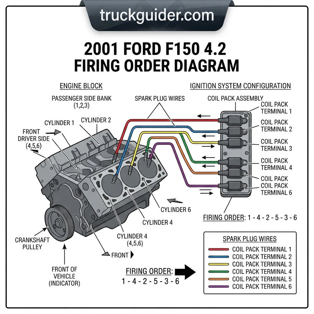
2001 Ford F150 4.2 Firing Order Diagram and Engine Layout




The 2001 Ford F-150 4.2L (256 cubic inch) engine belongs to the Ford Essex V6 engine family. It features a 90-degree cylinder bank angle with cast-iron block construction, pushrod valve actuation, and aluminum cylinder heads. Understanding the physical layout of the engine bay is essential before connecting any secondary ignition cables. Ford designates cylinder numbering based on physical position rather than firing sequence: Bank 1 sits on the passenger side (front to rear: Cylinders 1, 2, 3), while Bank 2 sits on the driver side (front to rear: Cylinders 4, 5, 6).
The firing order for the 4.2L Essex engine is 1-4-2-5-3-6. Because this engine employs a waste-spark ignition strategy, the single ignition coil pack houses three individual primary ignition coils. Each primary coil controls two secondary towers simultaneously. When a primary circuit collapses, both spark plugs on that coil fire at the exact same instant: one cylinder fires on its compression stroke to produce power, while its companion cylinder fires on its exhaust stroke (the “wasted” spark) to complete the secondary circuit return path.
Companion cylinders share a single coil circuit and fire 360 crankshaft degrees apart. On the 2001 4.2L V6, the paired companion cylinders are 1 and 5, 2 and 6, and 3 and 4. If an internal coil driver fails inside the coil pack or PCM, both cylinders in the pair will record simultaneous misfires.
The ignition coil pack is mounted atop the engine, positioned on the rear passenger-side intake manifold plenum. Misidentifying the coil pack towers is the single most common cause of no-start or severe misfire conditions after servicing spark plug wires. The stamped numbers on aftermarket coil packs often disagree with factory Motorcraft units; therefore, relying strictly on physical tower position is mandatory.
| Engine Attribute | OEM Specification / Layout | Diagnostic / Technical Detail |
|---|---|---|
| Firing Order | 1 – 4 – 2 – 5 – 3 – 6 | Clockwise rotation from front timing cover |
| Cylinder Bank 1 | Passenger Side (Right) | Cylinders 1 (front), 2 (middle), 3 (firewall) |
| Cylinder Bank 2 | Driver Side (Left) | Cylinders 4 (front), 5 (middle), 6 (firewall) |
| Coil Pack Companion Towers | Coil 1: 1 & 5 | Coil 2: 2 & 6 | Coil 3: 3 & 4 | Three internal dual-output ignition coils |
| Physical Coil Tower Mapping | Front Row: 4 – 6 – 5 | Rear Row: 1 – 2 – 3 | Front = Radiator side; Rear = Firewall side |
| Spark Plug Gap | 0.052 to 0.056 inches (1.32 to 1.42 mm) | Factory spec for Motorcraft AGSF-34EE plugs |
| Spark Plug Torque | 11 to 14 lb-ft (15 to 19 Nm) | Install dry into aluminum cylinder head threads |
When standing at the front bumper looking directly into the engine bay, the coil pack towers are oriented in two rows of three. The rear row (closest to the firewall) corresponds sequentially from left to right as Cylinder 1, Cylinder 2, and Cylinder 3. The front row (closest to the radiator) does not run sequentially; from left to right, it corresponds to Cylinder 4, Cylinder 6, and Cylinder 5. This counter-intuitive arrangement is why mechanics frequently cross the leads for cylinders 5 and 6 during routine wire replacements. While similar modular V8 engines from this era use individual coil-on-plug boots (as detailed in our Ford 4.6L Triton firing order guide), the 4.2L Essex relies entirely on this clustered waste-spark tower design.
Ignition System Components in the 4.2L F-150 Blueprint


The secondary ignition structure of the 2001 F-150 4.2L system is an interconnected electro-mechanical loop. Each component plays a distinct role in transforming low-voltage DC current into high-energy capacitive discharge arcs. Below is the technical breakdown of every major hardware component within this ignition circuit.
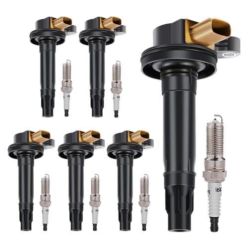
Ignition Coil Pack (Motorcraft DG-530 / 1F2Z-12029-AC)
The coil pack contains three independent primary windings and three secondary windings sealed in an epoxy-filled housing. The assembly receives switched 12-volt battery power via a single Red/Light Green wire at pin 4 of the electrical harness connector. Pins 1, 2, and 3 are individual ground-trigger lines pulsed by the PCM’s internal solid-state drivers (Coil A, Coil B, and Coil C). When the PCM interrupts the primary ground path, magnetic field collapse induces a high-voltage spike of 25,000 to 38,000 volts across the secondary windings. Because both ends of the secondary winding terminate at external spark plug towers, current exits one tower, jumps the plug gap to cylinder head ground, travels across the engine block casting, enters the companion plug gap in reverse polarity, and returns to the other end of the secondary winding.
Coil Pack Primary Resistance (Pins 1, 2, or 3 to B+ Pin 4): 0.4 to 0.8 ohms at 70°F (21°C). Secondary Resistance (measured between companion tower pairs 1-5, 2-6, and 3-4): 10,500 to 14,500 ohms. Any tower pair showing infinite resistance (open circuit) requires immediate assembly replacement.
High-Tension Spark Plug Wires
The 4.2L Essex uses 8mm silicone-insulated high-tension leads equipped with Kevlar-reinforced fiberglass cores impregnated with carbon. These suppressor cables attenuate electromagnetic interference (EMI) that can disrupt the PCM’s digital logic and digital sensor lines. Maximum acceptable cable resistance is 7,000 ohms per linear foot, with a total service ceiling of 30,000 ohms for the longest passenger-side run (Cylinder 3). The boots feature molded locking tabs designed to seat inside the recessed spark plug wells of the aluminum heads, locking out engine bay oil, road grime, and moisture.
Motorcraft Spark Plugs (AGSF-34EE / SP-504)
Because the waste-spark strategy forces companion plugs to fire in alternating polarity (one plug fires center-to-side electrode, the companion fires side-to-center electrode), double-platinum or fine-wire iridium plugs are strictly required by the OEM blueprint. Standard single-platinum plugs will rapidly erode the ground electrode on cylinders 4, 5, and 6 due to reverse-polarity electro-stripping. Plugs must be gapped between 0.052 and 0.056 inches using a wire gauge rather than a wedge tool to avoid cracking the platinum pads.
Camshaft Position (CMP) Synchronizer and Sensor
Mounted in the forward engine valley where a traditional distributor once sat, the CMP synchronizer is driven by a helical gear off the engine camshaft. It consists of a cast aluminum housing, an internal rotating shutter wheel with a single cutout vane, and a top-mounted Hall-effect sensor. As the camshaft turns, the shutter wheel passes through the sensor’s magnetic field, generating a digital 12V high / 0V low square-wave signal sent directly to PCM Pin 85. The PCM processes this signal alongside the Crankshaft Position (CKP) sensor input to differentiate between Cylinder 1 compression stroke and Cylinder 1 exhaust stroke, ensuring proper sequential fuel injection timing and coil primary dwell phasing.
How to Wire the 2001 Ford F150 4.2 Coil Pack Step by Step
Replacing or rewiring the spark plug leads on the 2001 Ford F-150 4.2L requires methodical routing. Due to the high secondary voltage and closely bundled harness paths, sloppy wire management will induce electromagnetic crossfire—a condition where the high-voltage pulse in one wire induces a false spark in an adjacent wire, causing detonation under load.
Never route the spark plug cables for companion cylinders 1 and 5, or firing-order consecutive cylinders 5 and 3, in parallel contact within the same plastic routing separator. Separate them by at least 1.5 inches or cross them at 90-degree angles to eliminate crossfire-induced pre-ignition.
Step 1: Preparation, Battery Disconnect, and Engine Bay Access
Park the vehicle on a level surface, engage the parking brake, and disconnect the negative battery terminal using an 8mm wrench to isolate the electrical system. Allow the exhaust manifolds to cool completely to avoid heat burns and thread galling in the aluminum cylinder heads. Remove the plastic throttle body cover using an 8mm socket to gain unimpeded visual access to the coil pack mounted at the rear of the lower intake manifold.
Step 2: Terminal and Wire Labeling
Before disconnecting your existing cables, match your new wire set by length to ensure proper harness distribution. Tag each wire boot at both ends using heat-resistant labeling tape or numbered clips matching the target cylinder:
- Wire 1: Medium length — Routes to Bank 1, front cylinder (Passenger front).
- Wire 2: Medium-short length — Routes to Bank 1, center cylinder (Passenger middle).
- Wire 3: Shortest length — Routes to Bank 1, rear cylinder (Passenger firewall).
- Wire 4: Long length — Routes to Bank 2, front cylinder (Driver front).
- Wire 5: Longest length — Routes to Bank 2, center cylinder (Driver middle).
- Wire 6: Long length — Routes to Bank 2, rear cylinder (Driver firewall).
Step 3: Connect Bank 1 (Passenger Side) Secondary Cables
Begin termination at the rear row of the coil pack (the three towers oriented closest to the firewall):
- Apply a thin bead of dielectric grease to the inner silicone jacket of each terminal boot (do not coat the metal terminal directly).
- Connect Wire 1 to the rear-left coil tower (Tower 1). Push firmly until you feel and hear the metal locking tab click into the tower groove. Route the lead forward along the inner passenger valve cover channel into the factory wire separators, snapping the spark plug boot securely onto Cylinder 1.
- Connect Wire 2 to the center tower of the rear row (Tower 2). Route downward directly into the center separator bracket and snap onto Cylinder 2.
- Connect Wire 3 to the rear-right tower (Tower 3). Route this short lead toward the firewall, curving downward into the Cylinder 3 plug well.
Step 4: Connect Bank 2 (Driver Side) Secondary Cables
Proceed to the front row of the coil pack (the three towers facing toward the front radiator). Exercise caution, as the order does not match Bank 1:
- Connect Wire 4 to the front-left tower (Tower 4). Route the wire across the upper intake manifold via the factory plastic loom channels. Run it down the front driver-side accessory bracket to the Cylinder 4 plug boot.
- Connect Wire 6 to the center tower of the front row (Tower 6). Route it smoothly through the middle separator channel directly to Cylinder 6 at the rear driver-side head. Do not connect this center tower to Cylinder 5.
- Connect Wire 5 to the front-right tower (Tower 5). Route the cable through the outer channel of the upper tray, dropping down between Cylinders 4 and 6 to snap securely onto Cylinder 5.
Step 5: Cable Management and Retaining Clip Engagement
Inspect all wire runs from front to back. Ensure that all six cables sit firmly within their OEM four-wire and two-wire snap-lock separators. Verify that no silicone boot or cable body contacts the EGR tube, exhaust manifolds, or steering shaft. Reinstall the plastic throttle body cover (torque fasteners to 44 lb-in / 5 Nm), reconnect the negative battery cable, and prepare the engine for initial diagnostic startup.
Troubleshooting 2001 Ford F150 4.2 Firing Order Diagram Faults
Ignition failure symptoms on the 4.2L Essex V6 manifest as distinct driveability faults, ranging from subtle intermittent stumbles under torque load to severe engine shaking accompanied by a flashing Malfunction Indicator Lamp (MIL). Isolating the root cause requires methodical diagnostic testing using an OBD2 scanner, digital multimeter (DMM), and an oscilloscope where applicable.
Diagnostic Trouble Codes (DTCs) and Cylinder Mapping
The OBD2 system registers specific faults when ignition breakdown occurs. Use the code chart to trace cylinder-specific circuits:
- P0301 through P0306: Indicates a cylinder-specific misfire. If companion codes appear together—such as P0301 and P0305, P0302 and P0306, or P0303 and P0304—the failure is almost certainly located at the shared coil pack winding, the PCM ground driver circuit, or crossed secondary wires.
- P0300: Random/multiple cylinder misfire. Often points to erratic primary voltage feed, an aging Camshaft Synchronizer bushing, or broad vacuum leaks. Review our comprehensive P0300 random misfire diagnostics for deep dive electrical procedures.
- P0351, P0352, P0353: Ignition Coil Primary/Secondary Circuit Malfunction for Coils A (1/5), B (2/6), or C (3/4). These indicate electrical opens, shorts to ground, or driver failure inside the PCM.
Crossed Wire Diagnostic Procedure
If spark plug wires were replaced and the engine starts but stumbles severely, pops back through the intake plenum, or idles with excessive harmonic vibration, immediately re-verify towers 5 and 6. Crossing towers 5 and 6 places Cylinder 5 ignition timing 120 crankshaft degrees out of synchronization and Cylinder 6 240 degrees out of sync. To verify without disassembly:
- Connect a standard inductive timing light lead to the cable on Cylinder 5.
- Trace the cable directly backward from the spark plug boot to the front row of the coil pack. Confirm with absolute visual line-of-sight that it enters the front-right tower (passenger-side end of the front row), not the center tower.
- Trace the cable from Cylinder 6 to confirm it terminates at the front-center tower.
Coil Pack Primary and Secondary Resistance Bench Test
To eliminate a failing coil pack as the cause of P035x codes or paired companion misfires, disconnect the 4-pin harness plug and all 6 secondary cables. Set your DMM to the low-ohms range (200 ohms):
- Probe between pin 4 (B+ power supply) and pin 1 (Coil A driver). The reading must be between 0.4 and 0.8 ohms.
- Repeat the test between pin 4 and pin 2 (Coil B driver), then pin 4 and pin 3 (Coil C driver). Readings must match within 0.05 ohms of each other.
- Switch the DMM to the high-resistance range (20k ohms). Place one test lead into Tower 1 and the other into companion Tower 5. Resistance must read between 10,500 and 14,500 ohms.
- Repeat between companion towers 2 and 6, and towers 3 and 4. If any pair reads infinite resistance (∞ O.L.), the secondary winding is open, requiring coil pack replacement.
Camshaft Position Synchronizer Mechanical Failure
A notorious mechanical failure point on the 2001 Ford 4.2L Essex engine is the internal bushing of the CMP synchronizer. The upper bronze bushing suffers oil starvation over time, producing a high-pitched chirping or squeaking sound that closely mimics a worn serpentine belt or idler pulley. When this bushing wears out:
- Radial shaft play allows the shutter wheel to wobble and contact the stationary Hall-effect sensor vane.
- This contact shears off the sensor element, triggering a P0340 (Camshaft Position Sensor Circuit Malfunction) code and degrading sequential fuel injection into batch-fire mode.
- In severe cases, the drive gear teeth on the bottom of the synchronizer shaft strip against the camshaft drive gear, completely halting the engine’s oil pump drive, resulting in catastrophic loss of engine oil pressure.
Inspect the synchronizer by unscrewing the two 5.5mm (7/32-inch) retaining screws on the CMP sensor and lifting the cap off. Grasp the internal shutter wheel with your fingers and check for lateral or vertical play. Any perceptible wobble means the entire assembly must be replaced using the specialized camshaft synchronizer alignment procedure and alignment tool (Ford Special Tool T95T-12200-A) to lock cylinder 1 at 26 degrees after top dead center (ATDC).
2001 Ford F150 4.2 Firing Order Diagram Questions Answered
What happens if I cross spark plug wires 5 and 6 on the 4.2 coil pack?
Crossing wires 5 and 6 is the most frequent wiring mistake on the 4.2L Essex engine because mechanics assume the front row of the coil pack matches the driver side’s sequential 4-5-6 layout. If crossed, cylinder 5 receives spark during its exhaust/intake transition stroke, while cylinder 6 receives spark long after its expansion stroke has ended. The engine will start, but it will idle extremely rough, shake violently under throttle, register continuous DTCs P0305 and P0306, and dump raw unburned fuel directly into the catalytic converter, which will overheat and melt the ceramic substrate within minutes.
Can I install a traditional distributor on a 2001 Ford F-150 4.2L engine?
No. Although the 4.2L Essex V6 engine block design originates from the older 3.8L V6 that originally utilized a distributor, the 2001 powertrain control architecture is entirely electronic. The hole in the forward engine block where the distributor once sat is precisely machined to house the CMP synchronizer assembly, which drives the oil pump via an internal hex shaft. The 2001 Ford EEC-V PCM lacks the hardware drivers to operate a distributor-based ignition system and relies strictly on the Crankshaft Position Sensor (36-1 tooth missing-tooth wheel) and the waste-spark coil pack to manage ignition timing.
What is the correct spark plug torque and gap for the 2001 4.2L V6?
OEM Motorcraft spark plugs (AGSF-34EE or modern SP-504 double platinum) must be gapped strictly between 0.052 and 0.056 inches (1.32 to 1.42 mm). When installing plugs into the aluminum cylinder heads, make sure threads are clean and dry; do not apply anti-seize compound, as it reduces thread friction and can cause overtightening. Torque each spark plug using a calibrated torque wrench to 11 to 14 lb-ft (15 to 19 Nm). Overtightening damages the aluminum threads, while undertightening allows hot combustion gases to blow past the shell threads, destroying the spark plug boot and causing compression loss.
Why does my 4.2L engine misfire on two cylinders at the same time?
Because the 2001 4.2L uses a waste-spark configuration, simultaneous two-cylinder misfires almost always occur on companion cylinders: 1 and 5, 2 and 6, or 3 and 4. These cylinder pairs share a single secondary coil winding inside the coil pack and are controlled by a single driver channel within the PCM. If a paired misfire appears on your scan tool (such as P0302 and P0306 concurrently), first inspect the secondary resistance across those two towers. If the resistance is within the 10,500 to 14,500 ohm range, use a 12V test light or oscilloscope to test the switching ground pulse on the corresponding primary wire at the coil pack harness connector to verify the PCM driver is pulsing.
How do I identify Cylinder 1 on the 2001 Ford F150 4.2L?
Cylinder 1 on the 2001 Ford 4.2L Essex V6 is the front-most cylinder on the passenger side (Bank 1) of the vehicle. If you examine the engine block from above, you will observe that the passenger cylinder bank sits slightly farther forward toward the radiator than the driver cylinder bank to accommodate the connecting rod journal stagger on the crankshaft journals. The three cylinders on the passenger side are numbered sequentially from front to rear: 1 (front), 2 (center), and 3 (rear near firewall). The driver-side cylinders are numbered 4 (front), 5 (center), and 6 (rear near firewall).
Step-by-Step Guide to Understanding the 2001 Ford F150 4.2 Firing Order Diagram
Identify – Note the 1-4-2-5-3-6 sequence and cylinder numbering: passenger side front-to-back (1-2-3) and driver side front-to-back (4-5-6)
Locate – Find the distributorless ignition system coil pack mounted centrally near the upper intake manifold structure
Reference – Inspect terminal stamping marks on the coil pack configuration to confirm output assignments (1-2-3 passenger side; 5-6-4 driver side)
Connect/Route – Route new spark plug wires one by one, using factory harness routing clips to prevent electromagnetic cross-induction between leads
Verify – Check that spark plug terminal boots are firmly seated on both the plug ends and coil pack towers with audible clicks
Troubleshoot – Start the engine to test for smooth idle; if rough running or DTC misfire codes appear, re-verify coil terminals 4 and 5