2004 Toyota Tundra Brake Line Diagram: Routing Guide (2026)

The 2004 Toyota Tundra brake line system routes dual hydraulic circuits from the master cylinder down the driver-side frame rail into the ABS actuator. Hardlines split into dedicated circuits for front calipers and twin lines feeding the rear Load Sensing Proportioning Valve (LSPV), utilizing standard M10x1.0 inverted flare fittings.
📌 Key Takeaways
- Master cylinder and ABS actuator flare nuts require a precise torque spec of 11 to 13 ft-lbs (15 to 18 Nm).
- Rear brake circuits route through a frame-mounted Load Sensing Proportioning Valve (LSPV) above the rear axle.
- Brake hardlines use standard Toyota M10x1.0 metric inverted flares on 3/16-inch coated steel tubing.
- Corrosion and pinhole leaks commonly manifest along the driver-side inner frame rail near the fuel tank.
- Seek professional assistance if hardline replacement requires ABS pump bleeding without an automated two-way scanner.
Maintaining the hydraulic integrity of the first-generation Tundra requires an exacting understanding of its chassis plumbing. The 2004 model year represents an intermediate production phase for the XK30/XK40 platform, spanning Regular Cab, Access Cab, and the newly introduced Double Cab configurations. Operating on a dual-diagonal split hydraulic layout managed by a hydraulic booster or conventional vacuum assist unit, the braking system routes high-pressure hydraulic fluid through pre-formed steel tubing down the boxed and open-C frame rails. Navigating the 2004 Toyota Tundra brake line diagram allows technicians to isolate run paths from the front-mounted master cylinder to the frame-mounted distribution blocks, the ABS actuator, and the mechanically actuated rear proportioning valve. Understanding these schematic layouts is essential for diagnosing hydraulic pressure decay, completing structural line overhauls, and restoring factory pedal firmness.
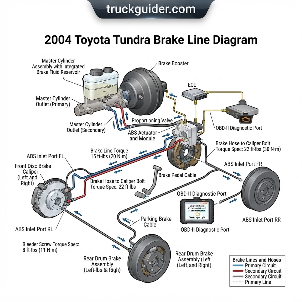
2004 Toyota Tundra Brake Line Diagram and Component Layout


Analyzing the primary hydraulic circuit of the 2004 Tundra reveals a directional architecture designed to balance front-to-rear hydraulic clamping forces under varied payload states. As shown in the diagram above, line routing originates at the engine firewall and splits across chassis-mounted junction blocks before interfacing with active wheel-end assemblies.



Primary Hydraulic Generation: Brake Master Cylinder and Booster


The hydraulic source begins at the tandem tandem-piston brake master cylinder, mounted to a dual-diaphragm vacuum assist brake booster bolted directly to the driver-side firewall. The master cylinder body features an integrated fluid reservoir equipped with an internal fluid-level reed switch that signals the instrument cluster brake indicator. Two primary outlets exit the side of the master cylinder body, threaded for M10x1.0 inverted flare nuts. The forward primary port delivers pressurized hydraulic volume dedicated to front axle braking circuits, while the secondary rearward port supplies fluid targeted for the rear axle assembly. In non-VSC (Vehicle Stability Control) models, these lines route directly into the ABS modulator block; on models equipped with active VSC, the circuit integrates secondary inline pressure transducers that report real-time line pressure directly to the skid control ECU.
Anti-Lock Modulation: ABS Actuator and Hydraulic Control Unit
Located on the passenger-side front inner fender apron sits the ABS Actuator and Hydraulic Control Unit (HCU). This electro-hydraulic block contains an array of normally open inlet and normally closed outlet solenoid valves, an electric motor-driven return pump, and dual low-pressure accumulators. The HCU receives the two independent feed lines from the master cylinder and divides the circuit into three or four dedicated output channels, depending on options packages. Two separate hard lines exit the top surface of the HCU to supply the front driver-side and front passenger-side four-piston calipers via frame-mounted bracket junctions and reinforced synthetic rubber flex hoses. The remaining hydraulic output descends down the inner fender to feed the rear brake circuit along the passenger frame rail.
Longitudinal Routing: Chassis Hard Brake Lines Along the Frame Rails
The longitudinal line path routes rigid steel tubing along the chassis rails, utilizing plastic isolation retaining clips pressed into pre-drilled frame apertures. From the ABS HCU, the rear hydraulic feed line traverses beneath the engine crossmember—shielded from thermal radiation off the exhaust manifolds—before joining the main frame bundle along the right (passenger) frame rail on standard configurations, or crossing to the driver-side rail adjacent to the fuel tank. These chassis hard brake lines operate at fluid pressures reaching 1,500 to 2,000 PSI under severe panic stops. The run features integrated vibration dampening coils (pigtail spirals) located immediately below the master cylinder and adjacent to the HCU to absorb structural frame deflection without fatiguing the steel tube wall.
Dynamic Rear Biasing: Load Sensing Proportioning and Bypass Valve (LSP&BV)


Unlike modern vehicles relying exclusively on Electronic Brakeforce Distribution (EBD), the 2004 Tundra incorporates a chassis-mounted mechanical hydraulic regulator: the Load Sensing Proportioning and Bypass Valve (LSP&BV). Mounted to a structural crossmember forward of the rear differential, the valve connects to the rear axle housing via a mechanical coil spring and shackle bracket. The valve body receives two hydraulic hard lines from the front of the vehicle: a main feed line and a return/bypass line. As payload inside the truck bed compresses the rear leaf springs, the mechanical linkage changes the internal valve plunger height, progressively permitting higher hydraulic line pressure to reach the rear drum wheel cylinders before cut-off, preventing premature rear wheel lockup under unladen conditions.


On 2004 Tundra models equipped with the factory towing package, the LSP&BV spring calibration differs slightly from base Regular Cab configurations. If you adjust or replace the rear axle drop bracket, you must measure the free length of the load sensing spring with the truck sitting on a level surface at curb weight; incorrect adjustment directly upsets rear brake bias and extends stopping distances.
Brake Line Specifications, Flare Geometry, and Torque Spec Table


Fabricating replacement brake hard lines for the 2004 Tundra requires strict adherence to Japanese Industrial Standard (JIS) mechanical design parameters. Modifying lines with mismatched thread pitches or incorrect seating flares causes structural leaks and catastrophic pressure loss under high pedal loads.
| Component / Fastener Location | Thread Pitch & Size | Flare Geometry | Tubing Outer Diameter | Factory Torque Spec |
|---|---|---|---|---|
| Master Cylinder Outlet Ports | M10 x 1.0 | 45-Degree Inverted (Double) | 3/16 in (4.75 mm) | 15 Nm (11 ft-lbs) |
| ABS Actuator Port Fittings | M10 x 1.0 | 45-Degree Inverted (Double) | 3/16 in (4.75 mm) | 15 Nm (11 ft-lbs) |
| Front Flexible Hose Banjo Bolts | M10 x 1.0 | Crush Washer / Banjo | N/A (Flex Hose) | 30 Nm (22 ft-lbs) |
| Front Caliper Bleeder Screws | M10 x 1.0 | Tapered Seat | N/A | 11 Nm (8 ft-lbs) |
| LSP&BV Input / Output Ports | M10 x 1.0 | 45-Degree Inverted (Double) | 3/16 in (4.75 mm) | 15 Nm (11 ft-lbs) |
| LSP&BV Bleeder Screw | M7 x 1.0 or M8 x 1.0 | Tapered Seat | N/A | 8 Nm (71 in-lbs) |
| Rear Drum Wheel Cylinders | M10 x 1.0 | 45-Degree Inverted (Double) | 3/16 in (4.75 mm) | 15 Nm (11 ft-lbs) |
Tubing Material: Copper-Nickel (NiCopp) vs. OEM Coated Steel
The original equipment hydraulic hard lines consist of low-carbon seamless steel coated with a fluororesin and zinc terne barrier. While structurally sound when newly produced, this multi-layer protection degrades under road de-icer exposure. When bending replacement hard lines, technicians prefer 90-10 Copper-Nickel alloy (UNS C70600, commercially known as NiCopp). NiCopp meets SAE standard J1047 and ISO 4038 for burst pressure requirements—rated well above 6,000 PSI in 3/16-inch diameters—while remaining completely impervious to galvanic and rust oxidation. Copper-nickel lines also flare and seat into the aged brass junction blocks without galling the M10x1.0 internal threads.
Flaring Standards: JIS Metric Double Flare Mechanics
Toyota braking components utilize a 45-degree SAE/JIS inverted double flare configuration with an M10x1.0 concave male tube nut. Do not confuse this with European DIN/ISO bubble flares (which feature a convex ball-shaped end and a 90-degree flat collar). Forcing a bubble flare into a Toyota master cylinder, caliper, or LSP&BV junction block will crush the seating land, generating fluid leaks that cannot be resolved by applying excessive tightening torque.


Wheelbase Tubing Dimensions across Cab Configurations
Total longitudinal tubing length varies based on the vehicle wheelbase. The 2004 Tundra was assembled in three core footprints:
- Regular Cab / Short Bed: 128.3-inch wheelbase. Single chassis rail hard-line length of approximately 142 inches from the forward engine bay down-junction to the rear axle drop point.
- Access Cab: 128.3-inch wheelbase. Retains identical frame hard-line routing as the Regular Cab, utilizing factory pre-bent lines with part number 77201-series prefixes.
- Double Cab: 140.5-inch wheelbase. Features an elongated frame box section requiring an additional 12.2 inches of hydraulic line length. The chassis hard brake lines on Double Cabs feature a revised center carrier bracket to suppress hydraulic line vibration over the extended span.
Factory hydraulic fluid specification: DOT 3 glycol-based hydraulic brake fluid. Dry system fluid capacity across all cab styles is approximately 1.1 liters (1.16 quarts). Maintain an equilibrium reflux boiling point (ERBP) of minimum 205°C (401°F). DOT 4 fluid is chemically compatible, but DOT 5 silicone fluid is strictly prohibited due to seal incompatibility inside the ABS HCU.
2004 Tundra Brake Line Diagram Failure Points and Frame Rust Hotspots


The first-generation Tundra is structurally susceptible to localized corrosion, an issue historically documented under the Toyota Frame Rust Recall (Safety Recall Campaign A0F/CSJ). While campaign protocols prioritized boxing crossmembers and subframe weld seams, hydraulic hard brake lines situated along those identical paths suffer severe premature deterioration.
The Fuel Tank Choke Point


The primary area of catastrophic line rupture occurs on the inboard face of the left-hand (driver-side) frame rail directly between the forward mounting strap of the fuel tank and the vehicle bed crossmember. Road spray containing calcium chloride enters the 0.75-inch clearance space between the fuel tank plastic shell and the steel frame channel. Road silt packs tightly inside this pocket, forming an abrasive, moisture-retaining poultice over the factory coated hard lines. Because this zone is invisible during casual underbody inspections without lowering the fuel tank assembly, corrosion degrades the steel wall until sudden pedal pressure blowouts occur during panic stop situations.
LSP&BV Corrosion and Seized Bleeder Screws
Positioned directly in the vortex of turbulent airflow generated by the rear axle assembly, the Load Sensing Proportioning and Bypass Valve operates in a relentless spray of grit and water. The internal iron valve body suffers from galvanic oxidation where the M10x1.0 steel flare nuts thread into the casing. Furthermore, the specialized miniature bleed screw on the top of the valve casing routinely seizes. Attempting to rotate this bleed screw without applying inductive heat frequently snaps the fitting flush with the valve housing, requiring full assembly replacement.



Corrosion frequently hides behind plastic snap-in frame retention clips. While exposed brake line runs appear structurally sound, salt crystals settle behind the clip brackets, eating away the line wall thickness from the frame side outward. Remove and inspect every individual chassis clip during diagnostic evaluations.
Rear Axle Housing Jump Lines and Drop Hoses
Hydraulic pressure travels from the stationary frame to the dynamic rear axle housing through a single flexible high-pressure drop hose. Over years of suspension articulation, the internal braided elastomeric lining of this drop hose fatigues. It can develop internal structural flaps that behave like one-way check valves—retaining pressure inside the rear drum wheel cylinders and overheating the brake friction material. Additionally, the rigid metal “T-junction” block located on top of the driver-side axle tube frequently rusts where the hard lines branch out laterally across the axle tubes to the drum backing plates.
Diagnosing Hydraulic Leaks and ABS Diagnostic Code Faults via OBD-II


Isolating mechanical hydraulic pressure losses from internal electronic actuator faults requires a disciplined diagnostic progression. Much like testing dynamic engine oil pressure, troubleshooting hydraulic brake degradation requires verified line pressure measurements paired with electronic diagnostic scans.
- Static Pedal Creep and Hydraulic Integrity Test: Begin with the vehicle stationary and engine running to supply engine vacuum to the brake booster. Depress the brake pedal using roughly 70 lbs of foot force for 60 seconds. If the pedal slowly sinks toward the floorboards, an active hydraulic leak is present. Visually inspect every junction outlined in the system diagram: master cylinder mounting flange (checking for fluid weeping through the booster front seal), ABS HCU manifold base, frame line rails, and the inner backing plates of the rear drum assemblies.
- Master Cylinder Internal Bypass Isolation: If the pedal sinks steadily under continuous force but zero exterior fluid leakage appears at any fitting or line run, the master cylinder is experiencing internal piston seal bypass. Hydraulic fluid slips backward past the primary piston cup rubber seals into the low-pressure reservoir chamber. Confirm this condition by safely installing threaded M10x1.0 brass isolation plugs directly into the two master cylinder outlets; if the pedal remains completely high and rigid with the ports isolated, the master cylinder internals are functioning properly, indicating an issue downstream in the ABS actuator or chassis line run.
- ABS Diagnostic Interrogation via OBD-II Port: Connect a professional scan tool to the OBD-II diagnostic port (DLC3) located under the lower driver-side instrument panel. Access the Skid Control ECU / ABS module to check for active diagnostic trouble codes (DTCs). If an electrical solenoid failure or abnormal pressure differential occurs within the ABS HCU, the system illuminates the ABS light, VSC TRAC light, and frequently commands a check engine light illumination through unified powertrain communications. Check for codes including:
- DTC C0200 / C0205: Front Right / Left Wheel Speed Sensor Circuit Fault.
- DTC C0210 / C0215: Rear Right / Left Wheel Speed Sensor Malfunction.
- DTC C1223: ABS Control System Malfunction (Indicating general hydraulic control failure).
- DTC C1246: Master Cylinder Hydraulic Pressure Sensor Circuit Performance.
- ABS Actuator Solenoid and Return Pump Mechanical Validation: If the system displays hydraulic instability only during hard stops or ABS cycling events, command an automated bleed/actuator purge test through your scan tool. Listen for uniform activation of the internal solenoid valves. An internal debris obstruction inside an ABS HCU solenoid seat causes localized pressure drops that mirror a blown hydraulic hard line, without exterior fluid loss.
- Rear Axle Drop Hose and Backing Plate Inspection: Elevate the rear axle on jack stands. Inspect the rubber drop line for ballooning under heavy hydraulic line pressure. Remove the rear brake drums and inspect the wheel cylinder dust boots. Carefully pry back the rubber lip of the wheel cylinder boot with a flat blade pick; any fluid accumulation behind the rubber seal signifies degraded piston cups, demanding immediate cylinder rebuilding or total replacement.
During vehicle service overhauls—such as evaluating the timing chain or timing belt tolerances on the 4.7L 2UZ-FE V8, auditing radiator coolant flow, or testing engine oil pressure senders—inspecting the condition of your hydraulic brake plumbing should be treated as an essential safety inspection.
Bleeding Sequence for the 2004 Toyota Tundra Brake Hydraulic System
Bleeding a first-generation Tundra equipped with the mechanical Load Sensing Proportioning and Bypass Valve requires a non-standard procedural order. Diverging from the traditional “furthest-to-closest” standard sequence will leave air bubbles trapped within the rear hydraulic loop, causing poor pedal feel and excessive pedal travel.
The hydraulic bleeding sequence for the 2004 Tundra must strictly follow this path:
- Load Sensing Proportioning and Bypass Valve (LSP&BV): Bleed the valve body mounted at the rear crossmember first. This step purges trapped air from the long, continuous chassis run originating at the ABS HCU before that air can enter the axle split lines.
- Rear Passenger-Side Drum Wheel Cylinder: Bleed the cylinder furthest along the dynamic axle hard line.
- Rear Driver-Side Drum Wheel Cylinder: Bleed the opposite drum wheel cylinder across the top of the axle casing.
- Front Passenger-Side Caliper: Bleed the front wheel-end furthest from the engine firewall master cylinder.
- Front Driver-Side Caliper: Complete the sequence at the wheel cylinder closest to the hydraulic source.
When executing manual two-person bleeding, fill the master cylinder reservoir to the MAX fill line with fresh, uncontaminated DOT 3 brake fluid. Attach a clear vinyl hose over the LSP&BV bleeder screw and submerge the opposing end into a transparent vessel filled with fresh fluid. Depress the brake pedal through three full down-strokes, hold the pedal flat against the floor, crack open the bleed screw 180 degrees using a flare nut wrench, observe fluid flow until velocity stops, tighten the bleeder screw, and slowly release the pedal.
Repeat this bleeding process until clean fluid passes through the drain line without micro-bubbles. Pay close attention to the fluid reservoir level throughout; if the fluid level drops below the MIN line during bleeding, the master cylinder bore will draw in air, requiring you to perform a full bench bleed of the primary master cylinder casting before restarting the process.
2004 Toyota Tundra Brake Line Diagram Technical Inquiries
What flare type is used on 2004 Toyota Tundra brake lines?
The 2004 Toyota Tundra exclusively utilizes 45-degree Japanese Industrial Standard (JIS) SAE inverted double flares across all hard line junctions. This includes the master cylinder, ABS Hydraulic Control Unit, frame rail junction fittings, LSP&BV proportioning block, and drum wheel cylinders. European DIN/ISO bubble flares are incompatible with these seats; threading a bubble flare into these female ports will crush the internal seating surface and cause permanent hydraulic leaks under pressure.
Why does my 2004 Tundra brake pedal sink even with no visible external leak?


If the brake fluid level inside the master cylinder reservoir remains stable but the pedal sinks steadily to the floor under holding pressure, the brake master cylinder has failed internally. The rubber primary and secondary piston seals inside the polished master cylinder bore have degraded, allowing pressurized fluid to bypass the piston cups and return to the low-pressure supply chamber. Alternatively, an internal ABS HCU valve that is mechanically stuck open can bypass fluid internally into an accumulator without venting any fluid to the ground.
Can I delete the Load Sensing Proportioning Valve (LSP&BV) when replumbing?
While some aftermarket off-road fabricators bypass the LSP&BV by installing a universal manual screw-type proportioning valve, doing so on a road-driven 2004 Tundra introduces substantial safety liability. The OEM valve actively alters rear line pressure relative to truck bed payload weight. Deleting the assembly or plumbing the rear lines straight through will cause extreme rear wheel lockup under moderate braking in an unladen bed state, potentially inducing an uncontrolled vehicle spin.
Does bleeding the brake lines trigger an ABS diagnostic code or check engine light?
Manual bleeding with the vehicle ignition switched completely off will not trigger fault codes in the skid control ECU. However, if the ignition switch is cycled to the ON position while lines are dry or cracked open, the ECU master cylinder pressure sensor registers an implausible pressure differential relative to the brake switch circuit. This mismatch logs DTC C1246 along with related wheel-circuit errors, illuminating the ABS indicator and occasionally setting an engine-chassis fault across the OBD-II bus.
What diameter tubing should I use to re-line the rear frame runs?
Use standard 3/16-inch outer diameter (OD) hydraulic tubing—measuring approximately 4.75 mm—matched with M10x1.0 metric male tube nuts. Never upsize or downsize line diameters along the frame rails. Changing tubing volume alters hydraulic fluid speed, shifting hydraulic apply volume between the front four-piston calipers and rear wheel cylinders, which compromises engineered stopping distances.
Step-by-Step Guide to Understanding the 2004 Toyota Tundra Brake Line Diagram
Identify – Inspect the master cylinder output ports and trace line markings to distinguish the primary front circuit from the secondary rear circuit.
Locate – Find the ABS hydraulic actuator along the inner engine bay fender and locate the chassis junction blocks along the left frame rail.
Reference – Match physical line bends, mounting bracket clips, and flexible hose transitions directly against the chassis routing schematic.
Connect/Route – Thread hardline ends by hand into the flare seats to prevent cross-threading, tightening fittings to the 11-13 ft-lbs torque spec.
Verify – Connect an OBD-II diagnostic tool, scan for any stored diagnostic code, command an ABS cycle, and verify firm hydraulic pedal resistance.
Troubleshoot – If a check engine light or ABS indicator appears, inspect flare seats for weepage, verify line port positions at the ECU-controlled module, and re-bleed the circuit.
2004 Toyota Tundra Brake Line Diagram: Frequently Asked Questions
What does the 2004 toyota tundra brake line diagram show?
The diagram maps hydraulic line paths originating from the master cylinder reservoir down to the ABS module. It details routing along the inner chassis rails to the front wheel wells, as well as the dual lines running rearward to the chassis-mounted load-sensing proportioning valve and flexible caliper hoses.
How do I read the 2004 toyota tundra brake line diagram?
Begin at the primary and secondary master cylinder ports, tracing the lines into the ABS hydraulic control unit ports marked MC1 and MC2. Follow output channels designated for front-left (FL), front-right (FR), and the rear tandem lines, referencing the color-coded flow indicators to track circuit direction.
What are the main components in 2004 toyota tundra brake line diagram?
Key components include the vacuum brake booster, dual-reservoir master cylinder, ABS hydraulic actuator, rigid 3/16-inch steel chassis lines, flexible reinforced rubber end-hoses, and the rear load sensing proportioning valve. The diagram also illustrates line brackets, junction blocks, and bleeder screw locations on each wheel caliper.
What are common problems with 2004 toyota tundra brake line diagram?
Common issues include severe road-salt corrosion along the driver-side mid-frame rail, rounded flare nuts, and internal rubber hose collapse. Hydraulic line pressure drops frequently trigger a check engine light or ABS warning light, prompting the skid control ECU to store a hydraulic malfunction diagnostic code via the OBD-II interface.
Can I use 2004 toyota tundra brake line diagram for DIY repair?
Yes, the diagram enables accurate routing of pre-bent replacement hardlines or custom nickel-copper (NiCopp) lines. However, technicians must adhere to line-clamping intervals, avoid cross-threading fragile aluminum ABS ports, and follow proper bleeding sequences to ensure no residual air causes spongey pedal travel or ECU-monitored pressure faults.
What tools do I need for 2004 toyota tundra brake line diagram?
Essential tools include 10mm flare nut wrenches, line benders, a double-flaring tool kit, and an accurate inch-pound torque wrench for fittings. An OBD-II scan tool capable of ABS automated cycling is recommended to purge trapped air from the ABS actuator block during post-installation system bleeding.