1999 Toyota Tacoma Parts Diagram: Component Breakdown 2026

The 1999 Toyota Tacoma parts diagram details major assemblies across the 2.4L (2RZ-FE), 2.7L (3RZ-FE), and 3.4L (5VZ-FE) powertrains, suspension geometry, and electrical harnesses. It maps OEM schematics from front bumper to rear axle, highlighting critical component structure, chassis mounting points, fastener torque values, and vacuum hose system layouts.
📌 Key Takeaways
- Engine schematics differ significantly between 4-cylinder timing chain designs and 3.4L V6 timing belt setups (90,000-mile interval).
- Chassis layout diverges between standard 5-lug 2WD models and 6-lug PreRunner/4WD front suspension configurations.
- Front lower ball joint bolts require 37 lb-ft of torque and medium threadlocker to prevent hazardous separation.
- High-frequency failure areas include lower ball joints, steering rack guide bushings, and mid-frame structural rust.
- Routine component bolt-ons are DIY-accessible, but structural frame reinforcement and differential re-gearing warrant professional service.
Navigating the factory catalog for a first-generation (1995.5–2004) Toyota compact pickup requires precision, particularly when referencing a 1999 toyota tacoma parts diagram. The 1999 model year represents a pivotal mid-cycle transition across the N140 (2WD base), N150 (2WD PreRunner), and N160/N170 (4WD) chassis platforms. Whether you are rebuilding a front double-wishbone suspension, identifying electrical harness sub-assemblies, or cross-referencing emissions-related hardware between California and Federal iterations, exploded schematics serve as the ultimate blueprint. The following technical analysis breaks down the major mechanical assemblies, catalog numbering logic, and structural variations essential for maintaining, repairing, and restoring the 1999 platform to original equipment manufacturer (OEM) tolerances.


Primary Schematic Reference: 1999 Toyota Tacoma Master Exploded Assembly (Chassis, Powertrain, and Running Gear Layout)
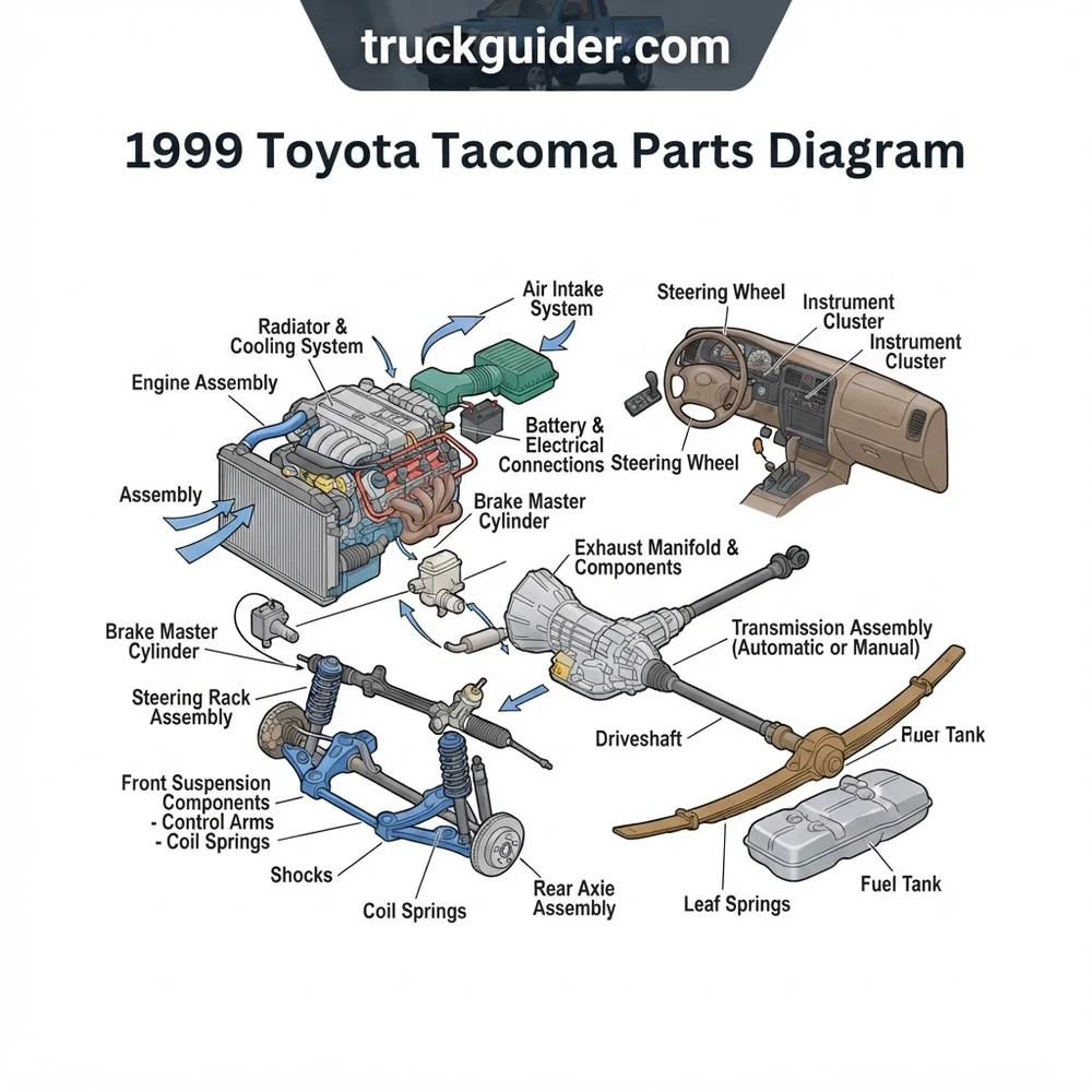
1999 Toyota Tacoma Parts Diagram: Core System Breakdown

In the official Toyota Electronic Parts Catalog (EPC), components are indexed by assembly systems. Understanding how mechanical groups correlate to physical sub-assemblies prevents ordering errors caused by production date cutoffs and trim divergence.
Front Suspension and Steering Assembly Layout

The front suspension architecture on the 1999 Tacoma bifurcates based on driveline configuration. Four-wheel-drive (4WD) and PreRunner models employ a high-clearance, double-wishbone design featuring an independent upper control arm (UCA), a coil-sprung lower control arm (LCA), and a steering knuckle supported by a lower ball joint configured in tension. Base 5-lug models use an inverted layout with compression-loaded ball joints and front-mounted steering tie rods. When examining the front suspension schematic, identify the lower ball joint assembly (PNC 43330 for right-hand; PNC 43340 for left-hand) and verify the mounting flange footprint, as bolt thread pitches and shank lengths changed across the first-generation lifecycle. Technicians undertaking a comprehensive front-end rebuild should also consult our dedicated chassis component overhaul reference for bushing press fit specifications.
Lower Ball Joint Attachment Bolts (4 per knuckle): 59 ft-lb (80 N·m). Toyota mandates the application of medium-strength thread-locking compound (Loctite 242 equivalent) and torque application exclusively to OEM micro-encapsulated flange bolts (P/N 90105-10406). Lower Ball Joint Castle Nut: 103 ft-lb (140 N·m) secured with a new stainless steel cotter pin.
Powertrain and Engine Assembly Blueprint
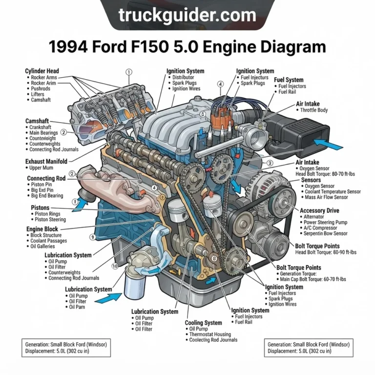
The 1999 Tacoma parts catalog documents three distinct internal combustion powerplants: the 2.4-liter inline-four (2RZ-FE), the 2.7-liter inline-four (3RZ-FE), and the 3.4-liter double overhead cam V6 (5VZ-FE). The engine schematic isolates the short-block assembly (PNC 11400) from the cylinder head (PNC 11101), timing gear train, and induction sub-systems. On 5VZ-FE applications, pay strict attention to the timing belt layout (PNC 13568, OEM base 13568-YZZ03). The schematic details the mechanical relationship between the crankshaft sprocket, dual camshaft sprockets, hydraulic tensioner (PNC 13540), and the dynamic idler pulleys. A critical variation in the 1999 blueprint involves the ignition trigger setup: while early first-generation Tacomas used a distributor or twin wasted-spark coils, the 1999 model year solidifies the three-coil pack architecture with wasted-spark secondary leads (PNC 90919-02212) serving opposing cylinders (1-4, 2-5, 3-6) on the V6 platform.
Drivetrain and Transfer Case Assembly Schematic
Driveline transfer for 4WD models centers on the VF1A (manual shift) or the vacuum/actuator-controlled Automatic Disconnecting Differential (ADD) system. The transfer case exploded view details the two-speed planetary gear set, shift rails, and electronic 4WD position switches. The front propeller shaft (PNC 37140) integrates a constant velocity (CV) joint assembly, while the two-piece rear driveshaft assembly utilizes a center support bearing (PNC 37230, base P/N 37230-35130). Inspecting the schematic reveals that dynamic balance is maintained via dual double-cardan universal joint yokes. When replacing U-joints or servicing the center carrier, driveline phase angles must align precisely with the stamped orientation marks indicated in the blueprint.
Hydraulic Brake System Layout and Components
The 1999 hydraulic brake schematic differentiates significantly between Anti-Lock Brake System (ABS) and non-ABS configurations. The non-ABS schematic maps an unassisted dual-chamber master cylinder (PNC 47201) routing directly through a frame-mounted Load Sensing Proportioning and Bypass Valve (LSP&BV) positioned above the rear axle housing. The LSP&BV dynamically modulates hydraulic line pressure to the rear duo-servo drum brakes (PNC 47050/47060) based on vehicle payload compression. On ABS-equipped 1999 models, the schematic incorporates a four-channel electronic hydraulic actuator assembly (PNC 44510) and wheel speed sensor routing harnesses (PNC 89542/89543). Front brake schematics depict dual-piston or four-piston cast-iron calipers (PNC 47730/47750), with 6-lug platforms utilizing the heavy-duty S13WB casting accommodating thicker 20mm vented brake rotors.
| Sub-Assembly System | Part Name Code (PNC) | Base OEM Reference | Critical Torque / Engineering Spec | System Function & Notes |
|---|---|---|---|---|
| Lower Ball Joint (RH) | 43330 | 43330-39585 | 59 ft-lb (Bolts) / 103 ft-lb (Nut) | Carries tension load between spindle and LCA on 6-lug chassis |
| Timing Belt (5VZ-FE) | 13568 | 13568-YZZ03 | Tensioner bolt: 20 ft-lb (27 N·m) | Synchronizes crank to dual cam sprockets; 281-tooth count |
| Driveshaft Center Bearing | 37230 | 37230-35130 | Crossmember bracket: 27 ft-lb | Isolates high-frequency driveline vibration on two-piece shafts |
| Front Brake Caliper (RH) | 47730 | 47730-35080 | Caliper mounting bolts: 90 ft-lb | 4-piston fixed caliper (S13WB casting) for 6-lug platforms |
| LSP&BV Assembly | 47910 | 47910-35270 | Brake line flare nut: 11 ft-lb | Mechanically regulates rear brake bias relative to axle travel |
Chassis and Drivetrain Configuration: 5-Lug vs. 6-Lug Schematics
The single greatest point of failure when navigating a 1999 toyota tacoma parts diagram is confusing the two primary chassis platforms. Toyota split the first-generation Tacoma into entirely distinct mechanical architectures: the standard 5-lug utility chassis (2WD base) and the 6-lug heavy-duty chassis (incorporating both traditional 4WD configurations and the 2WD Tacoma PreRunner introduced in 1998).


The 5-lug configuration (RN02/N140 frame) employs a spring-under-axle rear leaf structure and a car-like low-clearance front double wishbone suspension. The front wheel hubs use a 5×114.3mm (5×4.5 inch) pitch circle diameter (PCD) bolt pattern. Steering linkage on the 5-lug chassis is positioned forward of the spindle centerline (front-steer), using lighter rack-and-pinion assemblies (PNC 44250) that mount directly to the crossmember using vertical hardware sleeves.
Conversely, 6-lug platforms (VZN160/170, RZN160/170) employ a high-riding, spring-over-axle rear layout and a 6×139.7mm (6×5.5 inch) PCD hub assembly. Crucially, the Tacoma PreRunner utilizes the identical frame rails, suspension linkages, steering geometry, and brake components as the true 4WD model. The front suspension on both PreRunner and 4WD configurations is rear-steer (outer tie rod ends mount aft of the spindle hub). Technicians referencing steering or suspension schematics for a 2WD truck must verify whether the chassis code begins with RZN140 (5-lug standard) or RZN150/VZN150 (6-lug PreRunner). Failure to identify this chassis designation leads directly to cross-catalog ordering errors, particularly with control arms, shock absorbers, spindles, and brake rotors. For additional driveline variations across rear differentials, refer to our first-generation Tacoma rear differential guide.
Do not purchase steering, suspension, or front brake components based on “2WD” designations in aftermarket or generic catalogs. The 1999 Tacoma PreRunner shares zero front suspension or brake geometry with the 5-lug 2WD base model. Always select components from the 6-lug/4WD parts diagram hierarchy for PreRunner chassis.
| Engineering Parameter | 5-Lug Base Chassis (RN02 / N140) | 6-Lug PreRunner Chassis (N150) | 6-Lug 4WD Chassis (N160 / N170) |
|---|---|---|---|
| Hub Pitch Circle Diameter | 5 x 114.3 mm (5 x 4.5 in) | 6 x 139.7 mm (6 x 5.5 in) | 6 x 139.7 mm (6 x 5.5 in) |
| Rear Axle Orientation | Spring-Under-Axle (SUA) | Spring-Over-Axle (SOA) | Spring-Over-Axle (SOA) |
| Steering Gear Geometry | Front-Steer (Tie rods forward of axle) | Rear-Steer (Tie rods aft of axle) | Rear-Steer (Tie rods aft of axle) |
| Front Lower Ball Joint Type | Compression loaded; integrated plate | Tension loaded; 4-bolt bolt-on flange | Tension loaded; 4-bolt bolt-on flange |
| Brake Caliper Configuration | Single/Dual-piston sliding caliper | 4-piston fixed caliper (S13WB) | 4-piston fixed caliper (S13WB) |
| Front Drive Components | None (Solid spindle / 2WD hub) | None (Dummy hub / unit bearing) | CV half-shafts, ADD differential / tube |
Cab configuration also impacts driveline blueprints. The 1999 Tacoma was produced exclusively in Regular Cab and Xtracab configurations (the four-door Double Cab was not introduced until the 2001 model year). Regular Cab models utilize a short, single-piece rear driveshaft, omitting the center carrier bearing entirely. Xtracab models require the two-piece segmented driveshaft containing an intermediate center support bearing (PNC 37230) mounted to a specific frame crossmember.
Navigating the 1999 Toyota Tacoma Parts Diagram Step-by-Step
Converting an exploded EPC schematic into an accurate, deliverable OEM part number requires an analytical approach. Toyota catalogs do not list direct 10-digit part numbers on the visual blueprint. Instead, they use intermediate callouts known as Part Name Codes (PNC). Follow this sequential process to navigate the catalog effectively.
- Extract the 17-Digit Vehicle Identification Number (VIN):
Locate the VIN plate affixed to the driver’s side inner door jamb (B-pillar) or visible through the lower edge of the driver-side windshield. Input this string into the Toyota EPC database. The VIN automatically filters build options: engine configuration (e.g., 5VZ-FE vs 3RZ-FE), transmission type (W59/R150F manual vs A340E/A340F automatic), interior trim code, and plant code (NUMMI Fremont plant indicated by a leading “4T” sequence). - Determine the Full Model Designation Code:
If searching without a direct VIN, decode the chassis plate stamped on the firewall. A typical 1999 6-lug code reads:VZN170L-CRMDKAB.- VZN170: Platform series (V6 engine, 4WD chassis).
- L: Left-hand drive orientation.
- C: Xtracab configuration (R = Regular Cab).
- R: Floor-shift automatic or 5-speed manual code indicator.
- M / P: Trim grade designation (DLX vs SR5).
- D: Double Overhead Cam (DOHC) multi-valve induction.
- K: Catalytic converter / emission control spec.
- A / B: Final assembly package variations.
Filtering via this model string eliminates 70% of non-matching catalog groups automatically.
- Isolate the EPC Functional Major Group:
Factory schematics are categorized into four core divisions:- Group 1 (Tool / Engine / Fuel): Mechanical blocks, cylinder heads, water pumps, fuel injection rails, and air intake manifolds.
- Group 2 (Powertrain / Chassis): Clutches, transmissions, transfer cases, differentials, leaf springs, upper/lower control arms, steering gears, and brake hydraulics.
- Group 3 (Body / Interior): Cab sheet metal, bed structural components, glass, interior dashboard moldings, weatherstripping, and seats.
- Group 4 (Electrical): Wiring looms, relays, fuse blocks, Engine Control Modules (ECM), switches, and lighting assemblies.
- Identify the Diagram Part Name Code (PNC):
Locate the mechanical component on the exploded line drawing. You will find a 5-digit callout number pointing to the component via an index arrow. For instance, in the front hub diagram, the callout for the wheel hub itself is 43502. This 5-digit sequence is universal across hundreds of Toyota models and indicates what the part is conceptually, but it is not an orderable SKU. - Cross-Reference the PNC into the Full 10- or 12-Digit OEM Part Number:
Select the PNC within the digital catalog interface to reveal the secondary table. The database will query your filtered VIN and return the full ten-digit OEM part number (or twelve-digit number if hyphenated with factory color or supersession suffixes). For our example, PNC 43502 resolves to 43502-35170 (for 6-lug applications) or 43502-04010 (for 5-lug applications). - Verify Production Date Breakpoints:
Check the date code displayed next to the part number listing (formatted as YYMM-YYMM). The 1999 model year encompasses vehicles manufactured from 08/1998 through 07/1999. If a part changed mid-year (for example, an emissions sensor change effective 01/1999), verify your vehicle’s physical assembly date stamped on the B-pillar tag before finalizing the part selection.
Toyota part numbers follow a strict alphanumeric architecture: XXXXX-YYYYY. The first 5 digits represent the base Part Name Code (PNC) matching the schematic group. The final 5 digits represent the design iteration, material specification, vehicle application family, or production vendor code.
Troubleshooting 1999 Tacoma Diagram Mismatches and Part Errors
Even seasoned automotive technicians encounter discrepancies when matching physical parts on a 1999 Tacoma to legacy schematics. These mismatches stem from factory recalls, mid-generation design revisions, and regional emissions architecture variations.


Lower Ball Joint (LBJ) Failure and Bolt Revision Supercession
The most safety-critical component mismatch on the 1999 Tacoma involves the front Lower Ball Joint (PNC 43330/43340). Because the 6-lug design places the ball joint in tension—continually pulling the ball stud outward from its housing during vehicle operation—the assembly experienced widespread failure issues that triggered extensive safety recalls. Factory parts diagrams often cross-reference older part numbers that have undergone multiple generations of supercession.
When reviewing the schematic, ensure you reject early historical part numbers (e.g., 43330-39315). The final, fully reinforced OEM revisions are 43330-39585 (RH) and 43340-39465 (LH). Furthermore, older schematics depict the four lower ball joint attachment bolts as conventional flanged bolts with split-lock washers (P/N 90119-10933). Toyota superseded this hardware with specialized, black-phosphate micro-encapsulated flange bolts lacking loose washers (P/N 90105-10406). Reusing old-style bolts or torque values from early 1995–1997 shop manuals will result in fastener loosening, thread yield failure, and wheel separation.
California vs. Federal Emissions and Exhaust Schematic Discrepancies
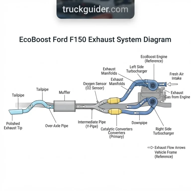
A frequent error occurs within the exhaust and emissions system schematics (Group 1: Fuel & Exhaust). During the 1999 model year, Toyota produced two wildly divergent emissions platforms: Federal Emissions (EPA) and California Emissions (CARB spec, which also applied to vehicles sold in select northeastern states).
- Federal Emissions Diagram: Displays a single oxygen sensor upstream of a single catalytic converter, and a secondary post-cat oxygen sensor downstream. Upstream sensor PNC 89465 resolves to an unheated or conventional heated zirconia O2 sensor (P/N 89465-35580).
- California Emissions Diagram: Incorporates dual catalytic converters and substitutes the upstream oxygen sensor with an advanced wideband Air/Fuel (A/F) ratio sensor (PNC 89467, resolving to P/N 89467-35011). The exhaust pipe routing, flange angles, and sensor bung thread designs are physically incompatible between these two variations.
Attempting to install a standard zirconia O2 sensor on a California-spec ECM will instantly trigger Diagnostic Trouble Codes (DTC) P0125 and P0135. Technicians diagnosing recurring engine codes should cross-reference our first-generation OBD-II trouble code and sensor guide to isolate harness fault conditions.
Before sourcing exhaust manifolds, downpipes, catalytic converters, or ECM harnesses, verify the under-hood Vehicle Emission Control Information (VECI) label. If the tag reads “Conforms to California regulations,” only order components through California-designated schematic diagrams, regardless of where the vehicle is currently registered.
Steering Rack Bushings and Guide Assembly Variances
The steering gear schematic (PNC 44250) for the 1999 model year frequently misleads technicians seeking individual rebuild components. The factory diagram shows the complete rack-and-pinion assembly as a single serviceable unit. However, the internal rack guide assembly—comprising the rack guide, spring, and cap—underwent a significant factory revision during 1999 to cure an inherent front-end popping sensation. The original roller-style guide was superseded by a low-friction teflon slipper-style brass guide (P/N 44236-35010). When consulting aftermarket exploded schematics, technicians frequently receive the round guide rather than the updated hexagonal housing casting, rendering adjustment impossible without the corresponding specialized service tool (SST 09612-00012).
1999 Toyota Tacoma Parts Diagram: Frequently Asked Questions
Where can technicians access factory-level 1999 Toyota Tacoma parts diagrams?
Professional technicians utilize Toyota’s Technical Information System (TIS) or official OEM electronic parts catalog portals that license raw relational databases from Toyota Motor Corporation. While third-party dealership web portals offer exploded line drawings, ensure the interface allows direct 17-digit VIN filtering to eliminate non-applicable chassis builds and market-specific variations.



Why does my 1999 Tacoma EPC diagram show two different oil filter part numbers for the 3.4L 5VZ-FE?
The EPC schematic displays two distinct filters due to historical Japanese factory supply lines versus North American port/dealer supply chains. The original Japanese factory blueprint calls out P/N 90915-20004 (a high-efficiency synthetic resin depth media filter). In North American service documentation, this number is superseded by P/N 90915-YZZD1 (or 90915-YZZD3 for higher-capacity fleet applications). Both match the 3/4-16 UNF-2B thread pitch and 14 psi bypass valve threshold required by the 5VZ-FE block.
How do I identify whether my 1999 Tacoma has an Automatic Disconnecting Differential (ADD) from the front axle schematic?
Look directly at the front differential carrier assembly in the EPC blueprint (Group 41: Front Axle Housing). An ADD-equipped platform contains an elongated driver-side intermediate axle tube housing an internal sliding splined clutch sleeve, governed by an electro-pneumatic vacuum actuator mounted directly to the tube (PNC 41400, P/N 41400-35020). A non-ADD manual front axle features symmetrical short axle tubes on both sides of the center cast housing and routes out to manual freewheeling locking hubs (PNC 43530) rather than fixed unit-bearing drive flanges.
What is the difference between Federal and California emissions layouts on the 1999 Tacoma parts schematic?
The California emissions schematic incorporates two separate inline catalytic converters (PNC 18450) and a wideband Air/Fuel ratio sensor (PNC 89467) positioned upstream of the first converter bed. The Federal schematic illustrates a single catalytic converter and utilizes a traditional zirconia oxygen sensor (PNC 89465) in both upstream and downstream positions. The physical exhaust manifolds and front exhaust downpipes cannot be interchanged between these two configurations.
Can I install manual locking hubs on my 1999 4WD Tacoma using factory parts diagrams?
Yes, but you cannot simply bolt the manual hub dials (PNC 43530) onto an ADD wheel hub. The parts diagram demonstrates that the front wheel spindle, wheel hub inner splines, and outer CV joint stub axles differ between ADD and manual-hub models. To convert an ADD truck to manual hubs using factory schematics, you must order the complete manual hub conversion group: manual-spec outer CV half-shafts (PNC 43430), manual wheel hubs (PNC 43502), and the freewheel hub clutch sub-assemblies (PNC 43530-60042).