2003 Ford F150 Front Suspension Diagram: 2026 Repair Guide

The 2003 Ford F-150 front suspension features upper and lower control arms with coil springs on 2WD models or torsion bars on 4WD setups. Upper ball joints are integrated into the control arm, while lower ball joints press into the knuckle, requiring a 111 lb-ft lower ball joint nut torque spec.
📌 Key Takeaways
- Lower ball joint castellated nut requires a 111 lb-ft (150 Nm) torque spec, while upper arm pivot bolts require 98-120 lb-ft.
- 2WD models employ standard coil springs over lower control arms, whereas 4WD variants utilize longitudinal torsion bars keyed to a rear crossmember.
- Always unload 4WD torsion bars with a dedicated mechanical unloading tool prior to disassembly to prevent dangerous uncontrolled decompression.
- Worn lower ball joints and snapped stabilizer bar end link bushings represent the primary failure points causing front-end clunking.
- Bushing, sway link, and shock replacements are DIY-accessible, but severe torsion bar rust or final alignment checks warrant professional shop equipment.
The tenth-generation Ford F-150 platform utilizes an independent front suspension (IFS) configuration designed to balance rugged load capacity with predictable road handling. Whether you are maintaining a two-wheel-drive (2WD) work truck or a four-wheel-drive (4WD) off-road model, interpreting the 2003 ford f150 front suspension diagram requires understanding how structural load paths, steering linkages, and dampening hardware interact under dynamic stress. This guide breaks down factory schematics, mechanical assemblies, torque specifications, and diagnostic inspection workflows for seasoned technicians and advanced DIY mechanics working on the 2003 model year and the carryover 2004 F-150 Heritage edition.
2003 Ford F150 Front Suspension Diagram: 2WD vs 4WD Layouts


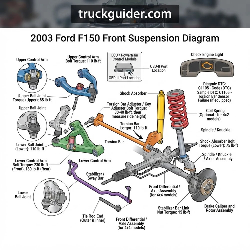
The 2003 Ford F-150 front suspension system relies on a Short/Long Arm (SLA) independent suspension architecture. However, the energy storage mechanism and steering delivery differ fundamentally depending on whether the truck is configured with rear-wheel drive or four-wheel drive. Reviewing the 2003 ford f150 front suspension diagram reveals two distinct structural footprints that cannot exchange primary sprung-mass components.

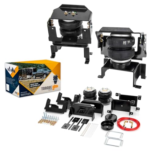


2WD SLA Coil Spring Configuration


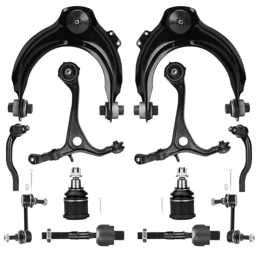
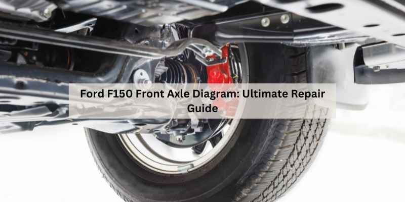
On two-wheel-drive models, vertical suspension compliance is managed by conventional helical front coil springs seated between an upper frame tower pocket and the deep spring pocket of the lower control arm (LCA). A twin-tube or monotube shock absorber is positioned concentrically down the center of the coil spring, securing to the lower control arm via a lower cross-pin mount and through the upper frame bracket with a threaded stem and isolator grommets.
Steering actuation on 2WD models is handled by an engine-crossmember-mounted rack-and-pinion steering assembly. This setup offers direct lateral input to the steering knuckles through inner and outer tie rod ends. The steering knuckles are engineered as cast-iron uprights featuring integrated spindles that accept tapered, serviceable inner and outer wheel bearings secured by a castled nut and cotter pin assembly.
4WD SLA Torsion Bar Configuration
Four-wheel-drive models eliminate the coil spring to accommodate front drive axles (half-shafts) routed from the front differential carrier to the front wheel hubs. Instead of coils, 4WD variants utilize longitudinal torsion bars as the primary spring medium. The forward hex-splined end of each torsion bar mates directly into the internal broached socket of the cast-steel lower control arm. The rearward end docks into an adjustable torsion key seated within an intermediate frame crossmember positioned beneath the cab.
Because the half-shaft passes directly through the operational zone where a concentric shock would typically sit, the 4WD shock absorber is relocated outboard, mounting to an integrated bracket on the lower control arm and an offset upper frame mount. Furthermore, the steering architecture shifts from a rack-and-pinion unit to a heavy-duty recirculating-ball steering gear. This design actuates a pitman arm, center link (drag link), frame-anchored idler arm, and individual tie rod assemblies. The steering knuckle is hollowed out to support a sealed, bolt-in hub and bearing unit equipped with integrated tone rings for ABS data collection by the powertrain control module and ECU.


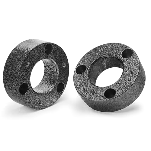

When ordering replacement parts using a 2003 ford f150 front suspension diagram, verify the 8th and 10th digits of your VIN. The 2004 Ford F-150 Heritage shares identical front-end geometry with the 2003 model year, whereas all-new 2004 eleventh-generation models transitioned to a coil-over-strut design across both 2WD and 4WD configurations. For related chassis work, review our guide on 10th-gen Ford truck drivetrain maintenance.
2003 Ford F150 Front Suspension Diagram: Component Functions and Torque Specs


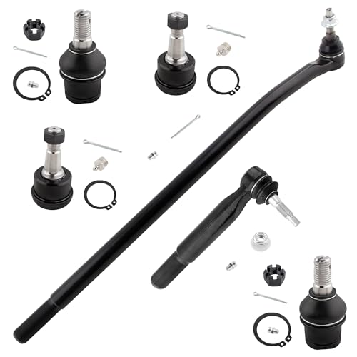

Every fastener within the 10th-generation front chassis serves an essential clamping function. Incorrect clamping forces introduce shear loads to ball studs and pivot bolts, leading to structural fatigue, alignment drift, or joint separation. Factory service manual guidelines mandate precise fastener tightening sequences.
| Component | Chassis Function & Location | Fastener Size & Factory Torque Spec |
|---|---|---|
| Upper Control Arm (UCA) Frame Pivot Bolts | Connects upper control arm bushings to upper frame pockets; controls caster and camber via eccentric alignment washers. | M14x2.0 Grade 10.9 Fastener 84-112 Ft-Lbs (114-152 Nm) |
| Upper Ball Joint to Knuckle Nut | Secures upper ball joint tapered stud to upper pinch aperture of the steering knuckle. | M12x1.75 Slotted / Flanged Nut 57-75 Ft-Lbs (77-103 Nm) |
| Lower Control Arm (LCA) Pivot Bolts (2WD) | Horizontal cross-bolts securing stamped LCA through engine cradle mounting tabs. | M16x2.0 Grade 10.9 Bolt 121-147 Ft-Lbs (164-200 Nm) |
| Lower Control Arm Pivot Bolts (4WD) | Cross-bolts anchoring cast-steel LCA to boxed frame drop brackets; withstands torsion preload. | M16x2.0 Grade 10.9 Bolt 121-148 Ft-Lbs (164-201 Nm) |
| Lower Ball Joint to Knuckle Nut | Heavy-taper load-carrying ball joint stud seated into lower receiver bore of knuckle. | M16x1.5 Castled Nut with Cotter Pin 83-112 Ft-Lbs (113-153 Nm) |
| Tie Rod End Jam Nut | Locks outer tie rod body to inner tie rod threaded shaft to maintain static toe angle. | Threaded Collar / Hex Nut 50-60 Ft-Lbs (68-81 Nm) |
| Outer Tie Rod to Steering Arm Nut | Tapered stud connecting outer tie rod to steering knuckle steering arm. | M14x1.5 Slotted Nut 51-67 Ft-Lbs (69-91 Nm) |
| Sway Bar Link Assembly Nut | Through-bolt retaining polyurethane or rubber isolation bushings to lower control arm. | M10x1.5 Locknut 15-21 Ft-Lbs (20-28 Nm) |
| Lower Shock Absorber Cross-Bolt (4WD) | Secures lower eyelet bushing of front shock to mounting flange on lower control arm. | M14x2.0 Through-Bolt 35-46 Ft-Lbs (47-63 Nm) |
| Upper Shock Absorber Stem Nut | Upper dampener mounting retention through frame tower bracket. | M10x1.25 Self-Locking Nut 25-34 Ft-Lbs (34-46 Nm) |
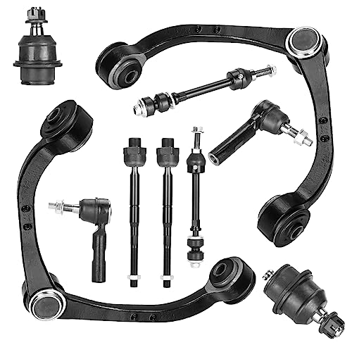
Factory upper ball joints are permanently swaged into the factory upper control arm. Replacement requires installing an entire upper control arm assembly. Conversely, lower ball joints are press-fit into the lower control arm and can be replaced independently using a heavy-duty C-frame ball joint press and correct receiver adapters. Always check fastener torque spec ratings before final assembly.
Failing 2003 Ford F150 Front Suspension Symptoms, Noises, and Diagnostic Codes


Degraded suspension components on the 2003 F-150 generate distinct acoustic and tactile feedback long before complete mechanical failure occurs. Mapping specific symptoms to parts on the front suspension schematic allows you to accurately target worn components.
Upper and Lower Ball Joint Degradation
Because the lower ball joint acts as the primary weight-bearing pivot on both 2WD and 4WD configurations, internal wear generates a distinctive, low-frequency dull metal “clunk” when traversing speed bumps, driveway transitions, or rough rail crossings. As grease seals rupture and the internal socket loses pre-load, axial free-play creates steering wander and uneven tire shoulder wear (typically outer edge scrub). A failing upper ball joint, which acts as a follower joint guiding steering axis inclination (SAI), produces dry, high-pitched metallic creaks or pops during slow-speed wheel turning or chassis lean.


Idler Arm, Center Link, and Tie Rod Deflection


On 4WD trucks equipped with the recirculating-ball steering linkage, the idler arm bracket supports the passenger-side drag link assembly. As the internal oil-impregnated bronze or plastic sleeve of the idler arm wears out, horizontal steering compliance increases significantly. Symptoms include excessive steering wheel dead-band (often two to three inches of unassisted wheel motion before tire response) and severe high-speed wheel shimmy between 45 and 60 mph.
Stabilizer Bar Bushing and Link Separation
The front anti-roll (stabilizer) bar operates under heavy torsional deflection during vehicle cornering. When the end link sleeves corrode or the through-bolt shears, a rhythmic rattling or clicking noise echoes from the wheel wells over small road ripples. Loss of the sway bar link directly compromises lateral body stability, leading to excessive chassis lean and imprecise steering recovery.
Chassis Influence on ECU and OBD-II Systems
While mechanical control arms do not connect directly to vehicle electronics, severe front-end looseness directly influences digital chassis management. Loose wheel bearings or excessive lower ball joint deflection disrupts the air gap between the front ABS variable reluctance sensor and the tone ring housed in the 4WD hub assembly.
When the air gap exceeds 0.050 inches due to mechanical spindle or bearing play, the sensor signal deteriorates. This triggers erratic wheel speed readings, prompting the anti-lock brake controller to illuminate the ABS dashboard indicator and register an OBD-II chassis trouble code (such as C1155 or C1145 for front left/right speed sensor circuit failure). In advanced failure modes, erratic wheel speed data transmitted to the central ECU disrupts shift timing or cruise control engagement, occasionally generating a check engine light accompanied by a transmission-related diagnostic code like P0500 (Vehicle Speed Sensor Malfunction). If your diagnostic scan points to powertrain or ignition faults, consult our guide on diagnosing Ford truck sensor and circuit faults.


How to Inspect Components on a 2003 Ford F150 Front Suspension Diagram


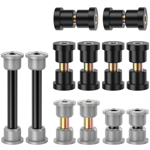

Proper diagnostic evaluation of the 2003 Ford F-150 front end requires isolating suspension components from mechanical spring preload. Applying incorrect lifting techniques will trap spring energy inside the ball joints, hiding significant lateral or axial wear.
- Elevate and Unload the Suspension Assembly Correctly:
- On 2WD Models: Position the hydraulic floor jack directly beneath the lower control arm spring pocket as close to the wheel as possible. Lift until the tire clears the deck by two inches. This unloads the coil spring tension from the upper ball joint while keeping the lower ball joint loaded under vehicle weight for stable inspection.
- On 4WD Models: Place the floor jack beneath the main frame rails behind the front wheels and raise the truck until the front tires droop completely, leaving the suspension in full rebound hanging free. Torsion spring tension must be unloaded from the steering knuckle to verify joint play. Support the frame securely on heavy-duty, rated jack stands.
- Measure Lower Ball Joint Axial and Radial End-Play: Attach a magnetic-mount dial indicator base to the lower control arm, placing the indicator plunger against the lowest flat spot of the steering knuckle casting. Insert a long steel pry bar beneath the front tire and apply upward leverage. According to Ford OEM technical service standards, if axial movement exceeds 0.030 inches (0.76 mm), or if visual radial play is evident at the dust boot perimeter, press out and replace the lower ball joint immediately.
- Inspect the Upper Control Arm and Integral Ball Joint: Grasp the top of the tire firmly with both hands, rocking it inward and outward along the 12 o’clock plane while observing the upper ball joint stud and pinch interface. Look for lateral movement within the upper arm socket. Next, inspect the two inner UCA cross-shaft rubber bushings; split rubber, dry rot, eccentric washer movement, or fluid contamination (frequently caused by remote oil filter adapter leaks or valve cover seepages) requires complete upper arm assembly replacement.
- Examine Steering Linkage, Idler Arm, and Tie Rod Ends: Grasp the tire at the 9 and 3 o’clock positions and cycle it back and forth using light, controlled force. An assistant should look for lost motion at the inner and outer tie rod ball pivots. On 4WD models, closely observe the idler arm pivot where it mounts to the passenger-side frame rail. Any visible vertical or rotational deflection of the idler arm bracket prior to center link movement indicates severe internal bushing wear.
- Inspect the Stabilizer Bar Bushings and End Links: Check the sway bar frame bushings for hardening, elongation, or lateral shifting along the bar. Examine the end link stacks: the long central bolt should be perpendicular to the lower control arm mount, and the polyurethane or rubber isolator biscuits must be uncracked and uniformly compressed without the steel washers contacting the link sleeve.
Under no circumstances should you attempt to loosen or remove the lower control arm pivot bolts or ball joints on a 4WD 2003 F-150 without first fully relaxing the torsion bar tension using a dedicated torsion bar unloading tool. Torsion bars store lethal rotational energy that will violently eject unbolted suspension components if disassembled under tension.
Servicing 2003 F-150 Torsion Keys, Alignment Geometry, and ECU Sensors
Servicing the 4WD front suspension on the 10th-generation F-150 requires specialized tools and strict adherence to safety protocols. Relieving the torsion bar requires an OEM-style torsion bar crossmember puller (Ford Specialty Tool T95T-5310-A or an equivalent forged C-clamp tool). Never attempt to unload the torsion bar keys using a standard two-jaw mechanical gear puller; the extreme torque load can cause the puller jaws to slip off the key dimple, resulting in catastrophic tool failure and severe technician injury.
Thread the tool center bolt up into the torsion key counterbore, advance the forcing screw until the pressure is removed from the lower keeper block, slide the keeper block out from the crossmember channel, and steadily back the forcing screw out until the torsion bar is entirely relaxed. Only then can the lower control arm, CV half-shaft, or steering knuckle be detached safely.
Following any control arm, ball joint, or tie rod replacement, you must complete a four-wheel alignment. Factory specifications for the 2003 F-150 require establishing baseline ride height (Z-height on 4WD torsion models) before locking down alignment angles:
- Camber: Target -0.25° to +0.25° (achieved via eccentric cam kits installed at the upper control arm frame bolts).
- Caster: Target +4.0° to +4.5° on 2WD; +4.2° to +4.7° on 4WD to ensure high-speed straight-line tracking.
- Total Toe: Set to +0.05° to +0.15° toe-in to prevent inner tire feathering.
Once alignment is complete, connect an OBD-II scanner to confirm that no ABS speed sensor faults or electronic steering control disruptions occurred during service. Technicians performing concurrent engine servicing—such as inspecting the Modular V8 timing chain guides, repairing front cover leaks, or verifying that adequate coolant flow and engine oil pressure are maintained across the front accessory drive—should ensure the front frame crossmembers are completely clear of tools, debris, and grease before releasing the vehicle.
Frequently Asked Questions: 2003 Ford F150 Front Suspension Diagram
Can I install 4WD torsion keys or torsion bars onto a 2WD 2003 Ford F-150?
No. The 2WD and 4WD 10th-generation F-150 models use fundamentally different frame structures and spring configurations. The 2WD frame features stamped upper spring towers and lower control arms designed specifically for helical coil springs. It lacks the broached lower control arm hex pockets, transmission-crossmember torsion key mounting brackets, and intermediate structural crossmembers required to install and support a longitudinal torsion bar system.
Why does my 2003 F-150 pull or wander after installing new upper control arms?


Unlike many modern light trucks with slotted or fixed alignment positions, the 10th-gen F-150 uses oversized frame slots for the upper control arm mounting bolts. From the factory, these bolts do not include fixed eccentric cams. When you loosen these bolts to replace the arm, the frame alignment position shifts completely. You must install an aftermarket camber/caster cam bolt lockout kit (featuring eccentric washers) and set the alignment angles on an optical alignment rack to restore straight-line stability.
Are the lower ball joints pressed into the steering knuckle or the lower control arm?
On all 2003 F-150 models (both 2WD and 4WD), the lower ball joint is pressed directly into the lower control arm casting or stamping, with the tapered stud pointing upward into the steering knuckle. The upper ball joint is integral to the upper control arm and cannot be pressed out separately; it must be replaced as a complete upper control arm assembly.
Can front suspension wear cause an ABS light or check engine light on my dash?
Yes. Excessive runout in the front wheel hub bearings, severe spindle play, or a loose lower ball joint allows the ABS tone ring to move out of alignment relative to the wheel speed sensor. When the sensor air gap fluctuates beyond tolerance, the ABS module detects signal distortion and sets a chassis diagnostic code, activating the ABS dash light. Signal loss can also interrupt vehicle speed data sent to the primary ECU, setting a vehicle speed sensor code and illuminating the check engine light.
Do I need an alignment if I only adjust the front torsion bar keys to level my 4WD truck?
Yes. Adjusting the torsion bar preload keys changes the static ride height of the front suspension. Because of the Short/Long Arm (SLA) suspension geometry, any change in ride height moves the upper and lower control arms through an arc. This directly alters both your static camber angle and toe setting. Increasing the ride height without performing an alignment causes excessive positive camber and significant toe-in, resulting in accelerated outside-edge tire wear within a few hundred miles.
Step-by-Step Guide to Understanding the 2003 Ford F150 Front Suspension Diagram
Identify – Verify your drive configuration (2WD coil spring or 4WD torsion bar) against the schematic to select the proper service procedure.
Locate – Position the truck on heavy jack stands and locate the lower control arm, steering knuckle, and stabilizer bar mounting points.
Reference – Consult the diagram to confirm hardware orientation, washer placement, and critical factory torque spec values for each fastener.
Connect/Route – Install replacement control arms or ball joints, seating taper pins securely into the spindle and routing ABS harness clips correctly.
Verify – Torque all chassis hardware to specified ratings under vehicle load and check wheel hub rotation to avoid triggering an ABS diagnostic code.
Troubleshoot – Test-drive to evaluate steering centering and alignment; scan via OBD-II if an unexpected check engine light or ABS fault illuminates.