2005 Ford F150 Fuel Line Diagram: Routing & Repair (2026)

The 2005 Ford F150 uses a returnless fuel system. The nylon supply line runs along the inner driver-side frame rail from the tank-mounted pump module through an inline fuel filter to the engine bay. It connects to the fuel rail pressure transducer at 35–45 PSI regulated via the Fuel Pump Driver Module.
📌 Key Takeaways
- Standard operating fuel rail pressure is 35 to 45 PSI regulated electronically by the FPDM.
- Quick-connect spring-lock couplings require 5/16-inch and 3/8-inch disconnect tools.
- The Fuel Pump Driver Module (FPDM) on the rear crossmember requires 10 Nm torque on reassembly.
- Corrosion between the aluminum FPDM and steel axle housing is the primary cause of sudden fuel loss.
- DIY line replacement is viable with pre-bent nylon kits, but drop the tank if sender collars seize.
Diagnosing delivery issues or replacing rusted plumbing on the eleventh-generation Ford F-150 requires a thorough understanding of Ford’s Electronic Returnless Fuel System (ERFS). Unlike older dual-line setups, the 2005 platform relies on variable pump speed and direct pressure monitoring to deliver precise fuel mass to the 4.2L Essex V6, 4.6L Romeo/Windsor V8, and 5.4L 3-Valve Triton V8 engines. Navigating the chassis plumbing demands an exact understanding of quick-disconnect fittings, vapor management lines, and localized electrical controllers. This technical reference breaks down the complete chassis routing, electrical integration, and physical components documented in the factory 2005 Ford F150 fuel line diagram.
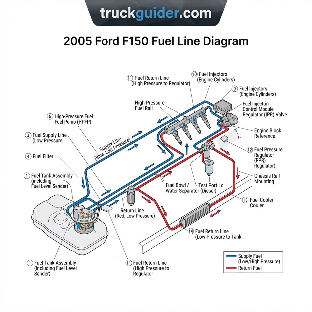
2005 Ford F150 Fuel Line Diagram: Routing and Architecture


The chassis layout depicted in the 2005 Ford F150 fuel line diagram represents a critical mid-generation engineering shift. The eleventh-generation (2004–2008) F-150 operates an Electronic Returnless Fuel System (ERFS). A single 3/8-inch outer diameter (OD) nylon-jacketed steel and braided flex main fuel supply line runs from the in-tank pump module directly to the engine bay fuel rail. Understanding this layout requires examining how fuel routing evolved across Ford truck generations.


In the preceding 1997–2003 Ford F-150 fuel system (tenth-generation), engineers utilized a continuous mechanical loop. A primary feed line delivered high-volume fuel to the engine, while a dedicated fuel return line carried unburned, hot fuel from a manifold-referenced mechanical fuel pressure regulator back down the driver-side frame rail into the fuel tank. That legacy system required an external fuel cooler in heavy-duty or diesel variants to lower fuel tank temperatures and reduce fuel aeration. By 2005, Ford eliminated the mechanical fuel return line entirely, alongside the external fuel cooler and tank-side return ports.
Unlike legacy diesel fuel systems that utilize a frame-mounted fuel bowl, an auxiliary primer pump, and a PTC-element fuel heater to condition high-viscosity fuel, the 2005 gasoline F-150 relies entirely on an in-tank gerotor pump. The variable-speed pump modulates output dynamically to manage line pressure without recirculating fuel.
Tracing the 2005 F-150 chassis routing reveals two primary parallel conduits along the inside channel of the left-hand (driver-side) boxed frame rail: the high-pressure main fuel supply line and the Evaporative Emission (EVAP) vapor purge lines. Beginning at the sender hat on the fuel tank (available in 27-gallon standard or 35.7-gallon extended options), the main 3/8-inch high-pressure line exits via a 90-degree push-to-connect fitting. It runs forward along the frame rail, secured by molded nylon retaining brackets spaced roughly every 18 to 24 inches.
Approximately midway along the inner frame rail, directly beneath the driver-side cab door, the line enters an inline canister fuel filter. Exiting the filter, the line transitions from rigid steel tubing to a flexible, fluoropolymer-lined braided hose. This flex section bridges the chassis-to-body vibration gap as the line travels upward along the transmission tunnel and driver-side bulkhead. At the rear engine bulkhead, the line mates to the driver-side fuel rail via a spring-lock coupling or push-connect safety retainer.
Modern direct-injection trucks like the EcoBoost Direct Injection fuel systems (2011+) carry this single chassis supply line concept even further. In an EcoBoost platform, the low-pressure chassis line merely feeds an engine-mounted, camshaft-driven high pressure fuel pump (HPFP) reaching 2,150+ PSI. In contrast, the 2005 port-fuel-injected (PFI) F-150 chassis line delivers full, final working injection pressure directly to the engine rail without a secondary HPFP or mechanical injection pressure regulator.


2005 Ford F150 Fuel Line Components: Tank to Fuel Rail


The 2005 Ford F-150 fuel line network relies on discrete mechanical, filtration, and sensory components to maintain consistent hydraulic pressure without a bypass loop. If you are referencing our comprehensive F-150 Chassis Wiring and Harness Guide or our walkthrough on Triton EVAP Canister Routing, cross-referencing component locations will simplify your underbody inspections.
| Component | Chassis / Engine Location | Connection Type / Fitting Size | Factory Operating Spec / Notes |
|---|---|---|---|
| Fuel Tank Sending Unit / Pump Assembly | Top plate of fuel tank, retained by steel lock ring | 3/8″ Push-Connect (supply); 5/16″ Quick-Connect (vapor) | Turbine pump, 12V pulse-width modulated (PWM) via FPDM |
| In-Line Fuel Filter | Inside driver-side frame rail, under front cab mount | 5/16″ Inlet / 3/8″ Outlet (or dual 3/8″ Quick-Connect clips) | Motorcraft FG-1083 (or FG-986B late-year); directional flow arrow |
| Fuel Rail Pressure Transducer (FRPT) | Forward driver-side fuel rail manifold | O-ring flange retained by two T20/8mm fasteners + vacuum line | 0.5V to 4.5V output; references rail pressure delta against intake vacuum |
| Fuel Rail Assembly | Engine valley, flanking lower intake manifold | 3/8″ Spring-Lock or push-connect safety clip inlet | Stainless steel/braided crossover; feeds 8 EV6/USCAR injectors (V8) |
| Fuel Pump Driver Module (FPDM) | Crossmember above the spare tire assembly | 8-pin weather-pack electrical harness connector | Controls pump ground duty cycle based on PCM CAN commands |
| Inertia Fuel Shutoff Switch | Passenger-side kick panel, behind access trim panel | Two-pin spade terminal inline with 12V pump primary feed | Physical drop-weight contact breaker; manual red reset button |
The core innovation documented in the 2005 F-150 fuel line schematic is the feedback loop between the Fuel Rail Pressure Transducer (FRPT) and the Fuel Pump Driver Module (FPDM). Because there is no mechanical bypass valve, injection pressure across the fuel injector tips is governed by the Powertrain Control Module (PCM). The PCM reads rail pressure via the FRPT, compares it to engine load via an intake manifold vacuum reference line, and calculates an absolute target pressure.
Factory regulated fuel pressure on a running 2005 Ford F-150 (4.6L or 5.4L) sits between 38 and 42 PSI relative to intake manifold vacuum. Key-On Engine-Off (KOEO) static line pressure must register between 35 and 45 PSI. If rail pressure falls outside these thresholds, the PCM adjusts the duty-cycle command sent to the FPDM.
The Fuel Pump Driver Module operates on a variable duty-cycle frequency. The PCM sends a 150-Hz pulse-width modulated (PWM) signal to the FPDM. A 50% duty command instructs the FPDM to operate the in-tank pump at full output, while a 37.5% command represents normal regulated cruising speed. The FPDM then switches the pump’s ground leg at a high frequency (approximately 9.5 kHz) to control pump motor speed, directly regulating the volume entering the 3/8-inch supply line.


Diagnosing Fuel Pressure Drop and Mechanical Line Failures


When fuel delivery faults arise on the 2005 F-150, technicians must differentiate between hydraulic line obstructions, physical line degradation, and electro-mechanical control failures. Rust, chafing, and module housing degradation are widespread issues on this chassis platform.
Do not rely on a Schrader test port on late-model 2005 F-150 trucks. While early-build 2004/2005 modular rails retained a manual test valve on the passenger rail, many 2005 production runs deleted the mechanical Schrader port entirely. Rail pressure diagnosis on port-deleted rails must be performed electronically via the FRPT live data stream or using an inline hydraulic T-gauge adapter tapped into the chassis supply line.
The most notorious point of failure is not the steel fuel line itself, but the Fuel Pump Driver Module (OEM part number 4L3Z-9D370-A / 5L8Z-9D370-A). Mounted directly to the stamped-steel crossmember above the spare tire, the original cast-aluminum module backing undergoes severe galvanic corrosion when exposed to salt, moisture, and road debris. As the back plate corrodes, moisture penetrates the internal circuit board. This creates intermittent opens, hard no-starts (P0191, P1233 DTCs), or unpredictable rail pressure dropouts that mimic a severely plugged main fuel supply line or a collapsing fuel filter element.
Physical fuel line corrosion typically manifests in two specific geographical sections along the chassis frame:
- The In-Line Filter Junction: Road wash thrown by the front-left wheel collects inside the secondary safety latches of the filter. The factory nylon clips trap grit against the steel tubing flare, accelerating pitting corrosion right at the filter inlet.
- The Bulkhead Rise: Where the rigid fuel line transitions to flexible hose to climb over the transmission bellhousing, moisture collects beneath the protective thermal sleeve. This localized rust can pinhole the line, resulting in pressure loss and liquid atomization along the exhaust heat shields.
To verify whether a low-pressure condition stems from a mechanical restriction or an electronic command error, inspect the Fuel Rail Pressure Transducer (FRPT). The FRPT features a three-pin or four-pin connector (Pin 1: Signal Return ground; Pin 2: Pressure Signal to PCM; Pin 3: 5.0V VREF from PCM; Pin 4 [if equipped]: Fuel Temperature). At KOEO with 40 PSI on the line, the FRPT signal wire (typically Brown/White or Red/Pink depending on engine harness build) should output approximately 2.3 to 2.7 volts DC. A ruptured internal diaphragm in the FRPT will draw raw fuel through its rubber vacuum reference line into the intake manifold, resulting in unmetered fuel delivery, rich diagnostic codes (P0172, P0175), and extended cranking.
Lastly, check the physical Inertia Fuel Shutoff Switch located behind the passenger kick-panel trim. Sharp chassis impacts, curb strikes, or off-road excursions can trip the spring-loaded magnetic steel ball inside the switch, cutting the direct 12V B+ power circuit (Dark Green/Yellow wire) running back to the FPDM. If the vehicle experiences a sudden, total crank-no-start condition with zero fuel line pressure, confirm the red button atop the switch is depressed before dropping the tank or dismantling fuel line fittings.


Servicing the 2005 Ford F150 Fuel Line: Disconnect and Install


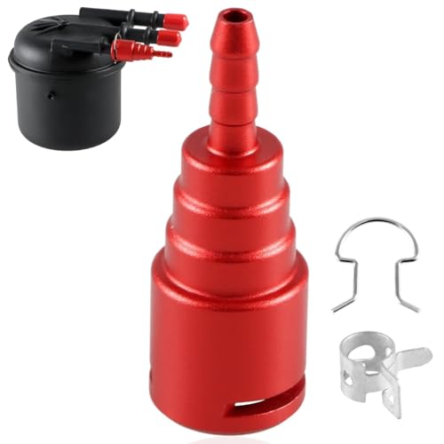
Servicing the 2005 F-150 fuel line plumbing requires specialized fuel line disconnect tools and strict safety protocols to prevent vapor flash-fires and contamination. When replacing line assemblies, you can consult our related procedures on Triton Fuel Rail and Injector Removal and our guide to Dropping the F-150 Fuel Tank.
Required Tools and Equipment


- 3/8-inch and 5/16-inch anodized aluminum Quick-Disconnect Fuel Line Tools (scissor or cylindrical barrel style)
- Safety glasses and nitrile gloves (fluoropolymer rated)
- Brass pick set (for removing internal seal garter springs without scratching sealing surfaces)
- Replacement fuel line safety retainers (duckbill style or secondary horseshoe latches)
- Class B (dry chemical/CO2) fire extinguisher
- Clean shop rags and a container to catch unrecoverable drain fuel
Step 1: Depressurize the Hydraulic System
Because the Electronic Returnless Fuel System maintains pressure in the supply tube long after engine shutdown, the system must be depressurized before releasing line fittings. Locate the passenger-side kick panel, open the access flap, and disconnect the electrical pigtail from the Inertia Fuel Shutoff Switch. Alternatively, remove the fuel pump fuse (Fuse 9, 20-amp, in the central junction box). Crank the engine for 10 to 15 seconds; the engine will start briefly, stall, and deplete the static rail pressure. Disconnect the negative terminal of the 12V battery before proceeding.
Step 2: Disengage Secondary Locking Retainers
Locate the connection point to be separated (such as the in-line fuel filter along the driver-side frame rail). Thoroughly spray the exterior of the fitting with brake cleaner or compressed air to remove loose rust, dirt, and road grit. The 2005 F-150 uses two styles of secondary retainers: a flip-up plastic cage or a slide-out duckbill clip. Using a small flathead screwdriver or trim tool, gently pry upward on the secondary locking collar until it unsnaps from the primary fitting body. If you break this clip, it must be replaced; do not run the line without secondary locks.
Step 3: Insert Quick-Disconnect Fuel Line Tool


Select the correct size Quick-Disconnect Fuel Line Tool (typically 5/16-inch for the filter inlet, 3/8-inch for the filter outlet and main rail inlet). Snap the tool around the rigid tube adjacent to the fitting. Firmly push the cylindrical collar of the tool straight into the open mouth of the female quick-connect housing. This inward motion spreads the internal spring-steel garter fingers away from the raised retention flare on the male tube.
Step 4: Separate the Joint and Inspect Internal O-Rings
While maintaining forward pressure on the disconnect tool to keep the garter spring expanded, pull the male line firmly out of the female coupling. A small residual quantity of gasoline will spill out; catch this with a shop rag. Look directly inside the female fitting housing using an inspection light. Every Ford quick-connect coupling houses two internal fluorocarbon (Viton) O-rings separated by a plastic spacer sleeve. If the O-rings are cracked, swollen, or missing, discard the line section or rebuild the fitting using an approved Ford quick-connect repair kit.
Step 5: Install the New Line Section
When routing a new pre-bent steel or braided replacement fuel line, thread it through the factory chassis mounts along the inside channel of the left-hand frame rail. Avoid placing the line in contact with bare metal edges or the steering shaft column. Lubricate the male tube end and the internal O-rings of the mating female fitting with a few drops of clean SAE 5W-20 engine oil or clean motor fuel. Never use silicone grease or petroleum jelly, which can degrade internal Viton seals or wash downstream into injector pintles.
Step 6: Lock Coupling and Verify Retention
Align the male tube squarely with the female fitting. Push the male line straight into the connector until an audible, mechanical “click” is felt and heard. Snap the secondary horseshoe locking clip or hinged safety cage completely over the connection. Once secured, perform a manual pull-test: grasp both sides of the fuel line joint and pull them firmly in opposite directions with roughly 25 to 30 pounds of force. The fitting must show zero axial slop or separation.
Step 7: Reconnect Electrics, Prime, and Pressure Check


Reinstall the fuel pump fuse or reconnect the Inertia Fuel Shutoff Switch. Reattach the negative battery terminal. Turn the ignition key to the ON position (KOEO) for three seconds, then turn it OFF. Repeat this key cycle three times. This activates the in-tank pump via the FPDM to prime the dry supply line and compress out trapped air pockets. Do not crank the starter until you have physically inspected every serviced fitting along the frame rail and fuel rail for signs of weeping or liquid leaks.
2005 Ford F150 Fuel Line Diagram Frequently Asked Questions
Where is the fuel filter located on a 2005 Ford F-150?
The in-line fuel filter is located along the inner channel of the driver-side frame rail, positioned roughly underneath the driver’s floor pan or the front edge of the cab door. It is protected by the frame rail flange and held inside a stamped metal clamp. The filter features a directional flow arrow stamped into its metal casing, which must point forward toward the front wheels and engine bay upon installation.
Why does my 2005 F-150 fuel rail lack a Schrader test valve?
Ford began phasing out the mechanical fuel rail Schrader test valve across modular engine platforms during the 2004 and 2005 model years. Because the Electronic Returnless Fuel System incorporates a high-accuracy Fuel Rail Pressure Transducer (FRPT) wired directly to the vehicle’s onboard diagnostics, Ford eliminated the mechanical port to reduce assembly costs and remove a potential evaporative leak source. Technicians must read fuel pressure via an OBD2 scan tool (PID: FRP) or install an inline mechanical gauge adapter at the fuel line disconnect fitting.
Can I patch a rusted 2005 F-150 fuel line with standard rubber hose?
No. You must never repair a 2005 Ford F-150 fuel supply line using standard low-pressure rubber vacuum hose, carburetor fuel lines, or screw-type worm clamps. The ERFS runs dynamic pressures peaking over 45 PSI, which will rapidly blow off standard hose clamps or rupture standard rubber lines. Repairs must be executed using rated SAE J2044 nylon fuel lines with heat-shrink unions, seamless steel tubing with 37-degree AN flare fittings, or OEM-style multi-layer braided lines designed explicitly for high-pressure electronic fuel injection.
How does the Fuel Pump Driver Module affect fuel line pressure?

The Fuel Pump Driver Module (FPDM) acts as the high-current electrical intermediary between the PCM and the in-tank fuel pump. Instead of providing continuous 12V power at a fixed rate, the FPDM rapidly pulses the ground circuit of the fuel pump based on digital command signals from the PCM. If the FPDM suffers internal corrosion or fractures, it fails to pulse the pump correctly, resulting in low line pressure, erratic fuel delivery, severe misfires under load, or a total fuel starvation condition.
What size quick-disconnect tool is needed for 2005 F-150 fuel lines?
Servicing the fuel delivery system on a 2005 F-150 requires both 5/16-inch and 3/8-inch fuel line disconnect tools. The main chassis fuel supply line connecting to the engine fuel rail and the outlet side of the fuel filter typically uses a 3/8-inch connector. The inlet side of the factory fuel filter and some auxiliary EVAP vapor connections utilize a 5/16-inch fitting. Having a complete set of spring-lock release collars ensures safe release of all chassis and fuel rail connections without damaging retention springs.
Step-by-Step Guide to Understanding the 2005 Ford F150 Fuel Line Diagram
Identify – Depressurize the fuel system by disconnecting the inertia switch behind the passenger kick panel and cranking the engine.
Locate – Find the primary 3/8-inch supply line running along the inside channel of the left-hand chassis frame rail.
Reference – Trace the fuel line routing diagram from the fuel sender outlet forward through the inline filter to the engine bay disconnect.
Connect/Route – Route replacement nylon or braided lines away from the exhaust manifold, securing them into the factory chassis retaining clips.
Verify – Cycle the ignition key to the run position three times to prime the system to 40 PSI without starting the engine.
Troubleshoot – Inspect all quick-connect collars for seeping fuel and scan for diagnostic codes P0190 or P0191 before test driving.