2000 Toyota Tundra Brake Line Diagram: Proper Routing 2026

The 2000 Toyota Tundra brake line system routes dual 3/16-inch steel lines from the master cylinder through the ABS actuator along the left frame rail. One circuit feeds front calipers via flexible hoses, while the secondary circuit routes rearward to the Load Sensing Proportioning Valve (LSPV) mounted above the rear axle assembly.
📌 Key Takeaways
- Master cylinder and ABS block ports utilize M10x1.0 inverted flare fittings with a 13 lb-ft (17 Nm) torque spec.
- The hydraulic system splits into an independent front split and a rear circuit regulated by a frame-mounted LSPV.
- Caliper bleeder screws must be torqued to an 8 lb-ft (11 Nm) torque spec to prevent shearing or stripped threads.
- Primary failure occurs via catastrophic rust perforation along the driver-side frame rail beneath the cab.
- Perform manual line replacement DIY, but seek professional service if ABS ECU solenoid cycling is required for bleeding.
Maintaining the hydraulic braking network on a first-generation Tundra requires an exact understanding of component layout, line transitions, and pressure circuits. The 2000 model year introduced Toyota’s full-size truck platform equipped with a front-disc and rear-drum configuration, managed through an anti-lock braking system (ABS) actuator and a chassis-mounted load-sensing proportioning valve (LSPV). Over decades of road operation, exposure to moisture, road de-icing salts, and cyclic pressure degradation leaves original steel brake lines vulnerable to catastrophic pinhole blowouts. Using an accurate 2000 toyota tundra brake line diagram allows technicians and experienced builders to trace hydraulic circuits, isolate pressure loss, perform precise flaring operations, and re-establish factory stopping performance.
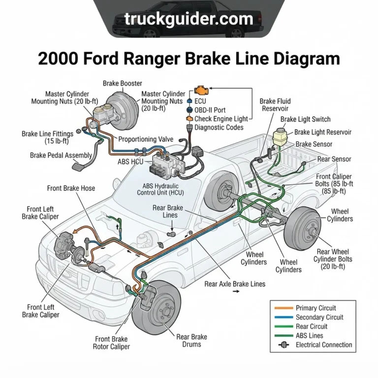
Schematic illustrating dual-reservoir master cylinder, inner-fender ABS actuator, front caliper rigid feeds, frame-rail intermediate hard line, rear Load Sensing Proportioning Valve (LSPV), and dual drum wheel cylinders.
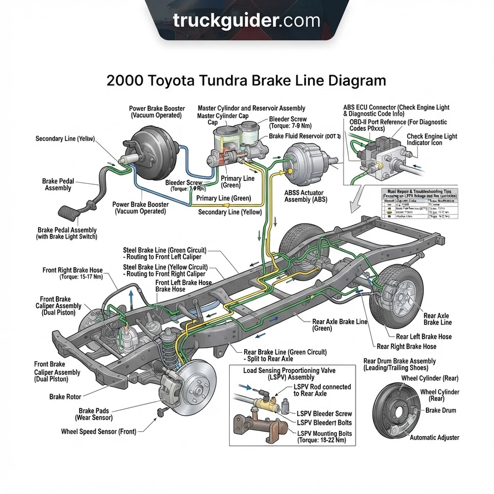
2000 Toyota Tundra Brake Line Diagram and Chassis Hydraulic Layout


The hydraulic circuit illustrated in the 2000 toyota tundra brake line diagram operates as an axially split, dual-circuit system engineered to maintain partial braking authority if one hydraulic channel experiences structural compromise. Hydraulic pressure begins at the tandem master cylinder assembly bolted directly to the vacuum brake booster on the driver-side firewall. The cast aluminum master cylinder uses a 1.0-inch internal piston bore with dual reservoirs: the primary chamber supplies pressure to the front disc calipers, while the secondary chamber manages fluid delivery toward the rear axle.
Two primary rigid lines exit the outboard face of the master cylinder body, routed downward along the inner fender sheet metal via M10x1.0 inverted-flare tube nuts into the ABS actuator and hydraulic control unit. In the 2000 model year, this compact assembly is mounted adjacent to the passenger-side or driver-side inner wheel house (depending on early versus late production sequencing and 2UZ-FE V8 versus 5VZ-FE V6 engine bay packaging). The hydraulic unit contains the motor-driven recirculation pump, high-pressure accumulator cavities, and normally open/normally closed solenoid valves. These electro-hydraulic solenoids are managed directly by the dedicated ABS ECU, which interfaces with wheel speed sensors and links to the vehicle powertrain monitoring network accessed via the cab’s OBD-II diagnostic connection.
From the ABS modulator block, three distinct output channels emerge:
- Left Front Brake Hard Line: Traces down the inner wheel well apron directly to a chassis-mounted junction bracket, where a reinforced flexible rubber hose bridges movement to the front four-piston fixed brake caliper.
- Right Front Brake Hard Line: Crosses the forward engine bay over the front suspension crossmember, closely following frame contours away from radiant thermal energy emitted by the exhaust manifolds and lower engine coolant flow pipes, terminating at the passenger-side wheelhouse bracket.
- Rear Axle Main Feed Line: Traverses downward toward the inside channel of the left-hand (driver-side) boxed frame rail. This long intermediate hard line shares structural retaining clips with the secondary fuel delivery and vapor return lines.
The single intermediate line travels rearward past the transmission crossmember and fuel tank enclosure until it reaches the chassis-to-axle transition point forward of the rear differential. Here, the hydraulic line terminates into the Load Sensing Proportioning Valve (LSPV) mounted to the rear frame crossmember. A secondary return/bypass line routes alongside the main feed, cycling proportioned pressure back toward the front circuit or differential housing depending on dynamic suspension compression. Flexible jumper hoses drop from the frame rail to the rear axle housing, feeding rigid steel lines that split left and right across the axle tubes into the rear drum wheel cylinders.
For trucks equipped with factory skid plates or off-road packages, the intermediate chassis hard line is shielded from rock strikes along the frame interior. Inspect the retention clips during regular chassis inspections, as trapped silt inside these plastic brackets accelerates localized pitting.
Torque Spec, Flare Profile, and Tubing Dimensions for 2000 Tundra Brake Lines


Fabricating or replacing hard lines according to the 2000 toyota tundra brake line diagram requires strict adherence to Japanese Industrial Standard (JIS) metric hardware conventions. Toyota did not use standard SAE 45-degree double flares or European DIN bubble flares on this chassis; the system relies on an inverted metric flare designed to seat against convex internal female ports at exact clamping forces.
Original OEM lines were manufactured from zinc-plated double-wall low-carbon steel (Bundy tube). When performing sectional or complete chassis replumbing, modern copper-nickel alloy tubing (NiCopp / C70600) is the preferred alternative. NiCopp meets SAE standard J1047 and ISO 4038 standards, providing 31,000 PSI burst pressure resistance while offering complete immunity to chloride-induced galvanic corrosion. Ensure that your flaring tool is configured specifically for inverted flares to avoid crushing the sealing cone inside the aluminum ABS modulator or LSPV cast body.
| Connection Location | Tubing Outer Diameter | Thread / Pitch | Flare Type | Torque Spec |
|---|---|---|---|---|
| Master Cylinder Outlet Ports | 3/16 in. (4.75 mm) | M10 x 1.0 | Metric Inverted (45°) | 15 N·m (11 lb-ft) |
| ABS Actuator Inlets / Outlets | 3/16 in. (4.75 mm) | M10 x 1.0 | Metric Inverted (45°) | 15 N·m (11 lb-ft) |
| Front Caliper Banjo Bolts | Flexible Hose Feed | M10 x 1.0 Banjo | Crush Washer / Flat | 30 N·m (22 lb-ft) |
| LSPV Body Fitting Ports | 3/16 in. (4.75 mm) | M10 x 1.0 | Metric Inverted (45°) | 15 N·m (11 lb-ft) |
| Rear Wheel Cylinder Inlets | 3/16 in. (4.75 mm) | M10 x 1.0 | Metric Inverted (45°) | 15 N·m (11 lb-ft) |
| Bleeder Screws (Caliper & Drum) | N/A | M7 x 1.0 / M8 x 1.25 | Tapered Cone Seat | 8.3 N·m (73 lb-in) |
| LSPV Manual Bleeder Screw | N/A | M7 x 1.0 | Tapered Cone Seat | 8.3 N·m (73 lb-in) |
Tube Nut Hex Size: Factory original M10x1.0 brake fittings feature a 10 mm hex head. Always utilize a high-quality 10 mm flare nut wrench (6-point line wrench) to torque or break loose these fittings. Standard 12-point open-end wrenches will round the soft leaded-steel hex flats.
Corrosion Hotspots on the 2000 Toyota Tundra Brake Line Diagram
The 2000 Tundra platform shares metallurgical exposure patterns associated with early first-generation Toyota truck chassis. Steel lines positioned along horizontal surfaces trap road brine, wet mud, and environmental debris, accelerating corrosion through chemical rust oxidation. When referencing your 2000 toyota tundra brake line diagram during an inspection, direct specific focus toward the following high-risk zones:
1. Driver-Side Frame Rail (Above the Fuel Tank): The intermediate rear hard line passes through a confined clearance pocket between the boxed frame channel and the primary fuel tank shield. Salt spray accumulates on top of the fuel tank flange, resting permanently against the steel line. Because this zone is invisible during casual under-vehicle inspections, severe line wall thinning occurs without outward symptoms until hydraulic rupture occurs during panic braking.
2. Load Sensing Proportioning Valve (LSPV) Junction: Bolted above the rear axle assembly, the LSPV contains multiple hydraulic ports, an adjusting spring arm, and a dedicated bleeder screw. Road turbulence throws moisture directly onto the valve body. Corrosion routinely seizes the bleeder valve and fuses the tube nuts into the cast housing, making non-destructive line removal impossible without intense localized induction heat.
3. Rear Axle Tube Spans: The rigid hard lines clipped to the trailing edge of the rear axle housing endure heavy abrasive blasting from road gravel thrown by the front tires. The zinc electroplating erodes rapidly, leaving bare steel exposed to road moisture.
Hydroscopic Fluid Degradation: Brake fluid formulated to DOT 3 specifications naturally absorbs moisture over time. Internal moisture settling in low pockets of the hydraulic circuit causes lines to rust from the inside out, masking structural failures that cannot be detected by external visual inspection alone.
Operational symptoms of line degradation manifest across several mechanical and hydraulic stages. A gradual loss of brake pedal firmness—where the pedal sinks slowly toward the floorboards while holding pressure at a stoplight—indicates micro-fissuring or severe bore seal leakage. If a hard line wall fractures, the pedal will instantly drop to the mechanical stop, the red BRAKE dashboard lamp illuminates, and reserve front braking drops significantly. Structural rubber flexible lines will exhibit external dry rot, deep checking, or internal layer separation; an internal collapse acts as a one-way check valve, holding caliper pressure after pedal release and generating severe brake drag, localized rotor glazing, and poor rolling efficiency.
Diagnosing Hydraulic Leaks Across the 2000 Toyota Tundra Brake Line Diagram
Locating a micro-leak or assessing pressure decay throughout the braking circuit demands a logical step-by-step diagnostic workflow before unbolting components. Complete this procedure systematically to evaluate both mechanical fluid retention and sensor-driven fault monitoring:
- Static Fluid Level and Master Cylinder Inspection: Clean the master cylinder cap and inspect the dual fluid level markings. If fluid sits below the minimum threshold, visually trace the primary and secondary firewall junctions. Pump the brake pedal 5 times with the ignition off until booster vacuum dissipates. Hold 100 lbs of foot pressure on the pedal for 45 seconds; any discernible drop confirms hydraulic fluid escape or internal master cylinder cup bypass.
- ABS Control System and OBD-II Data Interrogation: Connect a professional scan tool to the OBD-II diagnostic connector located under the lower driver dash panel. Query the ABS/VSC ECU for stored diagnostic trouble codes (such as C0210/C0215 for wheel speed anomalies or C1241 for low power/accumulator pressure faults). While a simple hydraulic leak rarely illuminates an engine check engine light directly, pressure drops causing asymmetric wheel lockup will trigger ABS-related diagnostic codes and disable stability functions.
- Mid-Chassis High-Pressure Line Profiling: Elevate the truck on frame jack stands. With an assistant applying firm pedal pressure, illuminate the driver-side frame rail inside face using an inspection light. Trace the brake hard line where it parallels the fuel delivery tubes and routing clips. Inspect for damp stains, fluid dripping from the frame weep holes, or bubbling line coatings indicative of pressurized fluid escaping under the plastic sleeve.
- LSPV Hydraulic Balancing and Linkage Evaluation: Inspect the LSPV adjusting spring anchored between the rear axle housing and the valve lever arm. Clean the valve body thoroughly using brake cleaner spray. Check the bleed screw nipple and the three flare junctions for seepage. Manually actuate the proportioning lever to verify internal spool valve movement; a frozen spool restricts fluid delivery to both rear drum assemblies, causing premature front lockup.
- Wheel Cylinder and Caliper Seal Verification: Inspect each front four-piston caliper casting around the piston dust boots and center crossover passage. Move to the rear drums, pull the inspection plugs on the lower backing plate, or remove the drums entirely. Pull back the rubber dust boots of the wheel cylinders with a small pocket screwdriver; any fluid presence inside the boot confirms internal cup seal failure, requiring cylinder replacement or hydraulic rebuilding.
Parallel routine inspections: just as you monitor timing chain condition, cooling system integrity, or engine oil pressure via dashboard instrumentation during preventive maintenance schedules, you must check hydraulic line condition at every oil change interval. While oil pressure sensors monitor internal hydrodynamic lubrication, hydraulic brake line decay is purely passive—making manual visual inspection the only reliable defense against pressure loss.
Fabrication and 5-Point Bleeding Procedures for 2000 Tundra Lines
Replacing failed hydraulic lines on the 2000 Tundra requires deliberate routing practices. When installing fresh 3/16-inch NiCopp tubing along the frame rail, bend the line carefully by hand or with tube bending mandrels to avoid flattening or kinking the tube radius. Maintain at least 2 inches of thermal clearance from the catalytic converters and exhaust pipe runs, and ensure the line does not chafe against sharp frame stamping edges. Reinstall the plastic chassis mounting isolators; if the original clips broke during removal, secure the lines using rubber-insulated stainless steel P-clamps bolted directly to factory frame drillings.
Once all hard lines, hoses, and flare fittings are seated to the required 15 N·m torque spec, complete the mandatory 5-point brake bleeding sequence. The inclusion of the chassis-mounted LSPV creates a hydraulic air pocket that cannot be cleared through standard wheel-end bleeding alone. Always utilize fresh, unconditioned DOT 3 brake fluid from a sealed container to ensure boiling point retention and seal compatibility.
Bleeding the 2000 Tundra out of sequence traps microscopic air bubbles inside the rear distribution circuit. The LSPV contains the highest fluid elevation point on the rear chassis circuit and must be addressed systematically according to the factory service manual protocol.
Execute fluid flushing through the following dedicated five-step bleeder sequence:
- Load Sensing Proportioning Valve (LSPV): Attach a clear vinyl hose to the bleeder screw on the rear proportioning valve body, submerging the other end in a catch bottle containing fresh fluid. Open the bleeder screw, have an assistant depress the pedal steadily, close the screw, and release. Repeat until fluid emerges completely free of air cavitation.
- Right Rear Drum Wheel Cylinder: Positioned furthest from the master cylinder along total hydraulic trace length, open this bleeder to sweep the long frame intermediate hard line and rear axle crossover feed.
- Left Rear Drum Wheel Cylinder: Bleed the driver-side axle hard line circuit, clearing the remaining air trapped downstream of the rear axle T-junction block.
- Right Front Disc Caliper: Bleed the caliper furthest from the master cylinder on the front circuit. On four-piston fixed calipers, clear both the inner and outer bleeder valves if aftermarket high-performance dual-bleed units are installed.
- Left Front Disc Caliper: Conclude the bleeding procedure on the driver-side front caliper, which possesses the shortest physical hard line connection from the master cylinder and ABS block.
If dry line installation allowed air into the internal ABS modulator cavities, a basic pedal bleed may yield an elastic pedal feel. Cycle the ABS pump motor solenoids utilizing an OBD-II diagnostic bidirectional scan tool, or perform several ABS-threshold stops on an unpaved gravel surface to force trapped air from the ABS valve pockets into the lines, followed by a final manual five-point system flush.
2000 Toyota Tundra Brake Line Diagram Diagnostic Code and Technical FAQs
Does a brake line failure trigger a check engine light or OBD-II diagnostic code?
A physical hydraulic rupture on a 2000 Tundra does not directly set a powertrain diagnostic code or illuminate the check engine light. The primary alert mechanism is the red dashboard BRAKE warning light, triggered mechanically by the low-fluid float switch inside the master cylinder reservoir. However, if asymmetric pressure loss induces radical wheel speed discrepancies while braking, the ABS ECU interprets this variation as an actuator or speed sensor fault. In such cases, the ABS light will illuminate and generate diagnostic trouble codes (DTCs) such as C0210 (Right Rear Speed Sensor Signal fault) or C1241 (Low Battery Positive Voltage or Pressure Imbalance), retrievable via an OBD-II port scanner.
Can I bend NiCopp brake lines by hand to match the 2000 Toyota Tundra brake line diagram?
Yes. 3/16-inch copper-nickel alloy (NiCopp) tubing is ductile enough to bend smooth, sweeping chassis contours by hand without work-hardening or pinching the internal diameter. However, when forming tight 90-degree transitions entering the ABS actuator ports, master cylinder fittings, or LSPV junctions, use a dedicated handheld tubing bender. Hand-bending tight radii risks collapsing the tubing profile, restricting fluid flow rates and compromising the hydraulic pressure rise time required during an ABS intervention event.
Why does my 2000 Tundra have five brake bleeder screws instead of four?
The fifth bleeder screw is integrated directly into the Load Sensing Proportioning Valve (LSPV) mounted on the crossmember above the rear axle. Because the LSPV sits physically higher than the rear axle housing and incorporates internal bypass channeling, air naturally rises and becomes trapped inside the valve body. If you bleed only the four wheel corners, this trapped air remains in the rear circuit, resulting in a low, spongy pedal regardless of how much fluid you pump through the caliper and wheel cylinder bleeders.
What is the correct replacement hardware standard for 2000 Tundra brake fittings?
All rigid brake hard line fittings on the 2000 Tundra use an M10x1.0 metric thread pitch with a 45-degree inverted (double) flare cone. Never install standard American 3/8-24 SAE fittings or European DIN bubble flares into these ports. Although an SAE 3/8-24 fitting will loosely start into an M10x1.0 female port, the thread pitch discrepancy (24 TPI versus roughly 25.4 TPI metric) strips aluminum threads under load and will fail catastrophically under normal line pressures exceeding 1,500 PSI.
Do I need to bypass the LSPV if I install an aftermarket suspension lift on my 2000 Tundra?
Bypassing the valve is dangerous because it sends full hydraulic pressure to the lightweight rear drum brakes under unladen conditions, causing violent rear-wheel lockup and fishtailing. When raising the suspension on a 2000 Tundra, you must adjust the LSPV sensing bracket attached to the rear axle. Install an LSPV bracket extension or manually adjust the threaded linkage rod so the valve lever remains in its neutral factory horizontal position at static ride height, preserving proper front-to-rear hydraulic brake bias balance.
Step-by-Step Guide to Understanding the 2000 Toyota Tundra Brake Line Diagram
Identify – Check the diagram to distinguish between front primary feeds and rear secondary brake circuits.
Locate – Find line termination points at the master cylinder, ABS module, and frame-mounted LSPV.
Reference – Trace the physical lines under the truck against the schematic to pinpoint corroded or damaged sections.
Connect/Route – Bend and route replacement lines along factory chassis clips, maintaining clearance from exhaust and suspension components.
Verify – Tighten all flare nuts to the factory torque spec and perform a multi-stage hydraulic fluid bleed.
Troubleshoot – Connect an OBD-II scanner to read any stored diagnostic code and verify no check engine light or ABS faults persist.