2005 Toyota Tacoma Parts Diagram: Component Breakdown (2026)

The 2005 Toyota Tacoma parts diagram maps major vehicle assemblies across the 4.0L 1GR-FE V6 and 2.7L 2TR-FE I4 platforms. It details component layout for the front double-wishbone suspension, A750E/F transmission linkage, and engine bay routing. Sub-assemblies link via standardized Toyota OEM reference callouts for precise maintenance and cross-referencing.
📌 Key Takeaways
- Front lower ball joint bolts require 59 ft-lb (80 Nm) torque with medium threadlocker.
- Frame structural layout distinguishes Access Cab and Double Cab wheelbase configurations (127.4″ vs 140.6″).
- 1GR-FE V6 oil filter relocation assembly utilizes an OEM O-ring (90301-88077) critical to preventing low-pressure leaks.
- Most common failure point on 2005 models is front wheel bearing hub assembly wear and intermediate steering shaft play.
- Replace bolt-on suspension and brake components via DIY; seek certified alignment or frame welding professionals for structural repairs.
The 2005 model year marked the launch of Toyota’s second-generation Tacoma, migrating the platform to a wider, fully boxed front subframe, an updated electrical architecture, and two completely redesigned engines: the 2.7L inline-four (2TR-FE) and the 4.0L V6 (1GR-FE). Navigating a factory 2005 Toyota Tacoma parts diagram requires understanding these generational platform shifts. Precise technical execution demands identifying exact part number variations between standard 5-lug utility variants, 6-lug PreRunner rear-wheel-drive configurations, and four-wheel-drive systems. Whether you are replacing front suspension uprights, servicing the secondary air injection system, or rebuilding differential assemblies, utilizing factory microfiche schematics ensures you isolate the exact Part Name Code (PNC) and superseded OEM part numbers specific to your vehicle identification number (VIN).
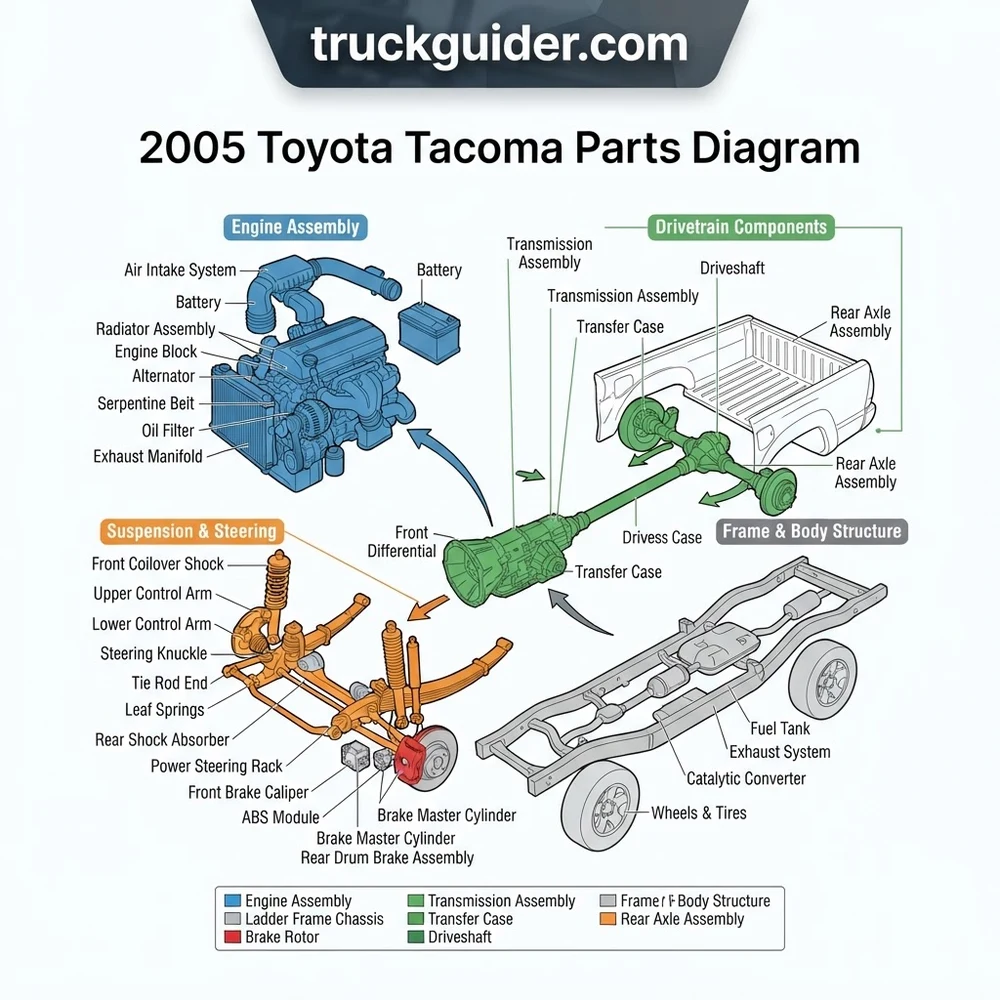
2005 Toyota Tacoma Parts Diagram: Core Chassis and Powertrain Layout


The structural layout of the 2005 Toyota Tacoma introduced distinct sub-chassis architectures that alter the schematic views across OEM service literature. The second-generation platform introduced high-strength steel reinforcements within the cabin structure and a hybrid hydroformed/stamped ladder frame. Powertrain blueprints dictate major variations in crossmember design, transmission tunnel geometry, and driveshaft carrier bearing positioning. For instance, the 2TR-FE 2.7L DOHC four-cylinder engine links to either the 5-speed manual (R155/R155F) or 4-speed automatic (A44D) transmission, while the 1GR-FE 4.0L V6 utilizes the 6-speed manual (RA60) or 5-speed automatic (A750E/A750F) transmission.



Selecting the correct diagram requires differentiating between the base 5-lug chassis and the elevated 6-lug platform. The 5-lug standard cab rides on a lower double-wishbone front suspension blueprint featuring an integrated coil-over configuration without the elevated spindle design of the 6-lug chassis. In contrast, the 6-lug PreRunner trim shares identical frame geometry, crossmembers, upper/lower control arms, and steering rack castings with the 4WD model, despite lacking a front transfer case and drive axles. Reviewing an exploded front axle schematic for a 2005 PreRunner shows an idle spindle hub blanking plate (OEM part number 43510-60011) where a 4WD model integrates a splined front drive hub assembly.
According to OEM specs, frame dimensional points and motor mount perches vary significantly by powertrain. The 1GR-FE requires offset frame brackets to clear the lower oil pan assembly and the dual-catalytic manifold exhaust routing. The table below details platform engineering baselines essential for cross-referencing your assembly schematics with physical chassis hardware:
| Platform Configuration | Engine & Drivetrain | Chassis & Lug Architecture | Front Suspension System | Rear Differential Type |
|---|---|---|---|---|
| Base Regular/Access Cab | 2.7L 2TR-FE / R155 (5-Spd MT) or A44D (4-Spd AT) | 5-Lug, 5×114.3mm PCD, Standard Ride Height | Double Wishbone, Low-Mount Ball Joint | Toyota 7.5-inch open carrier (3.308 / 3.583 ratio) |
| PreRunner (Access/Double Cab) | 2.7L 2TR-FE or 4.0L 1GR-FE / A750E (5-Spd AT) | 6-Lug, 6×139.7mm PCD, Raised Subframe | High-Mount Spindle, 4WD-pattern Wishbone | Toyota 8.0-inch or 8.4-inch (with opt. E-Locker) |
| 4WD (Access/Double Cab) | 4.0L 1GR-FE / RA60 (6-Spd MT) or A750F (5-Spd AT) | 6-Lug, 6×139.7mm PCD, 4×4 Drivetrain | High-Mount Spindle with CV Half-Shaft Pass-Through | Toyota 8.0-inch (8″ E-Locker) or 8.4-inch Open |
| X-Runner Sport Edition | 4.0L 1GR-FE / RA60 (6-Spd Close-Ratio MT) | 5-Lug, 5×114.3mm PCD, Lowered Frame | Double Wishbone with Firmer Dampers & X-Brace | Toyota 8.4-inch with mechanical limited-slip differential |
When reviewing technical layouts for wiring harnesses or fuel system components, consulting our companion guide on Tacoma electrical schematics helps locate fuse block junction positions (J/B No. 1 and J/B No. 2) under the instrument panel. Mechanical layouts dictate that four-wheel-drive transfer case electronic shift control actuators (OEM part number 36410-34015) map directly to cabin dash switches through dedicated sub-harnesses. Ensure that the frame model code stamped on the driver-side door jamb (e.g., GRN245 for a 4WD Double Cab V6, or TRN220 for a 2WD Regular Cab I4) matches the sub-header of the parts diagram page you consult.
Frame configurations on 2005 Tacomas utilize hydroformed front side rails transitioning to open C-channel sections under the truck bed. When referencing exploded frame schematics for structural repair or hitch receiver integration, always cross-reference the overall bed length code (B1 for 60.3-inch short bed vs. B2 for 73.5-inch long bed) to avoid misidentifying frame extension brackets and crossmember No. 4 positions.
Exploded Assembly Breakdown for 2005 Tacoma Mechanical Systems


Analyzing individual sub-assemblies within the 2005 Toyota Tacoma parts catalog requires parsing out exploded technical views. The factory parts catalog organizes components into four macro-groups: Engine/Fuel, Power Train/Chassis, Body, and Electrical. Within these groups, mechanical sub-systems are isolated into high-resolution line drawings showing every retaining clip, O-ring, fastener, and casting.



The front suspension and steering diagram for 6-lug models outlines the independent double-wishbone assembly. The upper control arm (PNC 48066/48067) anchors to the inner frame apron via a single long-shank through-bolt tightened to 115 Nm (85 ft-lbs). The lower control arm (PNC 48068/48069) mounts through dual eccentric cam alignment bolts (PNC 48190 and 48409) that permit independent camber and caster adjustment. These alignment cams must be torqued to precisely 135 Nm (100 ft-lbs). Connected to this wishbone structure is the power steering gear assembly (PNC 44200), which routes through the lower engine crossmember with high-pressure fluid lines entering from the vane pump assembly.
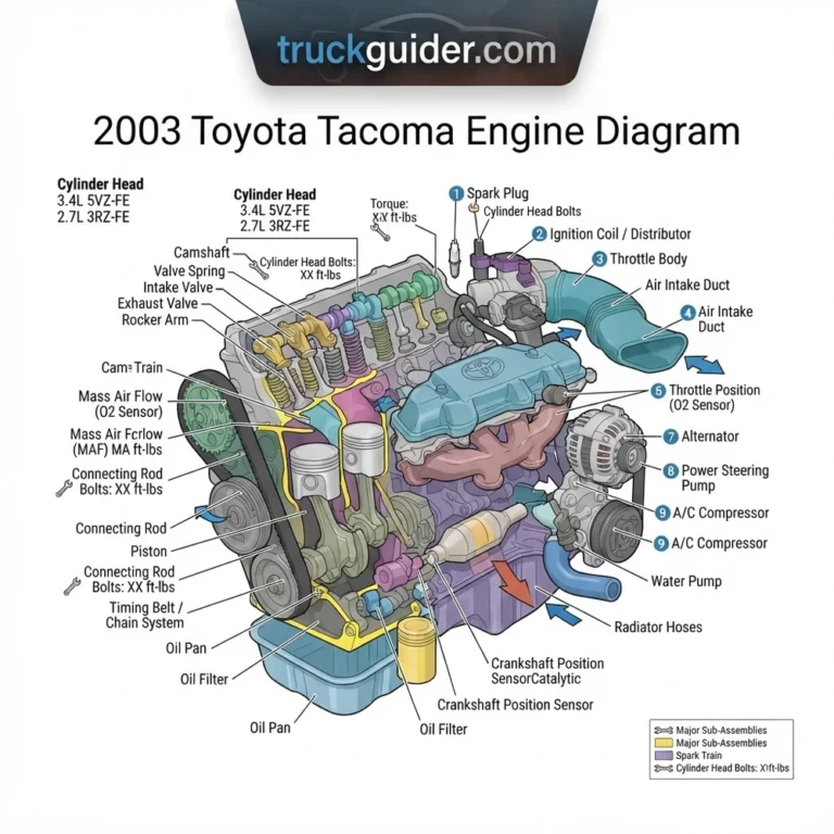
The engine mechanical and timing diagram for the 1GR-FE 4.0L V6 demonstrates an intricate timing chain blueprint. Unlike the belt-driven 5VZ-FE it replaced, the 1GR-FE uses three roller timing chains: one primary chain (PNC 13506, OEM part number 13506-31010) and two secondary chains driving the camshaft sprockets (PNC 13507). The diagram details the primary hydraulic chain tensioner (PNC 13540), tensioner slippers, and variable valve timing (VVT-i) oil control valves (PNC 15330/15340) threaded directly into the aluminum cylinder heads. Notice that the exploded view labels distinct O-rings on the water bypass pipe (PNC 16268) running through the engine valley beneath the intake manifold plenum.
| Mechanical Sub-Assembly | Key Component Callout (PNC) | Factory Part Number | Factory Fastener / Torque Spec |
|---|---|---|---|
| Front Suspension (6-Lug) | Lower Ball Joint Assembly (LH/RH) | 43330-09510 / 43340-09510 | Castle Nut: 140 Nm (103 ft-lbs); 4x Flange Bolts: 80 Nm (59 ft-lbs) |
| 1GR-FE Timing Assembly | Primary Timing Chain Tensioner | 13540-31011 | M6 Flange Bolts (2x): 10 Nm (89 in-lbs) |
| Chassis & Crossmember | Transmission Support Crossmember | 51203-04020 | Crossmember-to-Frame Bolts: 72 Nm (53 ft-lbs) |
| Rear Axle & Suspension | Leaf Spring U-Bolt Assembly (4x) | 90117-14023 | M14 U-Bolt Nuts: 100 Nm (74 ft-lbs) staggered |
| Driveline Assembly | Center Support Bearing (Carrier) | 37230-0K011 | Mounting Retaining Bolts: 40 Nm (30 ft-lbs) |
The chassis frame and crossmember diagram highlights the welded architecture supporting the cargo box and powertrain. Crossmember No. 2 spans between the front strut towers, serving as the front engine mounting perch. Crossmember No. 3 supports the rear transmission mount isolator (PNC 12371). If you are diagnosing driveline vibration issues, you should also review our structural guide on Toyota driveline carrier bearings to understand the dynamic relationship between the two-piece propeller shaft and frame crossmember No. 4.


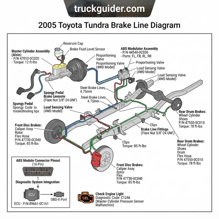
The rear axle and leaf spring suspension schematic illustrates the asymmetric shock absorber mounting layout (left shock positioned forward of the axle tube, right shock positioned behind it) designed to combat axle wrap under load. The rear leaf springs (PNC 48210/48220) anchor to the forward hanger via an 18mm bolt (OEM part number 90105-18006) torqued to 160 Nm (118 ft-lbs). The rear eyelet links to the shackle assembly (PNC 04483), secured with stepped lock nuts. Notice on the diagram that the load-sensing proportioning valve (LSPV) present on first-generation models was eliminated for 2005; brake fluid distribution is handled electronically through the ABS actuator and skid control ECU system located in the front right engine bay.
Rear leaf spring center pin alignment hole on the axle perch measures exactly 14.5mm. When reassembling from an exploded suspension diagram, ensure the downward protrusion of the center leaf spring bolt (OEM 90942-01007) seats fully inside this index hole before torquing U-bolt nuts to prevent axle tracking misalignments and severe dog-tracking conditions.
How to Read a 2005 Toyota Tacoma Parts Diagram Step by Step


Interpreting a 2005 Toyota Tacoma parts diagram requires transforming callout graphics into orderable 10-digit OEM part numbers. Toyota does not list fully formed part numbers directly on schematic illustrations. Instead, factory line art utilizes alphanumeric callout labels that correlate with an external database. Follow this sequential protocol to retrieve exact component matches using the Toyota Electronic Parts Catalog (EPC) or commercial OEM dealerships.
- Isolate the Vehicle Identification Number (VIN): Obtain the complete 17-digit VIN from the base of the driver-side windshield or the federal certification label on the B-pillar. Inputting the VIN into the EPC database automatically filters out invalid configurations (such as standard cab floor pans when viewing a Double Cab schematic) and isolates the exact engineering production date (MM/YY) of your truck.
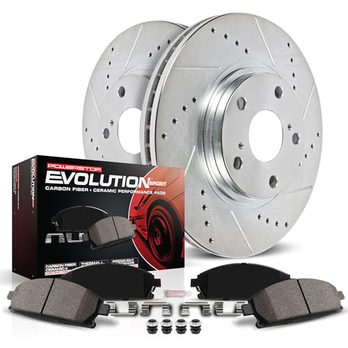
- Locate the Primary Component Group: Navigate through the primary master sections: Tool/Engine/Fuel (Section 1), Power Train/Chassis (Section 2), Body (Section 3), or Electrical (Section 4). For example, locating front brake pads requires navigating to Section 2: Power Train/Chassis > 47-05: Front Disc Brake Caliper & Pad.
- Identify the Part Name Code (PNC): Examine the exploded view schematic to find the graphical component you need. Toyota labels all components with a 5-digit or 6-digit Part Name Code (PNC). For instance, the front brake pad kit callout appears on the diagram not as a 10-digit part number, but simply as 04465. Hardware, such as anti-rattle spring clips, will feature distinct callouts like 04947.
- Cross-Reference the PNC to the Bill of Materials (BOM): Locate the PNC within the adjacent tabular bill of materials list. The catalog will match the callout “04465” to the exact 10-digit part number based on the vehicle attributes resolved in Step 1. For a 2005 6-lug Tacoma (4WD or PreRunner), the BOM resolves PNC 04465 to OEM part number 04465-04010 (subsequently superseded by 04465-AZ200).
- Analyze Schematic Hardware Callouts: If the diagram points to a bolt, washer, or nut, the label often begins with a “9” series callout code (e.g., 90119-14079). These are generic Toyota fastener codes. Unlike assembly components that use a PNC, 9-series codes are often the literal base part numbers, allowing you to source identical factory grade-8 or grade-10 JIS (Japanese Industrial Standard) bolts directly.
- Check Supersession and Revision History: Manufacturers continuously modify part designs. Within the catalog interface, select the specific 10-digit part number to display the supersession tree. Verify whether your 2005 component has been replaced by an updated part number incorporating engineering fixes for durability, fitment, or corrosion resistance.
When replacing structural suspension parts, consult our resource on Toyota fastener specifications to identify metric pitch classes (such as M12x1.25 fine pitch hardware vs standard M12x1.75 coarse hardware) designated across factory assembly blueprints.
Troubleshooting Diagram Mismatches and Common Ordering Errors


Visual ambiguities, platform overlap, and mid-cycle service campaigns can lead to ordering incorrect components from a 2005 Toyota Tacoma parts diagram. Avoid these common failure points when translating catalog schematics into physical components:


A frequent ordering error involves the front wheel hub and bearing assembly on 6-lug models. In factory diagrams, the exploded view of the front steering knuckle shows the wheel hub (PNC 43502), the front wheel bearing (PNC 43570), and the inner/outer oil seals (PNC 90316-69001 and 90312-96001). Technicians often assume the 2WD PreRunner utilizes a sealed, un-splined cartridge bearing different from the 4WD model. In reality, both the 2WD PreRunner and the 4WD Tacoma share the identical unitized front wheel bearing assembly (OEM part number 43570-04011). Ordering separate “2WD-only” wheel bearings from aftermarket catalogs typically yields parts suited only for the low-ride-height 5-lug chassis, which are incompatible with the PreRunner knuckle.
Do not rely on aftermarket repair manual diagrams (such as Haynes or Chilton) for precision fastener torque sequences or part identification on the 2005 Tacoma. Aftermarket manuals condense 5-lug, 6-lug, 2TR-FE, and 1GR-FE diagrams into generic composite line drawings, omitting vital model-specific oil seal orientations, brake rotor offsets, and exact wiring loom routing points.
Another major source of confusion stems from the comprehensive Toyota Frame Rust Recall Campaign (Customer Support Program / NHTSA Campaign ID: 16V-218). Under this campaign, hundreds of thousands of 2005–2010 Tacomas received entirely new service replacement frames supplied by Dana Holding Corporation. If your 2005 truck underwent a factory frame replacement, referencing the original 2005 chassis microfiche schematic may reveal structural discrepancies.
Replacement frames integrated updated rear leaf spring hanger gussets, altered catalytic converter heat shield mounting studs, and reinforced steering gear crossmember mounting bosses adopted from the 2011–2015 revisions. If your frame displays an authorized dealer campaign sticker or updated serialized plate on the right-hand frame rail, compare physical bracket patterns against 2010–2012 frame schematics before purchasing chassis-mounted hardware, brake hardlines, or fuel tank strap anchors.
Watch out for mid-year 2005 electrical and emissions updates. Early production 2005 1GR-FE models (produced between August 2004 and December 2004) feature a specific secondary air injection pump bracket and hose configuration (PNC 17610) that was modified for units produced after January 2005. Referencing the incorrect production split diagram results in purchasing air control tubes (PNC 25741) that will not clear the master brake cylinder booster assembly. Always cross-check the production month stamped on the driver-side door jamb decal before finalizing parts orders from emissions diagrams.
2005 Toyota Tacoma Parts Diagram Questions Answered
Where can I find an official 2005 Toyota Tacoma parts diagram for free?


You can access official factory schematics without a subscription through online Toyota dealership OEM parts portals (such as parts.toyota.com) or parts catalogs like Megazip and PartsSouq. These platforms license genuine Toyota Electronic Parts Catalog (EPC) vector graphics and exploded diagrams. Inputting your 17-digit VIN reveals exact factory assembly blueprints and Part Name Codes specific to your trim.
How do I differentiate between 5-lug and 6-lug parts diagrams?
Look for the hub and chassis callouts in the schematic header. 5-lug utility models are categorized under chassis codes TRN220 (2.7L) or GRN225 (4.0L X-Runner). The 6-lug platforms (PreRunner and 4WD) fall under TRN240/TRN245 (2.7L 2WD/4WD) or GRN245/GRN250 (4.0L 2WD/4WD). Furthermore, 5-lug diagrams clearly show 5 wheel studs on the front hub assembly (PNC 43511) and an under-slung rear axle layout, while 6-lug diagrams feature 6 studs and an over-slung rear leaf spring configuration.
What does a Part Name Code (PNC) mean on a Toyota schematic?
A Part Name Code (PNC) is an intermediate 5- or 6-digit category identifier used by Toyota to mark a component’s position within a schematic without tying the drawing to an individual part number. Because a component like an alternator bracket may use six different part numbers across various 2005 trims, the diagram uses a single universal PNC (e.g., 12511). The parts catalog database then cross-references this PNC against your specific VIN to provide the precise 10-digit part number required.
Why does my 2005 Tacoma 4.0L oil pan schematic show two separate sections?


The 1GR-FE 4.0L V6 utilizes a two-piece oil pan design. The upper oil pan assembly (PNC 12101) is a structural, thick aluminum casting that bolts directly to the engine block skirts to reinforce bottom-end rigidity and integrate the oil filter bypass passages. The lower oil pan (PNC 12102) is a simple stamped-steel fluid reservoir secured to the aluminum upper casting with 10 flange bolts and two retaining nuts. Diagrams label them as distinct sub-assemblies with unique liquid gasket application tracks.
Are 2005 Tacoma parts diagrams identical to 2006 and later years?
While the mechanical platform is largely consistent across the 2005–2015 generation, the 2005 model features several unique components not shared with later years. For instance, the 2005 1GR-FE motor utilizes an engine wiring harness and ECU protocol without standard tire pressure monitoring systems (TPMS) integration found in 2006+ revisions. Additionally, 2005 models feature unique front seat airbag occupant detection sensors and specific secondary air injection plumbing that Toyota revised in late 2006. Always verify your truck’s production split date when comparing diagrams across model years.
Step-by-Step Guide to Understanding the 2005 Toyota Tacoma Parts Diagram
Identify – Determine your specific vehicle configuration (engine type 2.7L vs 4.0L, cab style, and 2WD PreRunner vs 4WD system).
Locate – Find the target component assembly within the categorized structural layout sections of the parts schematic.
Reference – Match diagram callout numbers to the OEM part index to verify superseded part numbers and required quantities.
Connect/Route – Follow the exploded mechanical sequence to align brackets, route harnesses, and install hardware in proper order.
Verify – Check all installed components against factory torque specs, clearance tolerances, and fluid connection seals.
Troubleshoot – Inspect mounting points for misalignment or missing washers if vibration, binding, or fluid leaks occur post-assembly.