GM L87 6.2L Sensor Location Diagram: 2026 Complete Guide

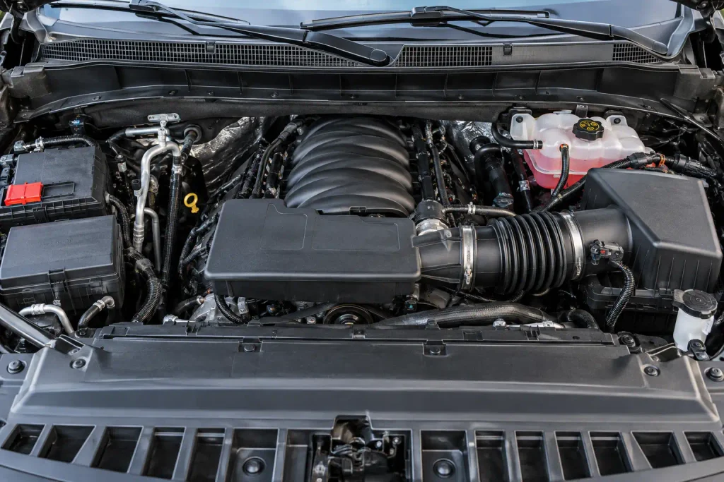
The L87 sensor location diagram is easiest to follow when you divide the GM 6.2L EcoTec3 V8 into four areas: the front timing-cover and water-pump area, the intake and fuel system on top, the left side near the oil filter, and the right rear near the starter. The oxygen sensors sit farther down the exhaust system.
On Chevrolet Silverado 1500 and GMC Sierra 1500 trucks, these landmarks help you locate a sensor without confusing it with a nearby solenoid, connector, or another engine’s component. Confirm your truck’s model year and engine code before touching a connector.
TruckGuider Technical Reference · GM 6.2L EcoTec3 V8
L87 Sensor Location Quick Map
Find each sensor by its GM component ID and a fixed engine landmark. This is a location index, not a scale drawing or a wiring diagram.
Front Center
Timing cover · water pump · intake
- B23Camshaft PositionTiming cover, above harmonic balancer
- B34Coolant TemperatureMounted at the water pump
- B74MAP SensorFront intake manifold, beside throttle body
Air Intake & Fuel Rail
Air-cleaner assembly · top rear
- B75Mass Airflow AssemblyAir-cleaner lid; also houses intake air sensing functions on documented L87 configurations
- B47BFuel Rail PressureRear of Bank 1 fuel rail; high-pressure system
Left Engine Side
Driver side · oil filter · manifold
- B37BEngine Oil PressureAbove oil filter, by oil-cooler-line area
- B68AKnock Sensor 1Left rear block, under exhaust manifold shield
Right Rear Engine
Passenger side · starter motor
- B26Crankshaft PositionRight rear block, behind starter
- B68BKnock Sensor 2Right rear block, above starter
Exhaust Oxygen Sensor Reference
Sensor 1 is upstream of its catalytic converter; Sensor 2 is downstream.
Bank 1
Bank 2
Which 2019 to 2026 GM Trucks Have the L87
The L87 is GM’s 6.2L EcoTec3 gasoline V8, introduced in the redesigned 2019 Chevrolet Silverado 1500 and GMC Sierra 1500. It is also used in certain later full-size GM SUVs. It is not the same engine as the 5.3L L84 or the earlier 6.2L L86.
| Engine code | Displacement | Why it matters for sensor location |
|---|---|---|
| L87 | 6.2L V8 | The engine covered by this locator |
| L84 | 5.3L V8 | Shares some GM service diagrams, but not every part or calibration |
| L86 | 6.2L V8 | Earlier engine; do not assume its diagrams match the L87 |
The GM L87 engine specifications identify its direct-injection and variable-valve-timing architecture. Chevrolet also lists the 6.2L EcoTec3 V8 among the 2026 Silverado 1500 engine options.
Check the eighth character of the VIN against your specific model-year owner’s manual. On a 2026 Silverado 1500, VIN engine code L identifies the L87. For an uncertain vehicle, a GM dealer can confirm the engine from the VIN.
If you are comparing the two modern GM gas V8s, the GM L84 5.3L engine specifications explain the related engine without treating it as identical to the L87.
How to Read the L87 Sensor Location Diagram
Start by facing the direction the truck travels. The front of the engine is toward the radiator and accessory belt; the rear is toward the transmission. Vehicle left is the driver’s side on a left-hand-drive U.S. truck, and vehicle right is the passenger side. A photograph taken from the front reverses how these sides appear to the viewer.
GM’s service information uses component identifiers such as B23 and B26. Use this quick location index before looking for the component in the engine bay.Area of the L87 Sensor and GM identifier Main physical landmark Front center Camshaft position sensor, B23 Timing cover, above the crankshaft balancer Front center Engine coolant temperature sensor, B34 Water pump Front intake Manifold absolute pressure sensor, B74 Intake manifold beside the throttle body Left front engine bay Mass airflow sensor, B75 Air-cleaner lid Top rear Fuel rail pressure sensor, B47B Rear of Bank 1 fuel rail Left engine side Engine oil pressure sensor, B37B Above oil filter, at oil-cooler-line area Left rear block Knock sensor 1, B68A Below exhaust manifold, behind shield Right rear block Crankshaft position sensor, B26 Behind starter motor Right rear block Knock sensor 2, B68B Above starter motor
These positions come from an L84/L87 service component location reference. It separates sensor identifiers and mounting descriptions from wiring diagrams.
Step 1 Find L87 Sensors at the Front
The front of the L87 contains three useful reference points: the harmonic balancer low on the engine, the timing cover above it, and the water pump in the cooling-system area. Look for those fixed components before searching for smaller connectors.
Camshaft Position Sensor B23
The B23 camshaft position sensor mounts at the front center of the engine on the timing-chain cover, above the left side of the crankshaft harmonic balancer.
With the engine off, identify the balancer and trace upward to the timing-cover area. Do not confuse the sensor with a variable-valve-timing actuator or another nearby electrical connection. Use the model-specific component view to confirm the connector before disconnecting anything.
Coolant Temperature Sensor B34
The B34 engine coolant temperature sensor is mounted at the water pump toward the front center of the engine. Find the water-pump housing and inspect the indicated sensor-mounting area using the factory locator.
A coolant-temperature reading on a scan tool identifies a measurement, not automatically a defective sensor. Never open a hot cooling system to investigate the sensor.
MAP Sensor B74
The B74 manifold absolute pressure sensor is mounted on the front-center intake manifold, to the left of the electronic throttle body as described by GM’s component locator. It measures intake-manifold pressure rather than airflow through the air-cleaner box.
Follow the intake duct to the throttle body, then inspect the manifold area beside it.
Step 2 Locate L87 Intake and Fuel Sensors
Trace the air path from the air-cleaner lid through the intake duct toward the throttle body, then identify the fuel rail at the rear of the engine.
Mass Airflow Sensor B75
The B75 mass airflow (MAF) sensor is installed at the air-cleaner lid in the left-front area of the engine compartment. It measures incoming air and provides information used by the engine control module.
Inspect the sensor housing and its electrical connector on the air-cleaner assembly. For additional identification guidance, see TruckGuider’s mass airflow sensor location guide.
Intake Air Temperature Functions
On the L87 configuration described in 2024 GM engine-control service information, the B75 MAF assembly also houses intake-air-temperature sensors, barometric-pressure sensors, and an intake-air-humidity sensor. That means a scan tool’s intake-air-temperature reading does not necessarily point to a separate sensor screwed into the intake tube.
The 2024 L87 engine-control diagnostic description describes these functions within B75.
Fuel Rail Pressure Sensor B47B
The B47B fuel rail pressure sensor is at the rear of the Bank 1 fuel rail on the engine. It is part of the high-pressure direct-injection system, not the low-pressure fuel-tank sensor.
Use the rear of the intake manifold and the Bank 1 rail as orientation references. Residual fuel pressure can be hazardous, even after the engine stops.
Step 3 Identify L87 Left Side Engine Sensors
On U.S. left-hand-drive trucks, this is the driver’s side. Look near the oil-filter and exhaust-manifold areas rather than searching the top of the intake manifold.
Engine Oil Pressure Sensor B37B
The B37B engine oil pressure sensor is on the left side of the L87 above the oil filter. The service locator describes it at the engine oil-cooler-line area near the left rear of the engine.
Find the oil filter and trace upward toward the mounting location.
The oil-pressure control solenoid is a separate component. A dashboard oil-pressure warning also needs a mechanical and diagnostic assessment rather than automatic sensor replacement.
Knock Sensor 1 B68A
The B68A knock sensor 1 mounts toward the left rear of the engine block, below the exhaust manifold and behind a knock-sensor shield. The exhaust manifold, shield, and block face are the important landmarks.
Do not reach into this area while the manifold is hot. A knock-sensor code may also involve the wiring or connector.
Step 4 Check L87 Right Rear Engine Sensors
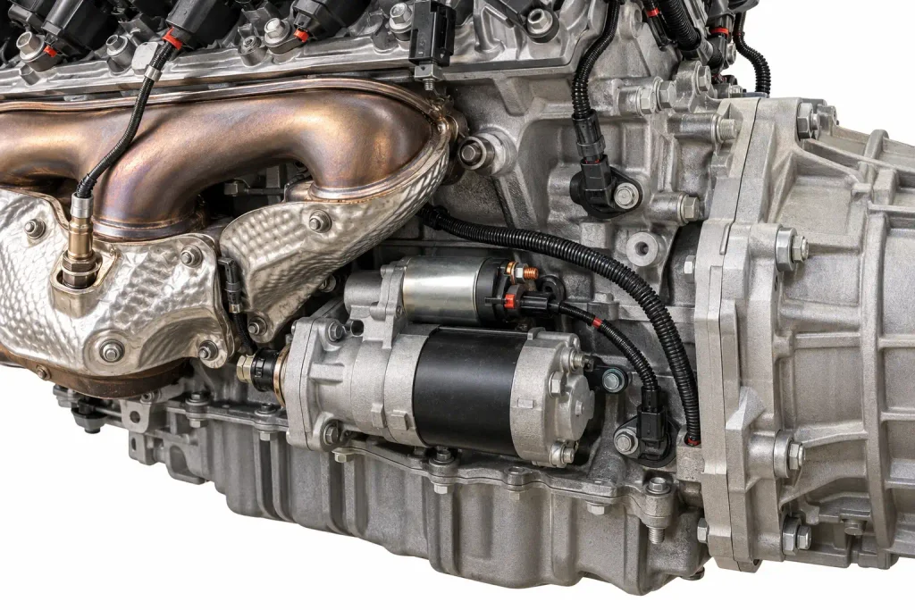
The starter motor is the key landmark on the right rear of the L87. Two separate sensors sit near this area, but their relative positions differ.
Crankshaft Position Sensor B26
The B26 crankshaft position sensor mounts at the right rear of the engine block behind the starter motor.
Locate the starter at the transmission end of the engine, then reference the block area behind it. The crankshaft sensor should not be mistaken for a starter terminal, ground connection, or transmission-mounted sensor. Removing the starter is not part of a basic visual inspection.
Knock Sensor 2 B68B
The B68B knock sensor 2 mounts on the right rear engine block above the starter motor.
When looking from underneath, identify the starter first, then use an inspection light to distinguish the two indicated mounting positions. Do not work underneath a truck supported only by a jack. Follow the exact GM removal procedure if access requires moving additional components.
Where Are the Four L87 Oxygen Sensors Located
Sensor 1 indicates the upstream position before a catalytic converter; Sensor 2 indicates the downstream position after it.
| GM identifier | Diagnostic position | Physical location |
|---|---|---|
| B52C | Bank 1 Sensor 1 | Bank 1 exhaust, upstream of catalytic converter |
| B52D | Bank 1 Sensor 2 | Bank 1 exhaust, downstream of catalytic converter |
| B52E | Bank 2 Sensor 1 | Bank 2 exhaust, upstream of catalytic converter |
| B52F | Bank 2 Sensor 2 | Bank 2 exhaust, downstream of catalytic converter |
Bank 1 is the cylinder bank containing cylinder 1, on the driver’s side of a typical U.S. Silverado or Sierra L87. Bank 2 is the passenger-side cylinder bank. Check the matching bank and exhaust routing in the truck’s service information before ordering an oxygen sensor.
A scan-tool reference to Bank 2 Sensor 2, for example, points to the downstream position on Bank 2, not the second sensor you happen to see beneath the truck.
How to Match L87 Sensor Codes to Locations
An OBD-II diagnostic trouble code (DTC) can identify the system or circuit needing attention. It does not, by itself, prove that the named sensor has failed.
- Read every stored and pending code. Record the exact code, freeze-frame information, and the conditions when the fault appeared. Avoid clearing evidence before diagnosing the concern.
- Identify the affected component or circuit. Check the DTC definition for your specific model year. A MAP-related fault, for example, directs attention toward the intake pressure measurement system, not automatically toward replacing B74.
- Locate the component. Use the identifier table and the appropriate front, top, left, right, or exhaust view. Make sure the wiring connector belongs to the named sensor.
- Check the circuit before replacing parts. Look for loose locks, corrosion, damaged insulation, and evidence of moisture. Use model-specific testing instructions for electrical measurements and repairs.
MAF-related diagnosis can also involve the intake-air-temperature functions housed in B75. TruckGuider’s intake air temperature sensor location guide explains why different engine designs use different arrangements; the L87 service documentation should determine which arrangement applies here.
If the truck runs poorly, stalls, overheats, or shows a persistent low-oil-pressure warning, do not rely on a location chart alone. Diagnose the underlying condition before continued operation.
What Changes Across 2019 to 2026 L87 Applications
The L87 was introduced for 2019 and remained an available 6.2L V8 in the 2026 Silverado 1500. This establishes the engine family covered here, not a guarantee that every sensor connector, harness route, bracket, or access procedure stayed unchanged.
The core location index uses L84/L87 service references, including 2024 Sierra information. A shared diagram label is useful for locating a component, but it is not a substitute for exact part fitment information.
A Tahoe, Yukon, Suburban, or Escalade equipped with an L87 may share sensor concepts without having the same engine-bay access as a Silverado or Sierra. Use the SUV’s own service manual for those applications.
How to Access L87 Sensors Without Damage
Finding a sensor is not the same as safely removing it. Start with the engine shut off, the parking brake set, and hot components allowed to cool. Use a flashlight or inspection camera before removing intake covers or reaching around the engine.
Identify the connector lock and release method in the service procedure, then inspect for bent terminals, broken retainers, oil contamination, or abrasion. Never probe a connector using a tool that could spread its terminals unless that method is specifically approved.
For sensors near the starter, exhaust, or underside, use appropriate vehicle support and electrical safety procedures. For fuel rail components, follow GM’s high-pressure fuel-system service instructions. Do not open pressurized fuel connections simply to confirm a sensor’s location.
How to Use the L87 Diagram Before Repairs
The L87 sensor location diagram is most useful when you first confirm the engine code, then match each GM sensor identifier to a fixed physical landmark. B23 is at the front timing cover, B75 is at the air-cleaner lid, B37B is above the oil filter, and B26 is behind the starter. These landmarks narrow the search without guessing from a photograph.
Before replacing any sensor, confirm the exact model-year layout and check the trouble code against the applicable diagnostic procedure. Inspect related wiring and connectors rather than assuming the sensor itself is defective. When access or testing involves high-pressure fuel, hot exhaust parts, or electrical circuits, follow the factory service information or use a qualified technician.
Frequently Asked Questions About L87 Sensor Locations
Where Is the L87 Crankshaft Position Sensor
The L87 crankshaft position sensor, B26, is mounted at the right rear of the engine block behind the starter motor. Use the starter as a landmark, but consult the matching service view before attempting to reach or remove the sensor.
Where Is the L87 Camshaft Position Sensor
The L87 camshaft position sensor, B23, is at the front center of the engine on the timing cover, above the left side of the harmonic balancer. Confirm the connector against the service diagram so you do not confuse it with nearby timing-control components.
Where Is the L87 Oil Pressure Sensor
The B37B oil pressure sensor is on the left side of the L87 above the engine oil filter, near the oil-cooler-line mounting area. It is a different component from the oil-pressure control solenoid, and a warning light alone does not establish sensor failure.
Does the L84 Have the Same Sensor Locations as L87
GM service documentation groups several sensor locator views under L84/L87, so some positions are shared. That does not mean every bracket, connector, calibration, or replacement part is interchangeable; verify the exact engine code, vehicle and model year.
How Can I Identify a Bad L87 Sensor
Start with trouble codes, freeze-frame data, a wiring and connector inspection, and the relevant live sensor readings. A faulty circuit, intake leak, cooling problem, or mechanical issue can create a sensor-related code even when the sensor itself still works.