2005 Ford F150 Exhaust System Diagram: 2026 Repair Guide

The 2005 Ford F-150 exhaust system layout features dual exhaust manifolds (5.4L/4.6L V8) feeding two warm-up and two downstream catalytic converters, converging into a single intermediate pipe (Y-pipe configuration). Gases pass through an oval center muffler and exit via a 2.5-inch tailpipe behind the passenger rear wheel, secured by rubber isolator hangers.
📌 Key Takeaways
- Exhaust manifold-to-cylinder head nuts require 9-10 lb-ft (12-14 Nm) torque in a specific cross-pattern
- Dual bank configuration uses four oxygen sensors (two upstream O2, two downstream catalyst monitors)
- Factory system transitions from dual 2-inch catalyst pipes into a single 2.5-inch intermediate pipe assembly
- Passenger-side exhaust manifold studs frequently corrode and snap, causing audible cold-start ticking
- Weld repairs or cat-back replacement are manageable DIY tasks; manifold stud extraction often requires professional tools
Navigating the exhaust architecture of the eleventh-generation F-150 requires a thorough understanding of factory pipe geometry, sensor locations, and emissions control packaging. The 2005 model year marked a pivotal era for Ford light-duty trucks, introducing fully integrated four-sensor emissions loops, hydroformed frame routings, and diverse wheelbase options across three distinct engine families: the 4.2L Essex V6, the 4.6L Triton 2V V8, and the 5.4L Triton 3V V8. This comprehensive reference and 2005 Ford F150 exhaust system diagram breaks down the operational blueprint of the entire exhaust path, from the cylinder head exhaust flanges down to the over-axle tailpipe exit.
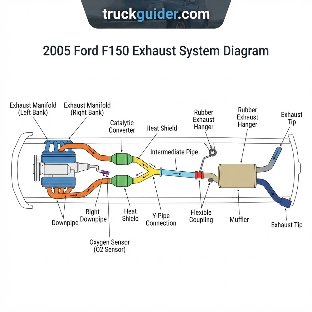
2005 Ford F150 Exhaust System Diagram: Component Breakdown & Specs


Analyzing the physical structure of the 2005 Ford F150 exhaust system schematic reveals a conventional single-side exit architecture downstream of a dual-inlet Y-pipe assembly. Factory plumbing utilizes aluminized 409 stainless steel tubing, balancing thermal dissipation with baseline corrosion protection. Every sub-assembly fulfills a calibrated thermodynamic and emissions role, governed by the Powertrain Control Module (PCM).



| Assembly Component | OEM Pipe OD / Spec | Mounting Location & Fasteners | Functional Overview |
|---|---|---|---|
| Exhaust Manifolds (Cast Iron) | Individual port to 2.00 in collector | Cylinder head faces; 8x M8x1.25 studs per bank | Channels post-combustion exhaust gases; thermal sink for early light-off |
| Upstream O2 Sensors (HEGO) | M18x1.5 threaded bung | Collector downpipes, 3 to 5 inches ahead of light-off cats | Provides short-term/long-term fuel trim feedback (STFT/LTFT) to PCM |
| Pre-Catalysts & Main Converters | 2.25 in OD dual downpipes | Tucked adjacent to transmission bellhousing / crossmember | 4-brick (or high-efficiency 2-brick) catalytic reduction of NOx, CO, and HC |
| Downstream O2 Sensors (CMS) | M18x1.5 threaded bung | Discharge side of secondary catalytic beds | Catalyst Monitor Sensors measure oxygen storage capacity to calculate catalytic efficiency |
| Y-Pipe Collector Flange | 2.50 in OD merged outlet | Transmission crossmember tail; 2-bolt slotted oval flange | Merges dual bank exhaust streams into single intermediate tract |
| Intermediate / Extension Pipe | 2.50 in OD (V6) / 2.75 in OD (V8) | Spans transmission slip yoke to forward muffler body | Compensates for wheelbase variations; establishes exhaust gas pulse velocity |
| Factory Muffler Assembly | 2.75 in ID inlet / 2.50 in ID outlet | Under rear cab/forward bed; dual rubber isolator rods | Triple-chamber reflection and absorption baffling to reduce NVH |
| Over-Axle Tailpipe | 2.50 in OD mandrel bent | Passes above right rear axle tube; passenger bedside hanger | Directs treated hot exhaust gases away from the rear tire and spare wheel well |
Exhaust Manifolds and Cylinder Head Interface


The cast-iron exhaust manifolds feature uneven-length primary runners merged into an integrated downpipe flange. On the Modular V8 platforms (4.6L and 5.4L), the passenger-side manifold geometry turns sharply inward toward the starter motor pocket, creating an intense localized heat envelope. OEM hardware consists of M8 x 1.25 carbon-steel studs threaded directly into aluminum cylinder head castings. Factory torque specifications mandate an inward-to-outward circular sequence to prevent casting warpage: tighten to an initial stage of 10 Nm (89 lb-in), followed by a final pass of 25 Nm (18 lb-ft). Multi-layer steel (MLS) gaskets seal the mating surfaces against dynamic combustion pressures up to 1,200 psi.
Heated Upstream and Downstream Oxygen Sensors (HEGO)
The 2005 F-150 management system incorporates four heated zirconia oxygen sensors operating on a 0.1 to 0.9-volt DC signal baseline. Upstream sensors (Bank 1 Sensor 1, Bank 2 Sensor 1) thread into bungs situated approximately 4 inches downstream of the exhaust manifold collectors. These sensors actively govern stoichiometric fuel management. Internal sensor heating elements operate at 12 volts supplied by the Battery Junction Box (BJB) fuse, drawing 1.2 to 2.1 amps with a nominal cold resistance of 3.2 to 5.0 ohms. Downstream sensors (Sensor 2 on both banks) monitor catalyst operational health by analyzing the residual oxygen dampening profile across the ceramic brick substrates.
Factory O2 sensor installation torque is strictly 40 to 50 Nm (30 to 37 lb-ft). Never coat sensor threads with copper anti-seize; rely exclusively on nickel-based, sensor-safe conductive lubricant to prevent catalytic poisoning and false high-voltage rich codes.
Y-Pipe Assembly with Integrated Catalytic Converters
The catalytic crossover configuration on the 2005 chassis relies on a dual-bank configuration that integrates four ceramic monoliths on early emissions packages, transitioning to a dual high-volume package on late 2005 production builds. Each leg measures 2.25 inches outer diameter (OD). The driver-side downpipe executes a deep sweep below the front driveshaft drop on four-wheel-drive models, passing directly below the 4R75E transmission pan. The two paths merge at a siamesed, stamped collector block, exiting through a 2-bolt diamond flange with a graphite-impregnated spherical donut gasket to absorb torsional frame flex during off-axis articulation.
Exhaust System Layout and Extension Pipe Configurations


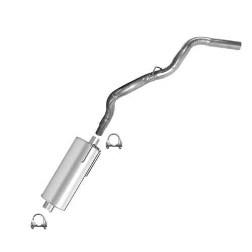

A primary source of confusion when interpreting a 2005 Ford F150 exhaust system diagram is the sheer variety of frame lengths. Because the F-150 utilizes three cab designs and three bed configurations, Ford established a standardized muffler and tailpipe position while using modular intermediate extension pipes to bridge the wheelbase delta. Mechanics must verify the chassis build code found on the B-pillar Safety Compliance Certification Label before ordering replacement piping.




| Cab Style | Bed Length | Wheelbase | Intermediate Pipe Type / Cut Length | Drivetrain Impact |
|---|---|---|---|---|
| Regular Cab | 6.5 ft Bed | 126.0 in | Direct Flange-to-Muffler (No extension) | Clear front driveshaft clearance |
| SuperCab | 5.5 ft Bed | 132.5 in | Short extension: ~14.0 in | Standard routing |
| SuperCrew | 5.5 ft Bed | 138.5 in | Mid extension: ~20.5 in | Requires heat shield near fuel tank |
| SuperCab | 6.5 ft Bed | 144.5 in | Long extension: ~30.0 in | Additional frame-mounted isolator |
| Regular Cab | 8.0 ft Bed | 144.5 in | Long extension: ~30.0 in | Direct hanger match with SuperCab 6.5′ |
| SuperCab | 8.0 ft Bed | 163.0 in | Extra-long dual-piece extension: ~48.5 in | Carrier bearing drop-bracket clearance required |
Wheelbase and Cab-to-Bed Intermediate Pipe Dimensions


The structural layout anchors the rear exhaust path to the transmission support frame crossmember via a heavy-duty vulcanized rubber bracket. On long-wheelbase variants (144.5-inch and 163.0-inch configurations), the intermediate pipe must navigate around the central two-piece driveshaft carrier bearing. If you are referencing our broader F-150 suspension lift kit exhaust clearance parameters, note that extreme driveline angles can force the rear slip-yoke boot into continuous contact with the front flange of the intermediate pipe unless the pipe hanger is re-indexed down by 0.75 inches.
Engine Variations: 4.2L V6 vs. 4.6L and 5.4L Modular V8s
Drivetrain selection directly alters the forward layout geometry:
- 4.2L Essex OHV V6: Employs cast log-style manifolds routed down to a 2.25-inch collector assembly. The Y-pipe downstream merge steps down to an economy-tuned 2.50-inch OD intermediate pipe. Upstream sensors use green-sleeved 4-pin square connectors mounted higher on the bulkhead.
- 4.6L Triton 2V V8: Employs conventional 2-valve heads with standard exhaust ports. The intermediate pipe measures 2.75 inches OD, providing a middle ground for low-end exhaust gas velocity and top-end volumetric flow.
- 5.4L Triton 3V V8: High-output 3-valve architecture with variable camshaft timing (VCT). This engine demands strict exhaust scavenging efficiency. The primary downpipes measure 2.25 inches, feeding through a low-restriction catalytic assembly into a full 2.75-inch (stepping up to 3.00-inch aftermarket) intermediate pipe. The downstream flanges feature an asymmetric bolt pattern to prevent improper Y-pipe indexing during production line assembly.
Intermediate extension pipes are directional. The slip-joint end contains an internal stop notch calibrated to slip 2.25 inches over the upstream Y-pipe lead-in. Failure to insert to the positive stop will distort overall hanger hanger alignment across the rear axle arch by up to 1.5 inches.
Troubleshooting 2005 Ford F150 Exhaust System Diagram Faults



Systemic failures within the 2005 exhaust footprint manifest as either mechanical structural breakdowns or computerized emissions sensor faults. Isolating the issue requires correlating real-time OBD-II live data with hands-on mechanical inspection.
Manifold Stud Shearing and Exhaust Leak Diagnostics
The most pervasive mechanical issue affecting the 2005 Ford F-150 involves the passenger-side (Bank 1) exhaust manifold hardware. Due to severe thermal cycling and lateral expansion mismatches between the cast-iron manifold and the aluminum cylinder head, the rear-most studs—specifically on cylinders 4 and 8—suffer from shear stress fatigue. The studs snap off flush with or below the cylinder head surface.


Diagnostic Symptoms:
- High-pitched rhythmic ticking or puffing sound during cold engine startup that diminishes after 3 to 5 minutes as thermal expansion closes the gap between the manifold flange and MLS gasket.
- Unmetered ambient air drawn into the manifold during negative pressure exhaust pulses, introducing excess oxygen directly across the upstream HEGO sensor.
- Diagnostic Trouble Codes (DTCs) P0171 (System Too Lean, Bank 1) or P0174 (System Too Lean, Bank 2) logged alongside elevated short-term fuel trims exceeding +18% at idle.
Do not attempt to extract broken M8 manifold studs with high-speed hand drills. The drill bit easily wanders from the carbon-steel stud into the soft aluminum cylinder head, irreparably damaging the water jacket. Always utilize a rigid stud extraction alignment jig plate with cobalt left-hand twist bits.
Catalytic Converter Efficiency and O2 Sensor Codes (P0420/P0430)
When the PCM illuminates the Check Engine light for P0420 (Catalyst System Efficiency Below Threshold – Bank 1) or P0430 (Bank 2), the downstream O2 sensor output voltage has mirrored the upstream sensor waveform, signaling that the washcoat substrate has lost its chemical oxygen-storage capacity. On the 5.4L 3V engine, this fault is frequently secondary to unburned fuel entering the exhaust stream from stuck-open fuel injectors (subject to Ford Customer Satisfaction Program 07M08) or erratic misfires detailed in our comprehensive Ford 5.4L Triton spark plug blowout repair guide.
To confirm catalytic failure versus a degraded downstream sensor:
- Connect an OBD-II scanner capable of live graphing to monitor Bank 1 Sensor 1 (B1S1) and Bank 1 Sensor 2 (B1S2).
- Bring the engine to full closed-loop operating temperature (ECT > 185°F / 85°C) and hold the engine speed at 2,000 RPM in Neutral.
- Observe B1S1 switching rapidly across 0.1V to 0.9V at approximately 1.5 to 2.5 cycles per second.
- Analyze B1S2: A functional converter displays a stable, flattened line between 0.55V and 0.75V. If B1S2 cycles synchronously with B1S1 (sine-wave pattern), the catalytic converter is spent and requires an integrated F-150 catalytic converter replacement.
- Inspect heater circuit continuity: Codes P0135, P0141, P0155, or P0161 indicate internal heating circuit open-loops. Disconnect the sensor harness and probe the two identical-colored heater wires; resistance must read between 3.0 and 8.0 ohms. An infinite (OL) reading confirms an open heater circuit within the sensor body.
Cat-Back Installation: 2005 Ford F-150 Exhaust System Schematic


Replacing the factory components from the intermediate pipe flange back with an aftermarket or OEM cat-back system restores exhaust velocity and clears road corrosion. Follow these sequential workshop steps to complete the installation safely and accurately.
-
Stage the Vehicle and Apply Penetrating Solvent:
Hoist the truck on a 2-post lift or position heavy-duty jack stands under the front frame rails and rear axle housing, achieving at least 24 inches of ground clearance. Liberally soak the two intermediate flange nuts, the slip-joint sleeve clamp, and all rubber hanger prongs with a dedicated rust penetrant. Allow a minimum dwell time of 20 minutes. -
Decouple the Intermediate Y-Pipe Connection:
Using an impact wrench with a 15mm deep socket and a long universal extension, extract the two M10x1.5 flange nuts securing the intermediate extension pipe to the catalytic Y-pipe collector flange. Inspect the OEM pressed studs. If the threads show severe rust pitting, drive the studs out using an air hammer with a blunt punch tool, replacing them with Grade 10.9 M10x1.5x45mm bolts and prevailing-torque locknuts. -
Extract the Tailpipe and Muffler Assembly:
Support the central muffler body with a transmission jack. Unbolt the rear-most factory 2.5-inch band clamp positioned over the rear axle arch. Disengage the steel hanger rods from their vulcanized rubber isolators using exhaust hanger removal pliers. Slide the tailpipe rearward over the axle housing, rotating the plumbing 45 degrees downward to navigate between the rear leaf spring pack and the spare tire heat shield. Once the tailpipe clears, drop the muffler and intermediate pipe from the chassis. -
Hang the New Intermediate and Extension Pipe:
Offer the replacement intermediate pipe up to the catalytic Y-pipe flange. Insert a new high-temperature composite or graphite spherical donut gasket into the female flange bevel. Hand-tighten the M10 fasteners so the joint can pivot slightly during downline alignment. For extended wheelbase models, slide the secondary extension pipe over the intermediate pipe to the internal depth mark (minimum 2.25 inches overlap). -
Mount the Replacement Center Muffler:
Lubricate the frame isolators with silicone paste (never use petroleum grease, which degrades EPDM rubber). Slide the front and rear muffler bracket prongs into the rubber chassis mounts. Join the muffler inlet neck over the intermediate extension pipe. Position a 360-degree reaction-block band clamp or U-bolt clamp over the slip joint. Hand-snug the hardware to allow rotational adjustments. -
Route the Over-Axle Tailpipe Section:
Snake the over-axle tailpipe pipe over the rear differential tube, entering from the rear bumper side. Ensure a minimum of 1.25 inches of radial clearance around the rubber rear brake flex lines, ABS wheel speed sensor cabling, and the right rear shock absorber cylinder. Push the tailpipe front inlet into the muffler outlet neck. Engage the rear-most hanger rod into the bedside frame isolator. -
Execute Final Torque Sequence and Alignment Sweep:
Systematically adjust pipe rotation to ensure absolute clearance along the length of the frame. Torque the primary Y-pipe flange bolts to 47 Nm (35 lb-ft). Working progressively from front to rear, torque all 2.5-inch and 2.75-inch exhaust band clamps to 61 Nm (45 lb-ft). If traditional stamped U-bolt saddle clamps are utilized, torque nuts evenly to 47 Nm (35 lb-ft). -
Thermal Cycling and Leak Verification:
Start the engine and run at idle. Coat all flanged connections, slip-joints, and sensor bungs with a soapy water solution to inspect for foaming bubbles, which indicate exhaust leaks. Once confirmed leak-free, conduct a 15-minute operational road test to bring the exhaust up to operating temperatures. Let the vehicle cool down completely, then re-torque the intermediate flange bolts and slip clamps to compensate for the initial thermal relaxation of the fasteners.
2005 Ford F150 Exhaust System Diagram FAQs
What is the stock exhaust pipe diameter on a 2005 Ford F-150?
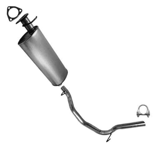

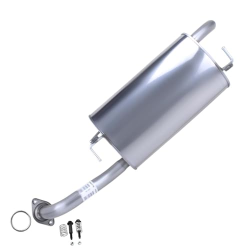
On the 4.6L and 5.4L Modular V8 configurations, the factory exhaust system relies on dual 2.25-inch OD downpipes exiting the catalytic converters, merging into a single 2.5-inch collector. The intermediate extension pipe steps up to 2.75 inches OD feeding into the inlet of the central muffler. Downstream of the muffler, the single over-axle tailpipe steps down to 2.50 inches OD through its exit behind the passenger rear wheel. The 4.2L Essex V6 variants employ a 2.50-inch OD pipe architecture continuously from the primary collector to the tailpipe tip.
Can I delete the pre-catalytic converters without setting a Check Engine light?
No. The 2005 F-150 emissions control software continuously evaluates catalyst conversion efficiency via the downstream oxygen sensors. Removing the forward light-off catalysts eliminates the rapid thermal burn required to oxidize emissions during the open-loop warmup phase. This structural removal causes the downstream sensors to swing erratically, immediately logging DTCs P0420 and P0430. Furthermore, tampering with factory emissions configurations violates Federal EPA clean air standards under Section 203(a)(3) of the Clean Air Act.


Why does my 5.4L F-150 tick loudly only on cold starts?
A cold-start tick that fades as the engine warms is the hallmark signature of a cracked exhaust manifold or sheared exhaust manifold studs, almost exclusively localized to the rear cylinders (cylinders 4 and 8) on the passenger-side cylinder head. The cast-iron manifold shrinks when cold, exposing a leak path through the fractured steel gasket. As the engine runs, thermal conduction expands the manifold casting, pressing it back against the cylinder head face and temporarily sealing the gap until the next complete cooldown cycle.
How do I wire an aftermarket universal O2 sensor into the 2005 F-150 harness?
OEM Ford harness pigtails typically utilize a 4-wire color code: two white wires for the internal heater circuit, one black wire for sensor signal return (ground), and one gray or blue wire for the positive sensor signal input (0.1–0.9V to the PCM). When interfacing with a universal sensor, verify heater continuity with a digital multimeter first. Heater circuits have no polarity sensitivity, but signal lines must correlate directly: wire the replacement sensor signal positive to the vehicle harness signal line and signal negative to the PCM ground reference. Always solder connections and seal with dual-wall adhesive heat shrink to prevent moisture intrusion.
What are the torque specifications for the 2005 F-150 exhaust manifold to downpipe flange?


The two-bolt flanged downpipe connection linking the exhaust manifold collector to the Y-pipe uses M10 x 1.5 studs with flanged locking nuts. Tighten these fasteners evenly in alternating passes to an absolute factory specification of 40 to 47 Nm (30 to 35 lb-ft). Exceeding this torque threshold risks stripping the internal threads out of the cast-iron manifold collector flange or snapping the pressed mounting studs.
Step-by-Step Guide to Understanding the 2005 Ford F150 Exhaust System Diagram
Identify – Match your engine size (4.2L V6, 4.6L V8, or 5.4L V8) and wheelbase configuration to the corresponding diagram schematic.
Locate – Find the specific exhaust component requiring service, noting upstream/downstream oxygen sensor locations and frame hanger mounts.
Reference – Cross-reference flange connection points, gasket part numbers, and factory torque specifications shown in the diagram legend.
Connect/Route – Align replacement pipes and mufflers into the OEM rubber isolator hangers, ensuring minimum 1-inch clearance from brake and fuel lines.
Verify – Torque all flange hardware progressively to specification (25-35 lb-ft for exhaust flanges) and start the engine to check for audible leaks.
Troubleshoot – Inspect joint sealing with soapy water if ticking or hissing persists, and scan OBD-II data to confirm functional O2 sensor voltage switching.