2002 Ford F150 Parts Diagram: Component Breakdown (2026)

A 2002 Ford F150 parts diagram maps the 10th-generation PN-96 architecture, detailing Triton 4.6L/5.4L engine assemblies, 4R70W/4R100 transmissions, and SLA front suspension geometry. It indexes OEM callout numbers, fastener torque ratings, and sub-assembly layouts essential for isolating damaged components and ensuring precise factory reassembly.
📌 Key Takeaways
- Covers 10th-gen platform specs including Triton 4.6L (W) and 5.4L (L/Z) modular V8 configurations.
- Uses Ford 4-to-5 digit base part numbering (e.g., 6049 for cylinder heads, 3078 for control arms).
- Critical spark plug torque spec is 11–14 lb-ft (15–19 Nm) into aluminum heads to prevent blowout.
- Most common failure points include intake manifold coolant crossover cracks and DPFE sensor faults.
- Simple bolt-on repairs suit DIYers, but internal 4R70W transmission rebuilds require shop presses and gauges.
Executing repairs, overhauls, and preventative maintenance on the tenth-generation (PN-96 platform) Ford F-Series requires an exact technical understanding of factory engineering schematics. Navigating a 2002 ford f150 parts diagram demands more than simply matching visual shapes; it requires interpreting Ford’s functional numbering system, differentiating between powertrain-dependent sub-assemblies, and accounting for mid-cycle platform revisions. With configurations spanning standard rear-wheel drive (4×2) coil setups, four-wheel drive (4×4) torsion bar systems, three cab variations (Standard, SuperCab, and SuperCrew), and three primary engine architectures (4.2L Essex V6, 4.6L Triton V8, and 5.4L Triton V8), selecting the correct replacement component hinges on structural schematics. This guide breaks down the chassis, powertrain, suspension, and hydraulic layouts of the 2002 Ford F-150, providing certified technicians and experienced builders with the factory callouts, torque limits, and schematic structures necessary to execute precision repairs.
[DIAGRAM_PLACEHOLDER: Exploded View of 2002 Ford F-150 Chassis, Powertrain, and Running Gear Layout]
Full assembly blueprint highlighting front SLA suspension, modular 2V Triton powertrain, 4R70W/4R100 transmission cross-members, and 8.8/9.75 rear axle differential groups.
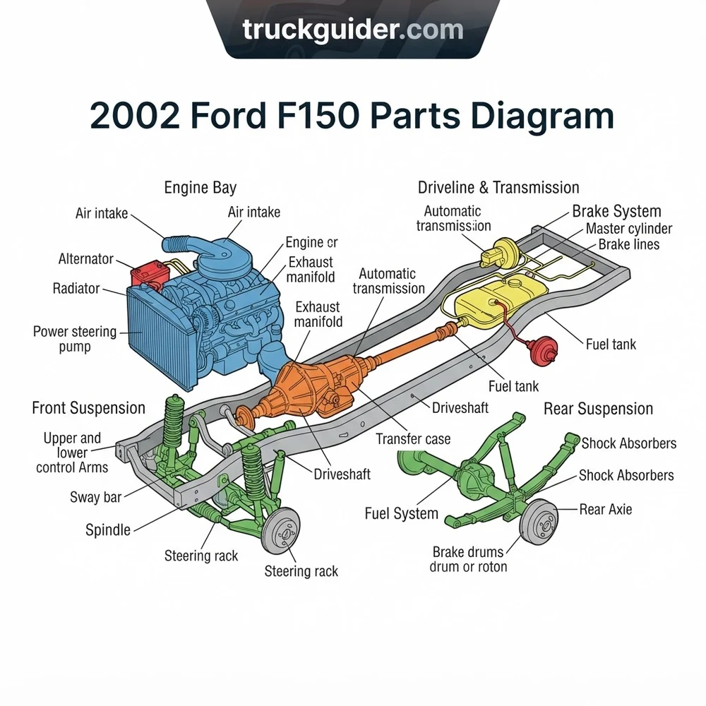
2002 Ford F150 Parts Diagram: Complete Chassis and Suspension Layout


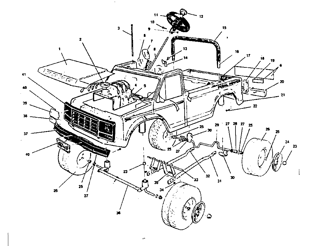
The underbody structure of the 2002 Ford F-150 utilizes an unequal-length short-and-long arm (SLA) independent front suspension paired with a traditional Hotchkiss live rear axle suspended by multi-leaf steel springs. Schematic interpretation requires immediately identifying the drive configuration: 4×2 variants utilize front coil springs seated in a stamped steel lower control arm pocket, whereas 4×4 variants rely on longitudinal torsion bars anchored to a dedicated intermediate cross-member with adjustable key plates.
Front Suspension Assembly and Torsion Bar Configuration

In 4×4 configurations, the front schematic isolates the upper control arm (base part number 3084 right-hand, 3085 left-hand) featuring integrated ball joints and bonded rubber bushings. The forged steel lower control arm (base 3078/3079) carries the primary torsion bar receiver socket. OEM specifications dictate that torsion bars (base 5B326/5B327) are directional; swapping left-to-right causes structural fatigue and ride height settling. When viewing the exploded suspension layout, the torsion bar cross-member insulator mounts (base 5330) and adjustment bolts (base 3B282) establish the baseline ride height, or “Z-height,” which controls the working geometry of the constant-velocity (CV) half-shafts on four-wheel-drive configurations.
Steering Linkage, Idler Arm, and Gearbox Overview
The steering schematic details a recirculating-ball steering gearbox (base 3504) linked to a structural parallelogram layout. The pitman arm (base 3590) mounts directly to the sector shaft, engaging the center link (drag link, base 3304). The passenger-side pivot is anchored by the frame-mounted idler arm assembly (base 3350). Both inner and outer tie rod ends (base 3A130 and 3A131) interface via threaded adjustment sleeves (base 3281). Technicians must reference the fastener torque specifications in the diagram footnotes: the pitman arm-to-sector shaft nut demands 230–285 Nm (170–210 lb-ft), while idler arm-to-frame mounting bolts require 160–215 Nm (118–159 lb-ft).
Rear Axle and Leaf Spring Suspension Structure
The rear running gear schematic centers on the leaf spring assemblies (base 5560) secured to the rear axle housing via four heavy-duty U-bolts (base 5455) and an underlying anchor plate (base 5798). For the 2002 model year, Ford utilized staggered rear shock absorbers—one positioned forward of the axle tube and one rearward—to counteract dynamic axle wrap under load. The spring eyelet bushings utilize bonded rubber sleeves that mount through forward frame brackets (base 5775) and rearward pivoting shackles (base 5630). Fasteners must remain untorqued until the suspension is compressed to curb weight to prevent torsional bushing bind.
Brake System Hydraulics and ABS Module Layout
Braking schematics for the 2002 model year depict a four-wheel disc brake layout across all trim packages. The hydraulic circuit splits from the vacuum booster-assisted master cylinder (base 2140) into the 4-wheel Anti-Lock Brake System (4WABS) Hydraulic Control Unit (HCU, base 2C215) and integrated electronic control module (base 2C346). Front caliper brackets (base 2B135) house dual-piston phenolic calipers (base 2B120/2B121), while the rear employs single-piston calipers (base 2552/2553) with an integrated internal drum-in-hat mechanical parking brake assembly (base 2648).
| Assembly Callout | OEM Base Number | Torque / Spec Rating | System Function & Configuration |
|---|---|---|---|
| Upper Control Arm & Ball Joint | 3084 (RH) / 3085 (LH) | 113–153 Nm (83–113 lb-ft) | Maintains front camber/caster; integral sealed ball joint |
| Lower Ball Joint Assembly | 3050 | 113–148 Nm (83–109 lb-ft) | Press-fit structural load carrier in lower control arm |
| Steering Idler Arm Support | 3350 | 160–215 Nm (118–159 lb-ft) | Frame-mounted steering drag link pivot pivot bracket |
| Rear Spring U-Bolt Nuts | 5455 (U-bolt) / N800 | 102–142 Nm (75–105 lb-ft) | Cross-pattern torque; clamps spring pack to axle tube |
| Front Hub & Wheel Bearing Assembly | 1104 (4WD) / 1102 (2WD) | 295 Nm (218 lb-ft) | Non-serviceable cartridge hub; center spindle nut rating |
According to OEM chassis specs, front wheel spindle nuts (callout 3B477) on 4×4 models use a single-use torque-to-yield design requiring 295 Nm (218 lb-ft) of torque. Never reuse a removed spindle nut; doing so compromises preload on the unitized front hub assembly, leading to premature bearing failure and potential ABS sensor air-gap misalignment.
Engine and Drivetrain Blueprint: 2V Triton V8 and Transmission Systems


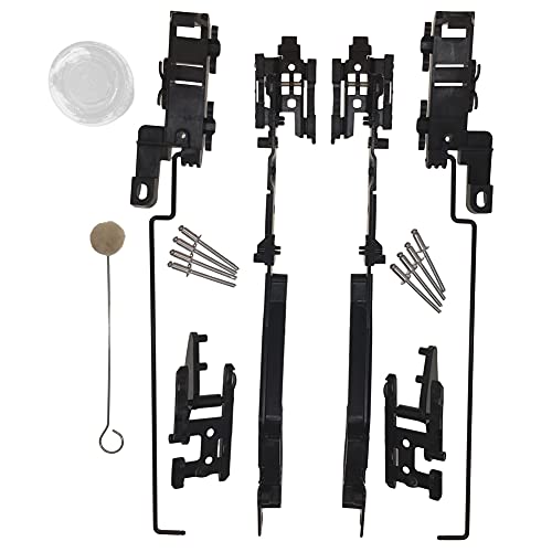
The powertrain schematics for the 2002 model year showcase the mature architecture of Ford’s 2-Valve Modular engine platform. While the 4.2L Essex V6 remained base equipment, the primary light-truck platforms relied on the 4.6L (VIN W or VIN 6) and the 5.4L (VIN L) 2V SOHC Triton V8 engines. Understanding the structural exploded views requires navigating distinct oiling paths, cylinder head casting changes, and secondary sensor placement across Romeo and Windsor engine plants.
4.6L and 5.4L 2-Valve Triton V8 Powertrain Architecture
The exploded engine blueprint breaks down the deep-skirt cast-iron engine block (base 6010) topped with aluminum cylinder heads (base 6049 RH, 6050 LH). The primary timing group includes two single-row timing chains (base 6268), hydraulic tensioners (base 6L266), fixed chain guides (base 6K255), and swinging tensioner arms (base 6K297). SOHC 2V models route oil through restrictor orifices in the head gasket to the overhead camshafts (base 6250). Camshaft endplay and gear alignment rely on a keyway drive interface with the crankshaft timing sprocket (base 6306). When referencing the engine cooling circuit, note that the water pump (base 8501) discharges directly into the engine block cavity, with system coolant returned via an aluminum crossover pipe integrated into the intake manifold assembly (base 9424).
Ignition Coil-on-Plug (COP) and Fuel Delivery Circuits
For the 2002 model year, all Triton V8 platforms use an individual Coil-on-Plug (COP) ignition architecture (base 12A366), discarding the earlier paired EDIS coil packs. The primary ignition wiring relies on specific color codes: each coil shares a common Red/Light Green switched 12V feed from the powertrain power relay, while individual signal-return ground circuits route directly to the Powertrain Control Module (PCM, base 12A650) to trigger saturation and discharge. The fuel rail blueprint (base 9F792) depicts a returnless or semi-return mechanical manifold holding eight top-feed injectors (base 9F593). Pressure is monitored via a manifold-referenced Fuel Rail Pressure Sensor (FRPS) or regulated mechanically through vacuum balance, sustaining system pressure between 270 and 310 kPa (39–45 PSI).
Early 2002 Triton 2V cylinder heads (Performance Improved ‘PI’ design) feature only 4 to 5 threads within the spark plug wells (base 12405). Manufacturer specs dictate spark plug tightening strictly to 15–19 Nm (11–14 lb-ft). Under-torquing leads to harmonic blowouts, while over-torquing strips the soft aluminum threads. Always verify thread insert requirements before securing plugs.
Transmission and Transfer Case Configuration (4R70W vs 4R100)
Transmitting power involves one of two electronically controlled automatic overdrive units. The 4.2L V6 and 4.6L V8 pair with the 4R70W transmission (base 7000), characterized by a rectangular 14-bolt pan. The 5.4L V8 pairs exclusively with the severe-duty 4R100 transmission (base 7000), identifiable by its 20-bolt oil pan perimeter and larger transmission casing structure. When reading transmission and internal valving schematics, consult a dedicated 4R70W transmission rebuild guide to identify differences between accumulator springs, solenoid packs, and valve body separators.
Four-wheel-drive configurations mate the transmission output to a BorgWarner 4406 transfer case (manual shift or electronic shift-on-the-fly). The front output yoke links to a high-angle double Cardan front driveshaft (base 4A376), whereas the rear driveshaft (base 4602) engages an internal slip yoke or external companion flange based on cab length and wheelbase dimensions.
Fuel Delivery and EVAP Emission Layout
The evaporative emissions schematic integrates a composite fuel tank (base 9002) strapped between frame cross-members. Fuel supply utilizes an in-tank modular fuel pump and sender assembly (base 9H307). The EVAP subsystem utilizes an external fuel tank pressure (FTP) sensor mounted to the top of the tank sender unit, sending analog voltage signals to the PCM. The vapor line passes through a charcoal canister (base 9D653) located near the rear axle, routed forward to the EVAP Canister Purge Solenoid (base 9C915) mounted on the engine firewall. Structural leaks in this loop trigger DTCs P0442 or P0455 during vacuum decay monitoring cycles.
How to Read the 2002 Ford F150 Parts Diagram Step by Step
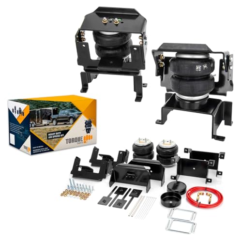


Interpreting OEM exploded blueprints and microfiche records requires understanding Ford’s standardized cataloging system. Rather than using arbitrary sequential numbers, Ford uses an alphanumeric system dividing parts into a prefix, base number, and suffix. Isolating functional assemblies from the parts diagram requires a systematic approach.
- Decode the Functional Base Part Number: Every callout displayed inside an exploded diagram represents a universal base number. For example, callout 12A366 always identifies an ignition coil, callout 8501 identifies a water pump, and callout 3078 references a lower control arm across all Ford vehicle lines. The base number isolates the component’s identity, irrespective of vehicle model or year.
- Locate Platform Prefixes within the Motorcraft Catalog: The complete part number includes a four-character prefix (e.g.,
2L3Z) preceding the base number. The first character identifies the engineering design decade (2= 2002), the second designates the platform vehicle line (L3= F-150 / Expedition), and the fourth defines the responsible Ford engineering division (Z= Ford Customer Service Division / Service Parts). Consulting a master Ford base part number lookup directory confirms the true historical supersession path of your component. - Identify the Design Suffix and Revision Level: Characters following the base number (e.g.,
-AA,-AB,-BA) dictate the design generation, physical revisions, and interior trim or color variations. In mechanical parts diagrams, an update from-AAto-ABrepresents an OEM revision resolving known structural defects, such as reinforced casting webs or updated seal compounds. - Trace Fasteners via Standard Hardware Symbols: Fasteners in the diagram typically feature an “N” prefix (e.g.,
N800937-S439). This indicates standard metric hardware. The suffix denotes the protective coating (e.g.,-S439specifies a zinc-flake phosphate coating engineered to prevent galvanic corrosion when steel bolts pass through aluminum engine structures). - Cross-Reference Cab and Frame Isolator Mounting Positions: When reading the cab-to-chassis structural diagram, review callouts 1000154 (upper rubber cushion) and 1000155 (lower cushion). The 2002 diagram shows 6 body mounting positions for Regular Cab configurations and 8 positions for SuperCab and SuperCrew variants. Verify your wheelbase specifications (120.2″, 138.5″, 139.9″, or 157.4″) before selecting hardware groupings from the diagram key.
Fasteners marked with diamond or triangle symbols on Ford factory schematics denote single-use torque-to-yield (TTY) bolts. This includes cylinder head bolts (base 6065), connecting rod bolts (base 6214), and front hub retainers. These fasteners must be discarded and replaced after removal; their metallurgical yield points are exceeded during initial assembly.
Troubleshooting Common 2002 Ford F150 Parts Diagram Ordering Mistakes


Mismatched part orders often stem from the generational overlap between 1996 and 2004. The 2002 model year sits deep in the 10th-generation production run, but overlaps with both legacy Old Body Style (OBS) platforms and subsequent revisions, leading to common misidentifications in exploded parts catalogs.
Differentiating the 10th Gen PN-96 from the 2004 All-New F-150 (11th Gen) Diagram
The most frequent cataloging error occurs when builders select schematics for an eleventh-generation platform (the “All-New” 2004 F-150, codenamed P221). The 11th-gen layout uses a coil-over-strut front suspension on both 4×2 and 4×4 frames, completely eliminating the torsion bars and independent twin-bracket SLA arms found on the 2002 model. Furthermore, 11th-generation V8 powertrains use 3-Valve heads with variable camshaft timing (VCT solenoids, base 6C535), which are absent on 2002 2-Valve Triton schematics. Attempting to install 2004 P221 front brake rotors on a 2002 frame will fail due to incompatible offset heights and revised spindle diameters.
Preventing Confusion with the 2004 F-150 Heritage Diagram
In 2004, Ford manufactured the 10th-generation truck alongside the 11th-generation redesign, badging it as the 2004 F-150 Heritage. While the 2004 Heritage mechanical blueprints correspond directly with the 2002 chassis architecture, certain parts catalogs list these components under separate inventory headers. When sourcing components for a 2002 truck, verify whether parts tagged under the 2004 Heritage catalog share the XL3Z or 2L3Z engineering prefixes to confirm direct backward compatibility.
Avoiding Legacy Crossover with the 1996 F-150 (9th Gen / OBS) Diagram
Mechanics ordering replacement suspension or axle hardware often confuse 10th-generation diagrams with the 1996 ninth-generation platform. The 1996 OBS platform utilized Ford’s Twin Traction Beam (TTB) or Twin I-Beam front axle architecture featuring large pivot bushings (base 3B203) and radius arms (base 3405). The 2002 F-150 parts diagram shares no steering or front suspension components with 1996 configurations. Additionally, earlier 9th-generation platforms used pushrod Windsor small blocks (5.0L / 5.8L) with traditional mechanical distributors (base 12127), bearing zero dimensional or electrical compatibility with modular 4.6L and 5.4L Triton components.
Wheel Bolt Pattern Variations: 5x135mm vs Legacy 5×5.5 and Metric 6x135mm
A distinct engineering change across 10th-generation F-150s is the 5-lug, 135mm pitch circle diameter (PCD) wheel bolt pattern (callout hub base 1104). The 1996 OBS platform utilized a 5-lug, 5.5-inch (139.7mm) pattern, while the 2004 11th-generation platform transitioned entirely to a 6-lug, 135mm configuration. Technicians must check the wheel stud thread pitch callouts on the 2002 diagram: mid-cycle 2000 revisions shifted hardware from 12mm x 1.75 studs to heavy-duty 14mm x 2.0 studs. Installing an early-run wheel hub assembly on a late 2002 model causes dangerous brake rotor hub-bore clearances and lug nut seating failures.
| Platform Generation | Front Suspension Style | Wheel Bolt Pattern | V8 Valvetrain Architecture |
|---|---|---|---|
| 1996 (9th Gen / OBS) | Twin I-Beam / Twin Traction Beam | 5 x 5.5 in (139.7 mm) | Pushrod 16V Windsor (5.0L/5.8L) |
| 2002 (10th Gen PN-96) | SLA (Coil 2WD / Torsion 4WD) | 5 x 135 mm (M14 x 2.0) | Modular SOHC 2-Valve (4.6L/5.4L) |
| 2004 (11th Gen P221) | Coil-Over Strut Independent | 6 x 135 mm (M14 x 2.0) | Modular SOHC 3-Valve VCT (5.4L) |
2002 Ford F150 Parts Diagram Frequently Asked Questions
Where is the engine VIN code located on a 2002 Ford F-150 schematic?
The engine identification code is located at the 8th digit of the Vehicle Identification Number (VIN), which matches the engine blueprint block in factory service manuals. For the 2002 model year: VIN 2 corresponds to the 4.2L Essex OHV V6; VIN W designates the 4.6L 2V SOHC Romeo Triton V8; VIN 6 designates the 4.6L 2V Windsor engine; and VIN L identifies the 5.4L 2V SOHC Triton V8. Sourcing engine components requires checking this digit, as critical items like the timing cover (base 6019), valve covers (base 6582), and crankshaft main bearing bolt configurations vary between Romeo and Windsor engine architectures.
How do I determine if my 2002 F-150 uses a 4R70W or 4R100 transmission from the diagram?
To identify the transmission model using the diagram, match the oil pan footprint callouts. The 4R70W transmission diagram displays a 14-bolt pan layout roughly square in profile, with the dipstick tube routing directly into the transmission main case. The 4R100 blueprint features an elongated 20-bolt pan perimeter, with an intermediate overdrive clutch cancel switch circuit and dual speed sensors (TSS/OSS, base 7H103) threaded into the outer casing. You can also consult the door jamb Safety Compliance Certification Label under the TR code space: code U denotes the 4R70W, whereas code E denotes the 4R100.
Why do some 2002 F-150 front suspension diagrams show torsion bars while others show coil springs?
The distinction depends entirely on the chassis drive configuration. The 2WD (4×2) diagram displays a front coil spring configuration (base 5310) positioned between the lower control arm and the upper frame bucket. The 4WD (4×4) and 2WD 7700 Payload Group diagrams feature longitudinal torsion bars (base 5B326/5B327) that anchor rearward into a dedicated chassis cross-member. Both configurations use a Short-and-Long Arm (SLA) suspension geometry, but the control arms, knuckles, and frame brackets do not interchange.
How do I identify whether my rear axle is an 8.8-inch or 9.75-inch differential?
Reference the differential carrier housing blueprint (base 4001) and inspect the rear inspection cover bolt pattern. The Ford 8.8-inch axle schematic features a symmetric, oval 10-bolt differential cover. The heavy-duty 9.75-inch axle schematic—standard equipment on all 5.4L models and select towing configurations—features an asymmetric, angular 12-bolt pattern sloping downward toward the passenger-side axle tube. For precise internal service callouts, review a dedicated differential identification guide to match ring gear bolts (base 4216) and pinion shims.
What base part number denotes the fuel tank pressure sensor on the EVAP schematic?
The Fuel Tank Pressure (FTP) sensor is cataloged under base part number 9C052 (or included as an integrated component within the fuel vapor tube and harness assembly base 9J279). On the EVAP system routing schematic, it mounts on the upper surface of the fuel pump module ring on the fuel tank (base 9002). The sensor operates on a 5-volt reference signal from the PCM, outputting between 1.5 and 2.5 volts at atmospheric rest to monitor tank pressure during onboard diagnostic evaporative leak testing.
Step-by-Step Guide to Understanding the 2002 Ford F150 Parts Diagram
Identify – Decode the 10th-gen VIN to verify engine configuration (VIN 6 for 4.2L, W for 4.6L, L for 5.4L) and drive type.
Locate – Find the primary subsystem schematic within the manual, such as the front suspension or modular intake plenum.
Reference – Match the exploded graphic’s numerical index to the factory base part number and standard torque specifications.
Connect/Route – Assemble hardware according to depicted structural layers, seating gaskets and routing lines along designated retention channels.
Verify – Inspect fastener torque, check mating clearances, and cycle mechanical linkages to ensure factory-spec operational travel.
Troubleshoot – Consult subsystem diagnostic schematics to isolate electrical open circuits, vacuum leaks, or misaligned structural brackets.