2005 Toyota Tundra Brake Line Diagram: Routing Guide (2026)

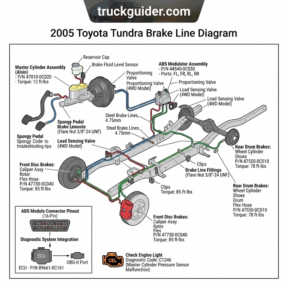
The 2005 Toyota Tundra brake lines route from the tandem master cylinder into the ABS hydraulic control unit along the driver-side frame rail. Front lines branch directly to calipers using M10x1.0 inverted flare fittings, while a dual-run hardline feeds the rear load-sensing proportioning valve (LSPV) and drum or disc assemblies.
📌 Key Takeaways
- Standard tube fittings use M10x1.0 inverted flare nuts requiring an 11-14 lb-ft torque spec.
- Crucial routing splits at the driver-side frame rail ABS actuator and rear axle LSPV.
- Rear brake hard lines along the fuel tank crossmember represent the primary corrosion failure zone.
- ABS ECU communicates fault states via OBD-II, triggering ABS and check engine light warnings.
- Hydraulic bleeding requires a strict sequence: LSPV first, then RR, LR, RF, and LF wheels.
The hydraulic braking network on the first-generation 2005 Toyota Tundra relies on a split-circuit design engineered to balance hydraulic clamping force between the front ventilated disc calipers and rear leading-trailing drum assemblies. Whether your truck features the 4.0L 1GR-FE V6 or the 4.7L 2UZ-FE V8, understanding the hydraulic line architecture is necessary when diagnosing pedal fade, ruptured chassis hard lines, or ABS actuator faults. Corrosive environments severely compromise the factory coated-steel lines, especially along the boxed frame rails adjacent to the fuel tank. This technical guide breaks down the full 2005 Toyota Tundra brake line diagram, detailing fluid routing, flare nut torque specifications, junction block locations, diagnostic leak procedures, and modern nickel-copper (NiCopp) replumbing workflows to restore OEM hydraulic integrity.
2005 Toyota Tundra Brake Line Diagram: Hydraulic System Layout


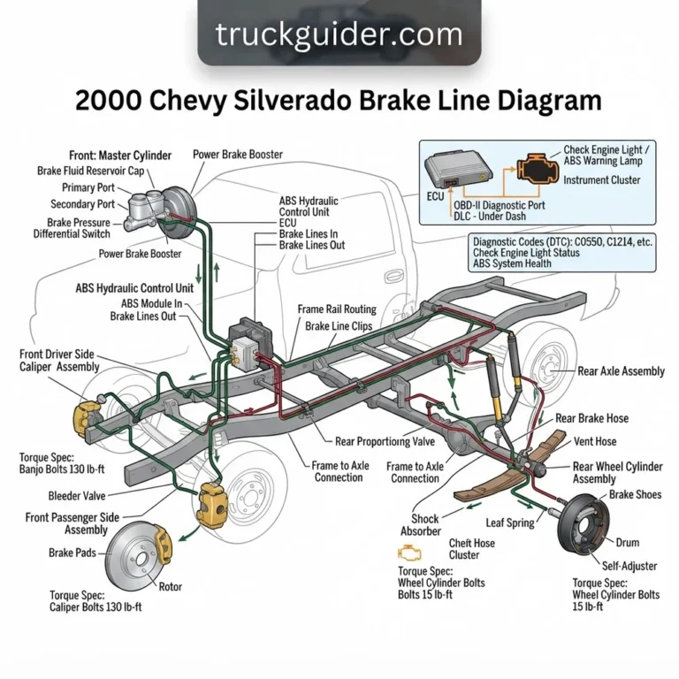
The primary hydraulic circuit originates at the tandem-bore brake master cylinder mounted to the vacuum brake booster on the driver-side firewall. The translucent reservoir features internal baffles and an integrated reed-switch fluid level sensor wired directly to the instrument cluster logic and the Skid Control ECU. Pressurizing the primary piston actuates the front circuit, while the secondary piston supplies hydraulic pressure to the rear axle circuit. OEM engineering utilizes rigid M10x1.0 steel hard lines immediately exiting the master cylinder ports, directing fluid laterally across the bulkhead toward the ABS Hydraulic Control Unit (HCU).



Master Cylinder and ABS Actuator Routing


On models equipped with standard 4-wheel Anti-lock Braking Systems (ABS) or optional Vehicle Stability Control (VSC) and Traction Control (TRAC), the ABS Actuator assembly resides on the passenger-side inner fender apron. Two dedicated steel lines route from the master cylinder ports directly into the top of the ABS HCU. Inside the actuator, a motor-driven pump, internal accumulator chambers, and high-frequency solenoid valves modulate fluid pulses across four discrete channels during wheel lockup events. Unlike simpler engine-bay fluid loops like the closed-circuit coolant flow lines or auxiliary transmission cooler loops, the ABS block operates at transient pressures exceeding 1,800 PSI under panic stops. Inspecting the 2005 Toyota Tundra brake line diagram reveals that four primary hard lines depart this actuator: two dedicated lines routing directly to the front left and front right wheel wells, and two dedicated lines feeding down the right frame rail for the rear braking circuits.
Non-VSC models utilize a single primary rear supply line running from the ABS block back to a frame-mounted proportioning valve, whereas VSC-equipped 2005 Tundras employ dual rear brake lines directly controlled by four-channel independent solenoid circuitry inside the ABS actuator.
Chassis Hard Line and Flexible Drop Hose Integration
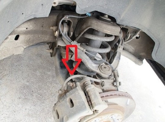
From the ABS actuator, the front left steel line travels along the firewall apron before terminating at a frame bracket behind the driver-side shock tower. The front right line drops directly through the inner apron to a mirrored bracket on the passenger side. At these fixed junction brackets, the rigid lines join multi-layer reinforced synthetic EPDM flexible brake hoses. These hoses accommodate steering angles and dynamic suspension travel before fastening to the multi-piston front brake calipers via brass-sealed banjo fittings.
The rear-bound hard lines traverse the engine compartment, route down the passenger-side chassis rail, and cross over to the driver-side inner frame rail near the transmission crossmember. This routing keeps brake fluid away from the high thermal radiant zones of the catalytic converters and exhaust headers. The chassis hard lines run rearward inside the chassis C-channel, closely tracking the fuel lines and vapor recovery tubing. Ahead of the rear axle assembly, the rigid lines terminate at a frame-mounted chassis bracket. A high-pressure flexible axle drop hose bridges the gap between the suspended chassis frame and the dynamic rear axle housing, terminating at the rear axle junction tee or the Load Sensing Proportioning Valve (LSPV).
Flare Nut Torque Spec Reference and Chassis Routing by Cab Size


Hydraulic line service on the 2005 Tundra demands precise flare geometry and calibrated torque application. Toyota strictly utilizes standard Japanese Industrial Standard (JIS) M10x1.0 inverted flares (double flares) with a 45-degree seat profile on all rigid brake tubing. Installing European DIN/ISO bubble flares or SAE 3/8-24 fittings will ruin internal female seats, warp flare cones, and produce dangerous high-pressure blowouts under emergency braking.


| Connection Location | Thread Size & Flare Style | Hex Size | Torque Spec (ft-lbs / Nm) |
|---|---|---|---|
| Master Cylinder Outlet Ports | M10x1.0 Inverted Double Flare | 10 mm | 11 ft-lbs (15 Nm) |
| ABS Actuator Inlets / Outlets | M10x1.0 Inverted Double Flare | 10 mm | 11 ft-lbs (15 Nm) |
| Front Caliper Banjo Bolts | M10x1.0 Banjo with Copper Crush Washers | 14 mm | 22 ft-lbs (30 Nm) |
| Front Flexible Hose-to-Hard-Line | M10x1.0 Inverted Double Flare | 10 mm / 17 mm | 11 ft-lbs (15 Nm) |
| Rear Axle Drop Hose Connections | M10x1.0 Inverted Double Flare | 10 mm / 17 mm | 11 ft-lbs (15 Nm) |
| Rear Wheel Cylinder Inlets | M10x1.0 Inverted Double Flare | 10 mm | 11 ft-lbs (15 Nm) |
| Hydraulic Bleeder Screws | M7x1.0 (Rear) / M10x1.0 (Front) Taper Seat | 8 mm / 10 mm | 80 in-lbs (9 Nm) |
Chassis dimensions diverge significantly across 2005 Tundra configurations. When referencing intermediate frame line lengths, pay close attention to your cab configuration:
- Regular Cab (128.3-inch Wheelbase, 8-foot Bed): Uses an extended, uninterrupted driver-side frame rail line running 148 inches from the intermediate crossmember to the rear flex bracket.
- Access Cab (128.3-inch Wheelbase, 6.5-foot Bed): Utilizes identical overall chassis hard-line dimensions to the Regular Cab, retaining standard fuel tank dimensions and identical rear bracket offsets.
- Double Cab (140.5-inch Wheelbase, 6.2-foot Bed): Features an extended frame section adding 12.2 inches of intermediate length between the cab-mount transition bracket and the rear axle drop hose. Factory pre-bent replacement hard lines from Access Cab configurations will come up short on Double Cab chassis.
Always torque M10x1.0 tube nuts with an open-ended flare nut crowfoot wrench attached at 90 degrees to your torque wrench handle to maintain true torque spec values and prevent fitting rounding.
Failure Symptoms: Rust Degradation, Warning Lights, and ECU Diagnostic Codes


The primary point of mechanical failure across all first-generation Tundras involves severe structural oxidation along the chassis lines. Road brine, winter salt, and trail debris collect directly behind the chassis-mounted plastic retention clips and on the upper flange of the boxed frame sections. This moisture retention triggers galvanic corrosion beneath the green terne-coating of the original steel tubing, leading to pinhole perforations.
Frame Rail Corrosion and Hydraulic Pressure Loss
The most vulnerable failure area sits inside the driver-side frame rail cavity directly sandwiched between the outer frame face and the plastic 26.4-gallon fuel tank. Technicians cannot inspect this hidden section during standard bay walk-throughs without a fiber-optic borescope. Because this zone was central to the wide-reaching Toyota Frame Rust Campaign, road corrosion often rots out the chassis hard line long before the frame perforates through. Under hard pedal application, oxidized tubing yields at the seam, producing a catastrophic drop in circuit pressure.


The physical symptoms manifest instantly:
- Spongy brake pedal dropping rapidly past the normal engagement height down to the floorboards.
- Noticeable rearward or forward vehicle nose dive caused by the complete failure of one hydraulic isolation half.
- Rapid depletion of DOT 3 or DOT 4 fluid inside the master cylinder reservoir chambers.
- Heavy wet residue pooling over the rear axle differential casing, inside the driver-side frame channel, or dripping off the fuel tank skid plate.
Continuing to drive with a perforated brake line will quickly starve the secondary master cylinder bore, introducing massive air pockets into the ABS actuator and leaving only minimal emergency front stopping power.
ABS Actuator Faults and OBD-II Check Engine Light Triggers


A severe hydraulic rupture immediately alters circuit dynamics, causing the instrument cluster red BRAKE warning light to glow continuously as the fluid level switch drops. Simultaneously, the Skid Control ECU detects wheel speed variance versus hydraulic deceleration models. When the ABS pump engages during an unstable stop, pressure sensor differentials trigger chassis trouble codes readable through the cabin OBD-II diagnostic port using an advanced scan tool.
Common diagnostic codes associated with hydraulic line rupture and ABS actuator starvation include:
- DTC C0215: Rear Speed Sensor Left Circuit Malfunction (often flagged when fluid covers the rear tone ring).
- DTC C1225 / C1226: Open or Short in Hydraulic Control Circuit / Solenoid Valve Circuit failure.
- DTC C1246: Master Cylinder Hydraulic Pressure Sensor Malfunction.
- DTC C1251: Open in ABS Pump Motor Circuit (logged if the ECU pump continuously runs attempting to pressurize a leaking channel).
In certain VSC-equipped 2005 Tundras, chassis faults share communication buses with the main engine ECU. When system safety logic defaults to limp-mode, the instrument cluster illuminates the VSC OFF, TRAC, and ABS lamps, occasionally accompanying a general check engine light if auxiliary sensor data falls out of calibration range. While an engine diagnostic code typically points toward ignition misfires or variable valve timing issues along the timing chain assemblies, a simultaneous red brake indicator and amber ABS light identifies an open hydraulic loop.
Inspecting the 2005 Toyota Tundra Brake Line Diagram for Leaks



To accurately diagnose hydraulic line degradation before catastrophic bursting occurs on the road, follow this structured, shop-grade inspection protocol:
- Perform a Static Level and Master Cylinder Inspection: Park the vehicle on level ground, shut off the ignition, and unlatch the hood. Clean the exterior master cylinder reservoir with brake cleaner. Inspect the fluid level against the MIN and MAX lines. Check the underside of the master cylinder body where it mates to the vacuum booster face; wetness here signifies a failed rear piston seal leaking brake fluid directly into the booster diaphragm.
- Execute Booster Vacuum Depletion and Static Pedal Pressure Test: With the engine off, pump the brake pedal five to six times until it firms up, dissipating all residual vacuum assist. Press down firmly on the pedal and hold continuous force for 45 seconds. If the pedal steadily creeps downward toward the carpet, hydraulic pressure is escaping through an external line blowout, a blown caliper piston seal, or internally through bypassing master cylinder piston cups.
- Raise and Support Vehicle to Expose the Chassis Hard-Line Route: Lift the vehicle using a commercial two-post hoist or heavy-duty jack stands placed under the factory frame lift points. Remove all four road wheels. Using an inspection light, trace the primary chassis lines departing the ABS actuator down along the passenger-side wheel apron, across the crossmember, and down the driver-side frame rail.
- Scrutinize the Fuel Tank Cavity and Frame Brackets: Direct your inspection light between the driver-side inner frame rail and the fuel tank. Look for the factory plastic routing clips. Probe the steel line surfaces with a brass wire brush. If you observe thick, flaky rust lamellae (“delamination”) or damp dark staining, the steel walls are dangerously compromised and require total replacement.
- Inspect the Axle Drop Hose and Rear Brake Tee / Junction Block: Locate the flexible rubber drop line spanning from the rear frame crossmember to the rear axle housing. Check the outer EPDM casing for deep ozone checking, stress cracking, bulges under pressure, or weeping at the metal crimp collars. Trace the lines out from the rear brake tee junction block to the left and right wheel cylinders. Check behind the brake drum backing plates; oily deposits around the lower drum lip indicate either a leaking axle shaft oil seal or a failed wheel cylinder piston boot saturating the friction linings.
- Examine Caliper Banjo Interfaces and Bleeder Screws: Wipe down all four bleeder screws and caliper banjo bolts. Have an assistant depress the brake pedal with the engine idling to generate maximum power-assisted hydraulic pressure (often exceeding 1,200 PSI). Inspect all junction seats, banjo crush washers, and the rigid-to-flexible line clips using a mechanics inspection mirror. Any visible fluid weeping or bubbling confirms an immediate seat failure requiring disassembly with a dedicated 10 mm flare nut wrench.
Replacing Hard Lines: Fuel Tank Drop vs. NiCopp Routing Methods
Replacing failed steel brake lines on a 2005 Tundra presents an installation challenge: the original single-piece pre-bent chassis line spans from the transmission crossmember to the rear axle, tucked tightly above the fuel tank and across rear frame gussets. Technicians have two primary methods for executing this repair:


Method 1: The Factory OEM Approach (Dropping the Fuel Tank)
- Preparation: Disconnect the battery ground cable. Siphon or drain fuel from the tank until empty to reduce static weight. Disconnect fuel filler neck lines, EVAP vapor harnesses, and the main fuel pump module electrical connection.
- Tank Dropping: Support the tank with a transmission jack, remove the front and rear tank support strap bolts, and carefully lower the tank clear of the frame rail.
- Pre-Bent Line Installation: With the tank removed, unclip the rusted lines from the OEM plastic organizers. Maneuver rigid OEM pre-bent steel replacement tubes into the factory frame channels, click them into new retention clips, and torque all connections to specification.
- Assessment: This method keeps the underbody 100% true to original factory schematics. However, it demands substantial shop lift time, risks stripping seized tank strap hardware, and requires disturbing aged fuel and EVAP components.
Method 2: The Modern Technician Approach (Routing Flexible NiCopp Tubing)
- Material Selection: Procure a 25-foot coil of seamless 3/16-inch (4.75 mm) Nickel-Copper (NiCopp) alloy tubing. NiCopp consists of roughly 90% copper and 10% nickel, meeting SAE J1047 and ISO 4038 standards for burst pressure resistance up to 15,000 PSI while being totally immune to road salt corrosion.
- Snaking Without Tank Removal: Because NiCopp is ductile and highly malleable, you can hand-form the tubing without external tube benders. Fish the coiled NiCopp tubing through the frame pocket between the frame rail and the fuel tank without dropping the tank assembly.
- Flare and Fitting Preparation: Cut the tubing with a dedicated mini tubing cutter. Deburr the inner and outer tube edges with a reamer. Slide new JIS M10x1.0 inverted flare tube nuts onto the line facing outward. Use an on-vehicle double flaring tool to form precise 45-degree inverted SAE/JIS flares.
- Securing and Chafing Defense: Secure the custom-routed line inside the frame using rubber-cushioned stainless steel P-clamps. Never allow copper-nickel lines to vibrate directly against bare steel frame edges or fuel line brackets.
- Load Sensing Proportioning Valve (LSPV) Hookup: On 2005 models equipped with an LSPV mounted to the rear crossmember, carefully route both the main feed line and the return line into their respective ports. Keep the bleeder screw oriented upward. Adjust the mechanical LSPV spring rod attached to the rear differential to factory ride height specs to guarantee correct dynamic hydraulic split between empty and loaded hauling states.
Chassis Hydraulic Bleeding Sequence
After installing new lines, you must purge all air from the system. If the master cylinder ran dry, bench bleed it before chassis bleeding. Flush the entire network using clean, fresh DOT 3 or DOT 4 brake fluid. Because the ABS actuator retains air pockets easily, follow Toyota’s exact reverse-hydraulic distance sequence:
- Load Sensing Proportioning Valve (if equipped): Bleed the LSPV upper bleeder valve first to purge air from the long frame line run.
- Rear Passenger Side (RR): Longest remaining hydraulic circuit path.
- Rear Driver Side (LR): Shorter rear axle circuit run.
- Front Passenger Side (FR): Longest engine bay cross-run.
- Front Driver Side (FL): Shortest line closest to the master cylinder.
Maintain fluid level inside the master cylinder reservoir throughout the process. Allowing the reservoir to drop below the minimum threshold will drag air back into the ABS pump chambers, requiring an electronic bi-directional scan tool command via OBD-II to cycle the internal ABS solenoids.
2005 Toyota Tundra Brake Line Diagram Technical Troubleshooting FAQ
Which flare style does Toyota specify for the 2005 Tundra brake lines?


The 2005 Toyota Tundra exclusively utilizes JIS M10x1.0 inverted flares (standard 45-degree double flares). Never use European-style 90-degree DIN bubble flares or domestic 3/8-24 SAE threads. Using the incorrect flare design will crush the internal sealing seat within the ABS actuator or wheel cylinder, causing an irreversible hydraulic leak.
Why does the ABS light or check engine light illuminate during a line rupture?
When a chassis hard line ruptures, line pressure plummets. Under braking, the affected wheel locks or experiences zero deceleration compared to the remaining functional wheels. The wheel speed sensors transmit disparate velocity signals to the Skid Control ECU. The ECU senses this imbalance, flags a diagnostic code (such as DTC C1225 or C0215), and disengages the ABS system, illuminating the ABS, BRAKE, and VSC lights on the dashboard.
Can you bypass the rear load sensing proportioning valve (LSPV)?
While some off-road enthusiasts bypass the frame-mounted LSPV by installing a manual knob proportioning valve or coupling the lines directly, doing so on a street-driven truck changes rear brake bias. Without load sensing, an unladen truck bed can cause aggressive rear wheel lockup under moderate braking, potentially inducing severe spin-outs. If your LSPV body is leaking, the safest repair is replacing it with a verified OEM valve assembly and properly adjusting the tension spring.
How does engine bay thermal load affect hard lines near the coolant flow paths?
Toyota engineers routed the front brake lines along the fender skirts rather than low down against the engine block to shield hydraulic fluid from extreme operating temperatures. Brake fluid operates best below 140°F (60°C); proximity to unshielded exhaust manifolds, high-temperature oil pressure sending ports, or hot coolant flow radiator hoses can boil moisture-contaminated DOT 3 fluid. Boiling drops the fluid’s boiling point, generating vapor bubbles that cause a spongy brake pedal and loss of braking power.
What is the exact tube diameter used across the factory 2005 Tundra braking system?


The factory chassis hard lines use 3/16-inch (nominal 4.75 mm) rigid steel tubing across all cab sizes and engine layouts. When fabricating replacement lines with NiCopp alloy, consistently use 3/16-inch tubing coupled with M10x1.0 long-thread inverted flare tube nuts to ensure a safe, leak-free seal across all chassis junction blocks.
Step-by-Step Guide to Understanding the 2005 Toyota Tundra Brake Line Diagram
Identify – Trace the master cylinder ports down to the ABS modulator block using the schematic to distinguish primary and secondary hydraulic circuits.
Locate – Find the specific chassis clip mounting points along the inner left frame rail, noting where hard lines cross near the fuel tank and exhaust heat shields.
Reference – Cross-reference the port stamping on the ABS valve body with your diagram to verify the correct corner output (FL, FR, RL, RR).
Connect/Route – Route replacement 3/16-inch brake lines following factory bends, securing them into chassis isolators to avoid abrasion and vibration fatigue.
Verify – Tighten all M10x1.0 line fittings to the factory 11-14 lb-ft torque spec using a flare nut wrench, avoiding over-torquing the valve ports.
Troubleshoot – Bleed the hydraulic circuit, then connect an OBD-II scanner to verify no ABS diagnostic code remains stored in the vehicle ECU.