2000 Toyota Tundra Fuel Line Diagram: Routing & Repair (2026)

The 2000 Toyota Tundra fuel line routing originates at the in-tank pump assembly, sending pressurized fuel via a 5/16-inch steel feed line along the driver-side inner frame rail through the inline filter to the engine rails. A parallel 1/4-inch fuel return line routes excess fuel back from the pressure regulator, maintaining 38–44 PSI.
📌 Key Takeaways
- Operating fuel pressure must measure 38–44 PSI with vacuum disconnected and 31–37 PSI connected.
- Main supply line runs 5/16-inch hardline along the driver-side inner frame rail directly to the inline filter.
- Fuel line flare nut connections at the filter require precisely 22 ft-lbs (30 Nm) to avoid thread distortion.
- Severe corrosion at frame rail bracket hold-downs is the leading cause of high-pressure pinhole leaks.
- DIY replacement is straightforward for outer lines, but drop the tank or seek professional aid if tank vapor/return fittings fracture.
The fuel delivery infrastructure on the first-generation 2000 Toyota Tundra (XK30/XK40 platform) represents a transition-era electronic fuel injection (EFI) layout engineered around high reliability and steady manifold-referenced pressure regulation. Whether equipped with the standard 3.4L 5VZ-FE V6 or the flagship 4.7L 2UZ-FE DOHC 32-valve V8, the fuel circuit relies on a closed-loop supply and return architecture. Accurate diagnostic tracing, frame restoration, and component replacements demand an exacting breakdown of the fuel circuit geometry. Using an authoritative 2000 Toyota Tundra fuel line diagram allows technicians to isolate high-pressure delivery runs from low-pressure return pathways and evaporative emissions (EVAP) circuits. Understanding how these hydraulic conduits interface with under-chassis clips, the frame-mounted inline filter, and the fuel rail assemblies ensures repairs maintain factory tolerances, safety protocols, and correct system pressures across all engine load stages.
Schematic representation of the 3-line under-chassis bundle, in-tank modular sender, inline filter, 2UZ-FE fuel rail distribution, and EVAP canister circuit.
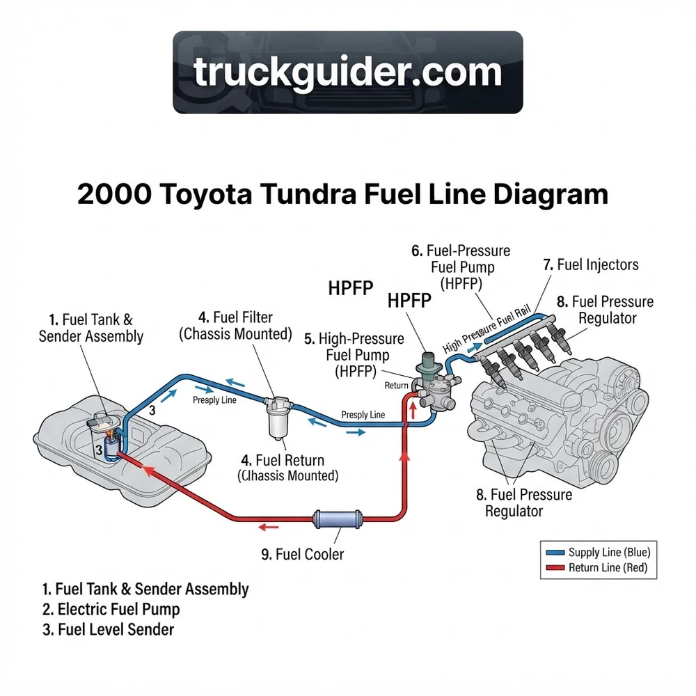
2000 Toyota Tundra Fuel Line Diagram and Chassis Routing


Tracing the fuel lines on the 2000 Toyota Tundra requires analyzing the three primary conduits that make up the under-chassis bundled run along the inner channel of the driver-side (left-hand) frame rail. Unlike modern return-less systems that deadhead pressure at the tank module, the first-generation Tundra features an active circulating loop. Fuel is continually delivered to the intake manifold vicinity and routed back to dissipate thermal soak from the engine compartment.
The bundle originates at the upper sending unit flange located on top of the 26.4-gallon steel fuel tank. From the tank hat, three flexible high-pressure polyamide-reinforced rubber jumper hoses transition fuel into fixed steel hard lines mounted to the chassis:
- High-Pressure Fuel Supply Line: Measures 5/16-inch (8 mm outside diameter) cold-rolled steel tubing with an electro-galvanized zinc and nylon fluoropolymer coating. This line routes pressurized fuel directly from the in-tank turbine pump to the inlet port of the inline fuel filter. From the filter outlet, the high-pressure line runs forward along the frame, transitions up the front inner wheelhouse splash apron, and terminates at the rear of the bank 1 (left/driver side) fuel rail via a dedicated flexible jumper hose and banjo junction.
- Fuel Return Line: Measures 1/4-inch (6 mm outside diameter) rigid steel tubing. This conduit connects to the outlet barb of the vacuum-referenced fuel pressure regulator mounted at the engine compartment fuel rail. It captures surplus fuel bypassed by the regulator valve and directs it back down the inner frame channel into the fuel tank pickup reservoir, stabilizing fuel temperatures and preventing hydraulic hammer.
- EVAP / Vapor Line: Measures 5/16-inch (8 mm outside diameter) steel tubing. This vapor circuit interfaces with the roll-over check valves atop the fuel tank, routing hydrocarbon vapors forward to the engine bay purge VSV (Vacuum Switching Valve) and the chassis-mounted charcoal canister assembly, situated adjacent to the spare tire carrier under the bed.
On the Toyota 4.7L 2UZ-FE V8, fuel distribution splits once the high-pressure line enters the engine valley. The bank 1 fuel rail routes directly across the front of the intake manifold via an arched crossover hard pipe to supply the bank 2 (passenger side) rail. Fuel flows down both rails to the eight multi-hole port injectors before reaching the diaphragm pressure regulator at the rear exit of bank 2. In contrast to diesel fuel architectures—which employ an external fuel cooler to drop return temperatures under heavy injection cycles—the Tundra relies entirely on ambient airflow across the exposed underside frame rails to shed thermal load before fuel re-enters the reservoir.
The factory hard lines are secured inside molded nylon isolator clips riveted directly to the inside web of the C-channel frame rail. Over decades of operation, road silt, moisture, and road de-icers pack inside these isolator brackets, creating concentrated corrosion pockets directly beneath the plastic retention tabs that compromise structural tube integrity.
2000 Toyota Tundra Fuel Line Diagram: Every Component Detailed


A comprehensive reading of the 2000 Toyota Tundra fuel line diagram requires identifying each electro-mechanical, filtering, and hydraulic component within the network. Heavy-duty diesel systems often implement an external fuel bowl, water separator, manual primer pump, or an engine-mounted fuel heater alongside a high pressure fuel pump (HPFP) controlled by an injection pressure regulator. By comparison, the gasoline-powered 2000 Tundra uses an internal tank pickup, an inline filter canister, and manifold-vacuum-balanced regulation.
| Component | OEM Part / Spec Reference | System Function | Connection Type & Physical Location |
|---|---|---|---|
| In-Tank Fuel Pump Assembly | Denso 195130-1020 / Toyota 23221-50060 (12V DC, 4.5–6.0 Amps) | Submerged electric turbine pump drawing fuel through an inlet strainer sock to generate primary feed pressure (45–60 PSI deadhead). | Internal locking cradle inside fuel tank; interfaces to tank hat via submersible high-pressure rubber connector hose. |
| Inline Fuel Filter | Toyota 23300-50090 / 23300-50110 (10-micron pleated cellulose/synthetic media) | Traps particulate matter and sediment before fuel enters the injector distribution manifolds. | M14 x 1.5 female inverted flare nut fittings on inlet/outlet; secured via stamped steel bracket to the inner driver frame rail under the cab. |
| Fuel Rails (Bank 1 & Bank 2) | Toyota 23811-50040 (Left) / 23812-50040 (Right) | Extruded aluminum fuel delivery galleries acting as pressurized reservoirs for the fuel injectors. | Bolted to lower intake manifold runners; interconnected at the front by a brazed steel crossover pipe using integrated union bolts. |
| Fuel Pressure Regulator (FPR) | Toyota 23280-50050 (Diaphragm-operated spring-loaded seat) | Modulates line rail pressure relative to manifold vacuum: 38–44 PSI (vacuum line disconnected) / 31–37 PSI (vacuum applied). | O-ring sealed slip-joint retention into rear of Bank 2 fuel rail; 1/4-inch push-on hose barb routing to the steel fuel return line. |
| Fuel Pulsation Damper | Toyota 23270-50010 (Internal spring and screw indicator) | Absorbs hydraulic pressure shockwaves generated by the rapid opening and closing cycles of the injector pintles. | M12 x 1.25 banjo thread integration with aluminum crush washers at the entry point of the Bank 1 fuel rail. |
Unlike diesel architectures with low-pressure lift pumps, common rail manifolds, and engine-driven injection units, the 2000 Tundra uses an all-electronic single-stage delivery profile. While diesel engines rely on a dedicated fuel injection timing circuit, Toyota’s multi-point EFI meters fuel by varying injector pulse width (duration) over stabilized line pressure maintained continuously by the mechanical diaphragm regulator.
Fuel Return Line Leaks and Common First-Gen Tundra Symptoms


Corrosion-induced hydraulic and vapor failures are well-documented across early first-generation Tundras, particularly those operated in coastal regions or the North American Rust Belt. Because the 2000 model year utilizes uncoated or thin-coat mild carbon steel for underbody fuel plumbing, progressive oxidation eventually degrades the exterior tube walls. Technicians must differentiate between failures on the high-pressure supply line, the fuel return line, and the EVAP circuit.
A pinhole leak on the high-pressure fuel supply line can atomize fuel into a combustible aerosol under 40+ PSI of line pressure. A leak occurring near the driver-side frame rail is situated directly adjacent to exhaust pipes and catalytic converter heat shields. Never operate the engine if liquid fuel or persistent raw fuel odors are present.
Pinhole Rust Leaks and Frame Mounting Corrosion
The most common failure mode is a pinhole rust leak forming on the fuel return line or high-pressure supply line directly beneath the mid-chassis retention clips. Dirt and moisture become trapped between the frame rail steel and the line clip’s plastic retention body. This prevents the metal line from drying, accelerating electrolytic rust. Because the fuel return line operates under low pressure (typically below 10 PSI), return leaks rarely display dynamic spraying. Instead, they produce a continuous seep that coats the outer frame rail, creating a sticky residue of road grime and dried fuel varnish.
Diagnostic Symptoms Across Operational Lines
- Fuel Return Line Breach: Results in persistent fuel odors around the middle of the vehicle and wet frame surfaces behind the transmission crossmember. System supply pressure often remains intact during open-throttle running because the restriction occurs downstream of the regulator. However, during extended cranking, air ingress into the return line can compromise the siphon effect in the tank sender assembly, causing extended hot-start crank times.
- High-Pressure Fuel Supply Line Failure: Causes a rapid loss of rail operating pressure. Symptoms include pronounced engine hesitation under load, lean condition misfire codes (DTC P0171, P0174), heavy liquid pooling along the front wheelhouse splash panel, and visible pressure drop on a mechanical gauge connected to the service tap.
- EVAP / Vapor Line Rust Perforation: Rarely yields visible liquid leaks. Instead, breaches trigger check engine illumination with diagnostic trouble codes P0440 (EVAP System Malfunction), P0442 (Small Leak Detected), or P0446 (EVAP Vent Control Circuit). These leaks can be located by introducing mineral-oil-based smoke into the fuel filler neck test port and checking the hard lines with an ultraviolet light.
Acceptable fuel system holding pressure: Upon turning the ignition OFF, the fuel rail circuit must maintain a minimum residual pressure of 21 PSI (147 kPa) for at least 5 minutes. A rapid decay below 20 PSI within 60 seconds indicates a ruptured supply check-valve, a weeping injector, a failed fuel pressure regulator diaphragm, or an external line perforation.
Replacing Lines on the 2000 Tundra Fuel Piping Diagram
Replacing failed steel lines on the 2000 Toyota Tundra involves servicing tight flare connections, preventing thread galling on the frame-mounted filter, and routing replacement sections safely past suspension mounts. Follow this factory-grade service procedure to restore fuel containment integrity.
Required Tools and Materials
- 10mm, 12mm, 14mm, 17mm, and 19mm flare nut wrenches (tubing wrenches)
- Standard socket and ratchet set (10mm to 17mm)
- PB Blaster or equivalent penetrating solvent
- High-pressure fuel injection rated replacement lines (5/16-inch supply, 1/4-inch return) — NiCopp (nickel-copper alloy) or pre-bent OEM assemblies
- OEM Toyota replacement crush washers for banjo bolt unions (Part No. 90430-12026)
- Fuel pressure gauge with Toyota banjo adapter harness
- Class B dry chemical fire extinguisher
Step-by-Step Removal and Installation Procedure
- Depressurize the Hydraulic Circuit: Access the engine bay underhood fuse and relay block (located forward of the driver-side battery). Remove the plastic cover and locate the 15A EFI Fuse and the EFI Circuit Opening Relay. Pull the 15A EFI fuse from its socket. Turn the ignition switch to START and crank the engine for 5 to 10 seconds. The engine will crank, run briefly, and stall from fuel starvation. Crank for an additional 3 seconds to clear residual line pressure. Turn the ignition switch OFF and disconnect the negative battery cable with a 10mm wrench.
- Disconnect the Line Junctions at the Filter: Locate the inline fuel filter mounted on the inside web of the driver-side frame rail beneath the driver’s door position. Liberally apply penetrating solvent to the exposed threads of the M14 x 1.5 flare nut fittings on both the forward and rearward line connections. Allow the solvent to soak for 15 minutes. Seat a 14mm flare nut wrench on the line nut and a 19mm open-end wrench on the fuel filter end-hex to act as a counter-hold. Break the flare nut loose smoothly. Never apply torque without the counter-hold wrench in place, or the bracket will bend and kink the adjoining hard pipe.
- Release Frame Isolator Brackets: Using a 10mm socket, remove the retaining bolts securing the nylon clamp brackets along the driver-side inner frame rail. Carefully pry the plastic retaining tabs open using a non-marring trim tool to release the fuel supply, return, and EVAP pipes from their mounting points. Inspect the frame channel behind each clip for scale rust that requires treatment.
- Disconnect the Engine Bay Banjo and Hose Interfaces: At the rear of the bank 1 cylinder head, access the banjo union bolt connecting the frame supply jumper line to the fuel rail pulsation damper. Position an absorbent shop rag beneath the junction. Using a 17mm socket, break the banjo bolt loose and discard the old aluminum/copper crush washers. Loosen the spring-tension clamp securing the 1/4-inch rubber return hose to the fuel pressure regulator barb, and gently twist the hose off the connection nipple.
- Drop the Tank Connections (If Replacing Rear Runs): If corrosion extends behind the fuel filter toward the tank hat, support the fuel tank with a transmission jack. Remove the two 14mm tank strap bolts, lower the tank roughly 6 inches, and disconnect the quick-connect electrical harnesses and rubber flex jumpers connecting the hard lines to the sender hat. Press the plastic quick-release tabs inward while backing the line off the steel barb.
- Install Replacement Hard Lines: When replacing rusted sections with NiCopp alloy lines, bend the new tubing to match the original factory bends using a dedicated tubing bender. Maintain a minimum of 1-inch clearance between fuel conduits and brake lines, electrical harnesses, or moving suspension components. Hand-thread all flare nut fittings into the fuel filter and rail connections to avoid cross-threading the fine M14 x 1.5 pitch threads.
- Torque Fittings to OEM Specifications: Tighten all threaded interfaces with calibrated tools:
- Fuel filter flare nuts (14mm): Torque to 22 to 29 ft-lb (30 to 39 N·m) while counter-holding the filter hex.
- Engine rail banjo bolts (17mm): Torque to 25 to 30 ft-lb (34 to 41 N·m) utilizing brand-new crush washers.
- Tank bracket retaining bolts: Torque to 29 ft-lb (39 N·m).
- Re-energize and Pressure Test System: Reinstall the 15A EFI fuse into the underhood fuse box and reconnect the negative battery cable. Cycle the ignition switch to the ON position (without cranking) for 5 seconds, then return to OFF. Repeat this process three times to cycle the fuel pump and pressurize the lines. Inspect every connection point—especially the flare nuts at the inline filter and the engine banjo fitting—using an inspection mirror and dry lint-free cloth to confirm the system is leak-free before starting the engine.
2000 Toyota Tundra Fuel Line Diagram Technical Questions
What are the exact line sizes used in the 2000 Tundra fuel line diagram?
The 2000 Toyota Tundra chassis employs three distinct tube sizes along the frame rail: the high-pressure fuel supply line measures 5/16-inch outside diameter (8 mm) with M14 x 1.5 inverted flare terminations at the filter; the fuel return line measures 1/4-inch outside diameter (6 mm); and the EVAP emissions vapor conduit measures 5/16-inch outside diameter (8 mm). When fabricating custom replacement sections, ensure you use tubing matched to these exact diameters to maintain factory volumetric flow and allow proper retention in the frame clips.
What static and dynamic fuel pressures should you measure on the 4.7L 2UZ-FE?
According to factory specifications, baseline fuel system pressure with the vacuum sensing hose disconnected from the fuel pressure regulator must read between 38 and 44 PSI (265 to 304 kPa). When the vacuum hose is reconnected at idle speed, manifold vacuum pulls the regulator diaphragm open, reducing rail pressure down to 31 to 37 PSI (216 to 255 kPa). If baseline pressure falls below 35 PSI, inspect the inline filter for sediment blockage or test the in-tank pump for low supply voltage.
Can you substitute rubber fuel hose for rotted hard supply lines on a 2000 Tundra?
Standard SAE 30R7 low-pressure rubber fuel hose must never be substituted for the high-pressure supply line. The high-pressure circuit experiences operational spikes up to 60 PSI, which can rupture standard fuel lines. If temporary or flexible repairs are necessary, use only SAE 30R9-rated fuel injection hose secured with rolled-edge fuel injection clamps, not standard worm-gear clamps. However, best mechanical practices require replacing chassis runs with seamless steel or seamless annealed CuNi (NiCopp) tubing to maintain heat, abrasion, and crash-impact resistance.
Why does my 2000 Tundra throw EVAP codes after replacing fuel hard lines?
Installing new chassis fuel hard lines requires disturbing the adjacent 5/16-inch EVAP vapor line, the chassis charcoal canister, and its connected vacuum hoses. If an EVAP code such as P0440, P0441, or P0442 appears immediately after service, inspect the connections at the fuel tank rollover valves, check for micro-cracks in the aging vacuum hoses at the chassis canister, and verify the quick-connect seals at the EVAP service port. Pinched or misrouted vapor lines will trigger system test failures during the engine control module’s (ECM) cold-start EVAP monitor cycle.
Does the 2000 Toyota Tundra fuel system require an auxiliary fuel cooler or fuel heater?
No. Factory 2000 Toyota Tundras (both 3.4L V6 and 4.7L V8 gasoline variants) do not utilize a fuel cooler, fuel heater, manual primer pump, or an engine-mounted high pressure fuel pump (HPFP). These components are exclusive to direct-injection gasoline systems or heavy-duty diesel injection systems. The 2000 Tundra’s electronic multi-port design relies on a continuous return flow directly through the chassis tubing to regulate fuel temperatures, preventing vapor lock under standard operating conditions.
2000 Toyota Tundra Fuel Line Diagram: Frequently Asked Questions
What are the main components of the 2000 toyota tundra fuel line diagram?
The system includes the in-tank turbine fuel pump, fuel tank vapor vent lines, frame-mounted canister filter, high-pressure hardline feed, fuel return line, rubber flex hoses, dual injector fuel rails, vacuum-operated fuel pressure regulator, and pulsation damper, balancing port-injection pressure across all cylinders.
What are symptoms of a failing 2000 toyota tundra fuel line diagram pump?
Symptoms include extended engine cranking, intermittent engine sputtering under heavy acceleration, loud whining from the fuel tank, severe power loss climbing grades, and lean diagnostic trouble codes such as P0171 or P0174 caused by low operating rail pressure dropping below 30 PSI under load.
How do I diagnose a fuel leak in 2000 toyota tundra fuel line diagram?
Inspect the driver-side frame rail where steel lines clip into plastic chassis brackets, checking for road-salt corrosion and wet residue. Prime the system using ignition cycle position II without cranking, then inspect flare fittings at the fuel filter bowl and rail quick-disconnects using an inspection mirror.
What is the fuel pressure spec for 2000 toyota tundra fuel line diagram?
Static regulated fuel pressure on both 3.4L V6 and 4.7L V8 engines is 38 to 44 PSI with the regulator vacuum hose disconnected and pinched. Reconnecting vacuum should cause the injection pressure regulator to drop rail pressure down to roughly 31 to 37 PSI at idle.
How long does 2000 toyota tundra fuel line diagram fuel pump last?
The OEM Denso in-tank fuel pump typically lasts between 150,000 and 200,000 miles. Lifespan diminishes prematurely if the vehicle is frequently operated on an empty tank, which deprives the submerged high pressure fuel pump assembly of essential cooling and lubrication provided by liquid gasoline.
Can I replace the 2000 toyota tundra fuel line diagram fuel filter myself?
Yes, using basic hand tools and a 14mm flare nut wrench. Relieve system pressure via the EFI fuse, support the filter body with a 19mm backup wrench, and loosen line nuts along the inner frame. Always install fresh crush washers and inspect line flares for pitting.