2006 Chevy Silverado ABS Brake Line Diagram: Routing Guide 2026

The 2006 Chevy Silverado ABS brake line layout routes two lines from the master cylinder (1/2-inch and 7/16-inch fittings) down to the Brake Pressure Modulator Valve (BPMV) mounted inside the driver-side frame rail. Four outlet lines distribute hydraulic fluid: two forward to the front calipers and two running rearward to the rear axle junction block.
📌 Key Takeaways
- Master cylinder feeds the ABS BPMV block via primary M12x1.0 and secondary M11x1.5 threaded flare ports.
- Lines run along the inside driver frame rail where road debris and salt create the highest corrosion risk.
- Strictly adhere to the 14 to 19 lb-ft (19-26 Nm) fitting torque spec into the aluminum valve body.
- Fluid leaks cause spongy pedals, illuminate the check engine light or ABS indicator, and log a diagnostic code.
- Replacing line kits is DIY-friendly, but purging air from the ABS ECU requires a bi-directional OBD-II scanner.
Diagnosing, repairing, or replumbing the brake hydraulic circuit on a GMT800 platform requires an exact understanding of the master cylinder, proportioning mechanisms, and electronic modulator routing. The 2006 Chevrolet Silverado utilizes an advanced Kelsey-Hayes or Bosch ABS system (depending on whether the truck is equipped with standard four-wheel ABS or the JL4 StabiliTrak option) mounted to the inner driver-side frame rail. Corroded hardlines, sponge pedal conditions, or erratic valve actuation demand a systematic approach to line routing. This technical manual provides an authoritative breakdown of the hydraulic circuits, port assignments, diagnostic failure points, and pressure bleeding protocols required for professional chassis repair.
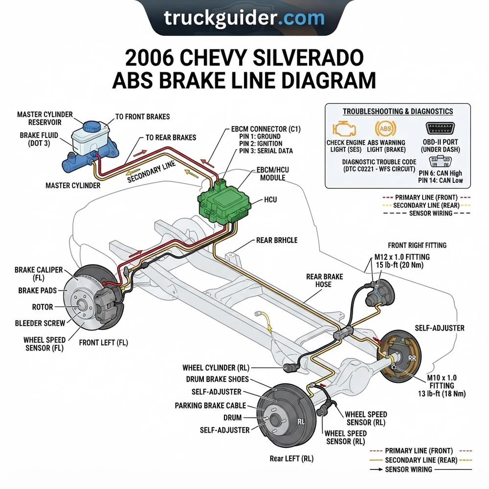
2006 Chevy Silverado ABS Brake Line Diagram and Port Layout Guide




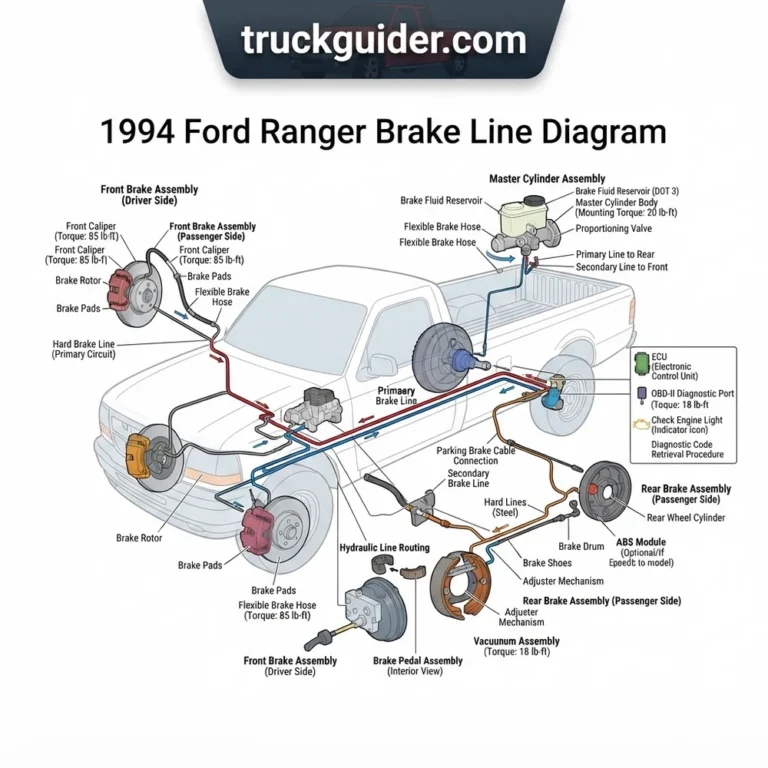
The hydraulic brake system on the 2006 Silverado functions via an isolated dual-circuit system partitioned within the Brake Pressure Modulator Valve (BPMV). Fluid departs the cast-aluminum tandem master cylinder through two distinct ports: the primary port (rearward, serving the front calipers) and the secondary port (forward, servicing the rear wheel circuit). These primary and secondary hardlines span downward along the inner fender, routing fluid directly into the inlet ports of the frame-mounted ABS hydraulic modulator block, which sits directly beneath the driver-side cab floor.


Inside the BPMV, hydraulic pressure is regulated by internal solenoid valves (inlet and outlet valves for each wheel track) controlled by the Electronic Brake Control Module (EBCM). In standard non-StabiliTrak configurations (RPO JH6 or JD9 hydraulic brake packages), the BPMV contains five operational ports: two top/side inlets and three bottom/side outlets. The front left and front right wheels utilize dedicated feed lines from the modulator, while the rear axle uses a single supply line originating at the BPMV that travels rearward along the driver frame rail to a flexible junction hose mounted above the differential housing.
On models equipped with RPO JL4 (Active Brake Control / StabiliTrak), the BPMV features a 6-port hydraulic layout. Rather than utilizing an axle-mounted tee fitting to divide rear circuit pressure, the JL4 system routes dedicated hardlines independently to the left-rear and right-rear calipers to facilitate individual wheel traction intervention.
The following mapping outlines the hydraulic connections, line diameters, thread dimensions, and flared port architecture on the standard 2006 Silverado ABS modulator:
| Port Function | Location on BPMV | Line OD | Thread Size | Flare Standard |
|---|---|---|---|---|
| Master Cylinder Primary (Inlet) | Top Face / Side Forward | 1/4 in (6.35 mm) | M12 x 1.0 | ISO Bubble Flare |
| Master Cylinder Secondary (Inlet) | Top Face / Side Rearward | 1/4 in (6.35 mm) | M11 x 1.5 | ISO Bubble Flare |
| Left Front Outlet (LF) | Outboard Face (Position 1) | 3/16 in (4.75 mm) | M10 x 1.0 | ISO Bubble Flare |
| Right Front Outlet (RF) | Outboard Face (Position 2) | 3/16 in (4.75 mm) | M10 x 1.0 | ISO Bubble Flare |
| Rear Axle Circuit Outlet (R) | Outboard Face (Position 3) | 1/4 in (6.35 mm) | M14 x 1.5 | ISO Bubble Flare |
Brake Pressure Modulator Valve (BPMV) Port Identification


Each port on the BPMV casting is stamped with factory identifiers directly into the aluminum body next to the threaded seats. The markings “MC1” and “MC2” correspond to the master cylinder feeds. Port “LF” routes horizontally outward to the driver-side wheel arch, transitioning to a flexible rubber chassis hose anchored to the upper control arm mount. Port “RF” routes cross-chassis along the front crossmember beneath the engine oil pan, tucked into plastic snap-retainers adjacent to the steering gear rack, before ascending to the passenger-side brake assembly.
Master Cylinder Primary and Secondary Hydraulic Connections
On the 2006 GMT800 platform master cylinder, the forward port supplies the secondary circuit (rear brakes) through a 1/4-inch hardline, while the rearward port supplies the primary circuit (front brakes) through another 1/4-inch hardline. Mixing these lines during replacement causes erratic brake proportioning and can trigger immediate traction system fault lights. Always verify line orientation using the diagram above prior to securing tube nuts into the aluminum modulator block.


GMT800 Chassis Failure Points and ABS Diagnostic Trouble Codes


The factory brake hardlines installed on the 2006 Silverado consist of double-wall, brazed low-carbon steel coated with a thin terne or nylon polymer layer. While compliant with OEM safety standards when manufactured, exposure to road salts and environmental humidity causes severe catastrophic oxidation across specific vehicle zones on the GMT800 chassis. These points typically rust from the exterior inward, remaining invisible until extreme hydraulic pressure triggers line wall failure.
- Driver-Side Cab Crossmember: The most frequent failure point occurs where the bundled hardlines run between the outer fuel tank shell and the inside driver frame channel. Road silt packs tightly inside the frame pocket, retaining moisture continuously against the metal tubing.
- BPMV Approach Plenums: The tight 90-degree ascending bends where the lines turn upward into the ABS pump accumulate road spray kicked back by the front-left wheel tire tread, stripping the plastic coating and corroding the tube nuts into the aluminum housing.
- Rear Axle Drop Section: The single 1/4-inch hardline leading to the rear brake flex hose passes above the gas tank mounting straps. The section directly obscured by the forward fuel tank crossmember is a chronic rupture location during panic stops.
- Front Crossmember Routing: The right front 3/16-inch tubing is secured across the chassis engine cradle. Corrosive engine oil leaks, road debris, and proximity to lower radiator coolant flow paths cause local moisture traps that rot the line behind the front differential housing.
Hydraulic pressure inside the GMT800 brake lines exceeds 1,500 psi under emergency braking. Patching rusted factory tubing with compression fittings is illegal in most jurisdictions and poses an extreme danger of immediate line blowout. Replace damaged sections exclusively with rated flared automotive hardlines.
Electronic Brake Control Module (EBCM) Sensor Codes
When line integrity degrades or air enters the hydraulic block, the vehicle’s control network logs diagnostic fault sequences. The EBCM communicates with the powertrain control ECU over the Class 2 serial data network. An anomalous pressure drop or continuous pedal travel triggers both an instrument cluster red brake warning light and an ABS service light. In severe situations where traction or vehicle stability fails, a diagnostic code is recorded, and the ECU may disable cruise control and illuminate the check engine light.
Common fault codes associated with hydraulic degradation and sensor anomalies include:
- DTC C0265 or C0267: EBCM motor relay circuit failure or pump motor open circuit, often caused by cracked solder joints on the EBCM PCB due to chassis vibration or water intrusion at the BPMV mounting plane.
- DTC C0221 / C0225: Right/Left front wheel speed sensor circuit open or erratic signal, sometimes exacerbated by road salt rust-jacking between the wheel hub bearing and the inductive wheel speed sensor mounting surface.
- DTC C0281: Dynamic rear proportioning malfunction, generated when hydraulic differential pressure across the master cylinder secondary circuit and front calipers deviates beyond factory parameters during brake application.
Tracing the 2006 Chevy Silverado ABS Brake Line Diagram Under Hood



Accurate hydraulic circuit isolation requires systematic tracing from the reservoir down through the frame-rail components to the calipers. Technicians should execute the following inspection steps using a handheld inspection light, digital line gauge, and an OBD-II bi-directional scan tool:



- Inspect Master Cylinder Hydraulic Integrity: Clean the master cylinder reservoir neck and inspect the cast-iron/aluminum housing for weeping around the bottom proportioning pistons. Check the internal fluid color; blackened or moisture-saturated DOT 3 brake fluid degrades internal EPDM rubber seals and accelerates internal hardline pitting. Ensure no fluid runs down the front face of the vacuum brake booster assembly.
- Follow Primary and Secondary Modulator Supply Hardlines: Trace the two 1/4-inch tubes downward along the inner driver-side engine bay wall. Ensure the steel lines do not make physical contact with steering shaft universal joints, wiring harnesses, or hot manifold surfaces. Look for line vibration damage near the body-to-frame transitional clips.
- Examine the BPMV Modulator Block and Ground Terminal: Access the BPMV from under the driver-side door sill. Clear away accumulated dirt along the upper valve head. Inspect the five or six individual flare fittings for fluid moisture or crusty white mineral build-up. Inspect the primary system chassis ground (located adjacent to the ABS bracket on the exterior frame flange); high resistance at this ground eyelet causes phantom EBCM codes and system offline faults.
- Trace Wheel Feed Circuits to Outboard Ends: Follow the LF 3/16-inch line into the wheel well, ensuring the flexible brake hose retains its protective bracket bushing without kinked rubber. Trace the RF line across the front chassis member, verifying that retaining clips keep the line away from the front differential carrier, lower suspension travel components, and engine oil pan drainage points.
- Assess the Fuel Tank Intermediate Rail Line: Trace the 1/4-inch rear supply line back toward the fuel tank. Use an inspection mirror to view the hidden tubing running along the top inner frame rail between the chassis steel and the plastic gas tank shell. If heavy laminar rust (delamination flaking) is evident on any portion of this tube, replace the entire line from the ABS pump back to the rear axle junction block.
During an engine overhaul—such as when inspecting the timing chain or monitoring oil pressure sensor health at the back of the engine block—take the time to inspect brake hardlines along the firewall bulkhead for heat-cycling damage and routing clearance.
Brake Line Replacements: Pre-Bent Stainless vs NiCopp Alloy


When replacing rusted factory lines on the 2006 Silverado, mechanics have two primary aftermarket options: pre-bent CNC-formed 316L stainless steel kits, or hand-routed seamless copper-nickel alloy tubing (commonly known as NiCopp, 90/10 copper-nickel UNS C70600). Both materials solve the corrosion vulnerabilities inherent to factory carbon steel lines, but they feature distinct installation properties.
| Performance Variable | Pre-Bent 316L Stainless Steel | Seamless NiCopp Alloy (90/10) |
|---|---|---|
| Corrosion Resistance | Impervious to road salts and chemicals | Extremely high; will not oxidatively rust |
| Material Hardness | High; difficult to bend without deformation | Malleable; bends by hand without kinking |
| Flaring Difficulty | Requires hydraulic flaring tool (37° or 45°) | Flared easily with standard manual clamp tools |
| Installation Route Clearance | Rigid; often requires dropping gas tank and lifting cab | Can be snaked into factory clips past obstructions |
| Working Burst Pressure | Exceeds 16,000 psi (1/4 in OD) | Approx. 8,800–10,500 psi (1/4 in OD) |
Tubing Material Specifications and Flaring Standards


Pre-bent stainless steel kits arrive pre-flared with factory-correct metric tube nuts installed. However, stainless steel is notoriously hard. If an internal flare seat does not seat squarely on the first attempt, stainless tube nuts can easily cross-thread into the softer aluminum BPMV body. NiCopp tubing is ductile, allowing the flare face to crush slightly and create a tight hydraulic seal inside aluminum ports with minimal risk of damaging the internal modulator threads.
When custom-fabricating lines using NiCopp, adhere to the factory flare profile. All ports on the 2006 Silverado BPMV use ISO/DIN Bubble flares, not SAE 45-degree double-inverted flares. Mismatching flare profiles inside the BPMV port causes immediate leakage under pedal pressure.



Routing Clearance Past Fuel Tank and Cab Mounts
Rigid pre-bent line kits require clearing significant chassis obstacles. Installing a one-piece pre-bent rear hardline requires dropping the vehicle’s fuel tank and unbolting the driver-side cab mounts to lift the cab roughly two to three inches off the frame rails. If performing this repair on a lift without a cab-jack setup, NiCopp is the preferred professional option: you can snake bulk roll NiCopp along the factory routing channels over crossmembers and around the fuel tank without pulling the tank assembly or disconnecting the fuel pump wiring harness.
2006 Chevy Silverado ABS Hydraulic Bleeding and Torque Specs
Bleeding the brake hydraulic system on a 2006 Silverado after replacing hardlines requires removing air pockets trapped within the master cylinder, proportioning circuits, and internal accumulator valves inside the BPMV. Standard gravity or two-person pump-bleeding methods will not clear air trapped behind normally-closed ABS solenoids. Air trapped inside these internal chambers results in a soft, low pedal travel condition that persists regardless of how many liters of fluid are flushed through the calipers.
- Bench Bleed the Master Cylinder: If the reservoir or master cylinder run dry during line installation, remove the unit and bench-bleed it using directional plastic adapter tubes routed back into the fluid chambers. Cycle the pushrod stroke smoothly until zero micro-bubbles appear in either reservoir section. Re-mount the cylinder to the booster.
- System Pressure Pre-Bleed: Fill the reservoir with high-temp DOT 3 or DOT 4 synthetic brake fluid. Connect a pressurized brake bleeding unit charged to 15–20 psi (103–138 kPa) to the reservoir neck. Open bleeder screws sequentially to establish basic hydraulic flow, starting from the furthest wheel: Right Rear, Left Rear, Right Front, and Left Front. Ensure clear fluid exits without gross air slugs.
- Execute Automated ABS Bleed Using Scan Tool: Connect an OBD-II diagnostic tool capable of bi-directional ABS control to the 16-pin data port under the dash. Navigate to the ABS Special Functions menu and select “Automated Bleed” (or “Auto Bleed”). Follow the scan tool’s on-screen prompts: depress the brake pedal firmly while the tool commands the EBCM to cycle the internal pump motor and toggle each inlet and outlet pulse solenoid. This operational cycle drives trapped micro-air pockets out of the internal accumulator valves into the exterior line circuits.
- Final Manual Caliper Purge: With the automated sequence finished, execute a final pressure or manual two-person bleed pass across all four wheels in the factory sequence (RR, LR, RF, LF). Maintain constant pedal pressure to clear the air purged from the BPMV during valve cycling. Continue until fluid discharge is completely free of aeration.
Factory Tightening Specifications for 2006 GMT800 Hydraulic Braking Components:
• Master Cylinder to Booster Mounting Nuts: 27 lb-ft (37 Nm)
• BPMV Inlet Tube Nuts (M11 / M12): 15 lb-ft (20 Nm)
• BPMV Outlet Tube Nuts (M10): 13 lb-ft (17 Nm)
• BPMV Rear Outlet Tube Nut (M14): 18 lb-ft (24 Nm)
• Front Caliper Bleeder Valves: 106 lb-in (12 Nm)
• Rear Caliper Bleeder Valves: 97 lb-in (11 Nm)
• Wheel Speed Sensor Mounting Bolt: 13 lb-ft (18 Nm)
Always complete an ABS repair with a static leak inspection under high pedal load, followed by a low-speed operational test drive to ensure firm pedal response before releasing the vehicle back into service.
2006 Chevy Silverado ABS Brake Line Diagram Troubleshooting FAQ
What Thread Pitch and Flare Type Does the 2006 Silverado BPMV Use?
The standard 2006 Silverado Kelsey-Hayes BPMV uses metric ISO bubble flare ports with multiple thread profiles across the block to prevent line crossed connections during factory assembly. The primary and secondary master cylinder inlet ports use M12x1.0 and M11x1.5 thread pitches for 1/4-inch hardlines. The front left and front right caliper outlet ports utilize standard M10x1.0 bubble flare fittings for 3/16-inch tubing, while the single rear supply port uses a larger M14x1.5 fitting threaded for 1/4-inch hardline.
Can You Bypass the ABS Modulator Valve During an Emergency?
While an ABS pump can be plumbed out in an emergency by linking the master cylinder feeds directly to the wheel circuits via brass inline union blocks, doing so completely eliminates dynamic rear brake proportioning. On GMT800 pickups, rear hydraulic brake force is governed dynamically by the EBCM based on axle loading rather than a mechanical proportioning valve. Bypassing the ABS modulator will cause the light rear end of an empty truck bed to violently lock up under moderate pedal pressure, creating a severe skid hazard.
Why Does the ABS Pump Run Continuously After Installing New Lines?


If the ABS motor hums or cycles continuously even with the ignition key turned off, the issue is typically caused by a shorted solid-state pump motor MOSFET relay welded internally onto the EBCM circuit board (a classic GMT800 failure accompanied by diagnostic code C0265). It is rarely caused by the hydraulic lines themselves. Pull the 60A “ABS” maxi-fuse from the underhood electrical center to prevent burning out the pump motor until the electronic module can be unbolted from the valve body and repaired or replaced.
How Does Brake Line Failure Affect ECU Engine Management?
When catastrophic brake line pressure loss occurs, the pedal travels past its normal stroke threshold, tripping the brake pedal position (BPP) sensor and master cylinder differential switches. The EBCM communicates this brake status across the Class 2 data link to the powertrain ECU. The ECU disables torque-management cruise control functions and may illuminate the check engine light or apply throttle limitations if vehicle speed wheel sensors report unstable or contradictory rotational data.
Step-by-Step Guide to Understanding the 2006 Chevy Silverado Abs Brake Line Diagram
Identify – Match each BPMV port stamping (MC1, MC2, LF, RF, LR, RR) to the corresponding chassis tube.
Locate – Find the ABS module bracket mounted inside the driver-side frame rail beneath the cab floor.
Reference – Trace the schematic pathways to confirm correct line sizing: 1/4-inch supply lines and 3/16-inch wheel delivery tubes.
Connect/Route – Route replacement lines through factory chassis clips and thread flare fittings loosely by hand into the block.
Verify – Tighten all fittings to the 18 lb-ft torque spec and inspect every connection for fluid leaks under system pressure.
Troubleshoot – Connect an OBD-II scanner to read any active diagnostic code, clear ABS fault codes, and command an automated bleed.