2004 Ford F150 Exhaust System Diagram: Component Breakdown 2026

The 2004 Ford F150 exhaust system layout features a dual-bank manifold collector feeding into a Y-pipe, followed by the catalytic converter assembly, mid-pipe, muffler, and tailpipe. Components are secured via 15mm-22mm flange bolts and rubber isolation hangers. Precise routing is essential to avoid thermal contact with the fuel lines or chassis cabling.
📌 Key Takeaways
- Exhaust flange bolts typically require 35-45 ft-lbs of torque to ensure a leak-free seal.
- The Y-pipe serves as the primary gathering point for bank 1 and bank 2 emissions before the primary catalytic converters.
- Always replace exhaust manifold gaskets if the system is opened, as they are single-use crush gaskets.
- Excessive vibration is often caused by hardened or damaged rubber hangers failing to isolate the system.
- Consult a certified exhaust shop if manifold studs are sheared, as specialized extraction is required to prevent cylinder head damage.
The 2004 Ford F150 represents a pivotal transition in light-duty truck design, utilizing a sophisticated emissions and exhaust architecture integral to the Triton engine family’s performance. Understanding the 2004 ford f150 exhaust system diagram is essential for professional technicians and advanced DIYers performing maintenance or high-performance upgrades. This configuration manages gas flow from the cylinder head through complex catalytic filtration and acoustic silencing stages. Whether addressing an exhaust manifold stud failure common to the 5.4L Triton or diagnosing a downstream oxygen sensor fault, your ability to map the pipe routing, hanger locations, and catalytic converter positioning is the difference between an efficient repair and a protracted shop stay.

Prime for Young Adults — 6 Months Free
Students and 18–24s get six months of Prime free, then half price.
Start 6 Months Free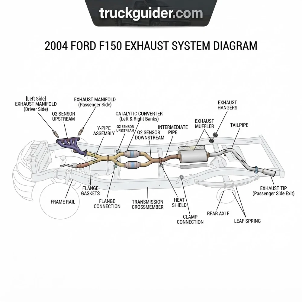
2004 Ford F150 Exhaust System Diagram: Anatomy and Components
Recommended Best Deal Products


Navigating the 2004 ford f150 exhaust system diagram requires a systematic understanding of how engine combustion byproducts travel through the chassis. Starting at the cylinder heads, the system begins with the exhaust manifolds. On the 5.4L 3V Triton V8, these cast-iron units are notoriously prone to manifold bolt shearing due to thermal expansion cycles. The manifold functions as the primary collector, transitioning the high-velocity gases into the downpipes.
Embedded within these downpipes, you will identify the upstream catalytic converters. In the 2004 layout, the system features a dual-bank configuration where each cylinder bank utilizes an individual catalyst. Precise oxygen sensor (O2) placement is critical here; the upstream sensors—positioned before the converters—monitor the air-fuel ratio for the Powertrain Control Module (PCM), while the downstream sensors verify the catalytic efficiency.
Moving rearward, the mid-pipe assembly merges these two paths into a single collector, or remains dual depending on the specific wheelbase and trim configuration (e.g., SuperCrew vs. Regular Cab). This section frequently houses the secondary catalytic converters in states requiring stricter emissions standards. The structural integrity of these pipes depends on high-quality stainless steel flanges and specialized graphite-mesh gaskets designed to withstand extreme vibration.
Further back, the system enters the muffler assembly. The 2004 OEM muffler is a multi-chambered unit designed to cancel out specific low-frequency exhaust drone common in V8 engines. Finally, the tailpipe assembly carries the processed gas past the rear axle, supported by vulcanized rubber exhaust hangers. These hangers are critical; as shown in the schematic, the failure of a single hanger can induce harmonic resonance that fatigues the pipe welds at the muffler inlet, causing premature leaks.
When replacing any component downstream of the manifolds, always apply a high-temperature nickel-based anti-seize compound to bolt threads. The 2004 F150’s exhaust hardware is subject to extreme corrosion, and failure to prep these threads often results in snapped studs during future servicing.
Exhaust System Specifications and Material Comparisons

Optimizing or repairing the exhaust requires adherence to OEM flow dynamics. Excessive backpressure caused by restricted catalytic converters can lead to a significant drop in torque, while over-sized aftermarket piping can negatively impact low-end scavenging. The following table provides the technical parameters for common 5.4L engine configurations.
| Specification Category | OEM Standard | Performance Variance |
|---|---|---|
| Pipe Diameter (Main) | 2.5 inch | 2.75 – 3.0 inch |
| Flange Torque Spec | 35-40 ft-lbs | Varies by hardware |
| Catalytic Material | Ceramic Monolith | Metallic Substrate |
| O2 Sensor Voltage (Target) | 0.1V – 0.9V | Steady state bias |
Material selection dictates the longevity of your repair. OEM pipes are typically aluminized steel, which is cost-effective but prone to surface rust within 5-7 years in salt-belt environments. For a permanent fix, upgrading to 409 or 304 stainless steel is recommended. While 409 stainless may develop surface oxidation, it does not suffer from structural decay like carbon steel.
The 5.4L Triton V8 relies on precise backpressure to maintain low-RPM scavenging. Installing a “straight-through” muffler or deleting the resonators may produce a desirable aggressive tone, but often introduces an intrusive 1800-2200 RPM drone. If you are modifying the system, ensure the internal volume of the mufflers matches the pulse frequency of the 5.4L cylinder firing order to mitigate cabin resonance.
For oxygen sensor replacements, use only NTK or Motorcraft OEM-equivalent sensors. The PCM logic in the 2004 F150 is highly sensitive to the switching impedance of aftermarket universal sensors, which often trigger false P0420 or P0430 catalytic converter efficiency codes.

Audible — Listen Free for 30 Days
One free credit a month and thousands of titles included.
Listen Free for 30 DaysHow to Replace 2004 Ford F150 Exhaust System Components
Recommended Best Deal Products


Performing a comprehensive overhaul of the exhaust system requires specific safety protocols and a logical sequence of operations. Use a lift if possible, as the layout of the 2004 ford f150 exhaust system diagram is difficult to access on jack stands due to the length of the mid-pipe assembly.
1. Preparation and Penetration: Soak all exhaust flange bolts and O2 sensor bungs with a high-quality penetrating oil 24 hours prior to work. Do not attempt removal without this step, as manifold studs on the 2004 F150 are notorious for snapping flush with the cylinder head.
2. Electrical Disconnection: Disconnect all four O2 sensors. When removing the sensors, use a specialized 7/8-inch crow’s foot wrench to prevent rounding the hex head. Label each sensor position (upstream/downstream, left/right) to avoid PCM mapping errors upon reinstallation.
3. Support and Lowering: Use two adjustable jack stands to support the muffler and mid-pipe. Loosen the hardware starting from the tailpipe and moving toward the manifolds. Removing the hanger rods from the rubber insulators is easiest with a dedicated exhaust hanger removal tool or a silicone lubricant spray.
4. Manifold Removal: If replacing the exhaust manifold gaskets, work from the center out. If a stud breaks, use a right-angle drill with a left-handed cobalt bit to extract the remainder. Always install new, high-grade studs and copper-coated locking nuts.
5. Installation Sequence: Always install components in reverse order. Ensure the new gaskets are seated correctly before tightening any fasteners. Torque all flanges to 35-40 ft-lbs in a circular pattern to ensure an even seal. Before starting the engine, clean the O2 sensors of any penetrating oil residue, as chemicals can contaminate the ceramic element.
Never use an impact wrench on rusty exhaust studs. The high-speed torque pulse is almost certain to snap the stud. Utilize hand tools with consistent, slow pressure to feel for binding. If the stud binds, reverse pressure and re-soak with penetrating oil.
Troubleshooting 2004 Ford F150 Exhaust System Diagram Failures
The diagnostic process relies on mapping symptoms to specific zones in the 2004 ford f150 exhaust system diagram. Many owners misidentify a simple exhaust leak for an internal engine issue, such as a lifter tick or a valve train problem.
Manifold Ticking Sound: This is the most common failure point. A ticking noise present during cold startup that disappears as the engine warms is indicative of a broken manifold stud or a failed gasket. As the metal expands, the gap closes, sealing the leak temporarily. Inspect the area surrounding the cylinder head ports for soot deposits—these are tell-tale signs of gas escaping under pressure.
Exhaust Drone and Vibration: If you experience significant cabin vibration at cruising speeds, check the rear resonators and the tailpipe hangers. A broken hanger allows the exhaust system to contact the frame or heat shield, transferring harmonic vibrations directly into the chassis.
Catalytic Efficiency Codes (P0420/P0430): When the PCM identifies a discrepancy between the upstream and downstream O2 sensor readings, it flags a catalyst failure. Before replacing the converters, verify there are no leaks in the piping between the two sensors. Even a pinhole leak can introduce oxygen into the exhaust stream, skewing the downstream sensor data and triggering a false catalyst code.
Heat Shield Rattling: A metallic, tinny sound during acceleration often points to a rusted heat shield clamp. Use large stainless steel worm-gear hose clamps to secure loose shields rather than attempting to weld them, as the localized heat from welding can weaken the thin pipe material.
* Power Loss and High EGT: If the vehicle feels lethargic and the exhaust note is muffled, check for a collapsed inner core within the catalytic converter. This effectively creates a “cork” in the system. Verify this by measuring the temperature differential across the converter with an infrared thermometer; a faulty unit will typically show a temperature decrease or an abnormally high spike compared to the intake pipe.
2004 Ford F150 Exhaust System Diagram Questions Answered
Recommended Best Deal Products


Can I install a 2004 exhaust system on a 2005+ F150?
While the general structure is similar, the 2005+ models often feature different O2 sensor bung locations and varying pipe hanger lengths. It is recommended to use the part specific to your build date to ensure proper PCM clearance and sensor feedback loops.
Why is there an exhaust leak at the manifold even after gasket replacement?
This usually occurs because the manifold surface itself has warped due to extreme heat cycles. A new gasket cannot bridge the gap created by a warped flange. You must ensure the manifold face is trued on a milling machine or replaced with a new, precision-surfaced manifold.
Does changing the muffler affect my truck’s fuel economy?
Modifying the system to reduce backpressure slightly can improve engine breathing; however, it will not significantly change fuel economy unless you alter the air-fuel ratio map through custom tuning. The PCM is designed to adjust within set parameters, and an aftermarket muffler alone rarely causes a lean condition.
Audible Premium Plus — Annual Membership
12 audiobook credits up front, plus the full Audible catalogue.
See Annual PlansHow do I identify which bank is triggering the O2 sensor code?
Bank 1 is on the passenger side (closest to the #1 cylinder), and Bank 2 is on the driver’s side. The diagram confirms this orientation; P0420 relates to the passenger side, while P0430 refers to the driver’s side.
What is the benefit of replacing the stock manifolds with headers?
Shorty headers offer a minor performance gain and are usually 50-state legal if they retain the factory catalyst locations. Long-tube headers provide superior flow but will require moving the catalytic converters, which necessitates a custom tune to prevent persistent Check Engine lights and potential emissions non-compliance.
Step-by-Step Guide to Understanding the 2004 Ford F150 Exhaust System Diagram
Identify – Inspect the engine bay and underside to confirm the current exhaust configuration versus the factory diagram.
Locate – Find all flange connections and rubber hangers using the diagram as a visual roadmap.
Reference – Cross-check the diagram during disassembly to ensure all sensors and vacuum lines are disconnected safely.
Connect/Route – Align the new components according to the diagram specs, ensuring the structure clears the drive shaft and fuel tank.
Verify – Perform a leak test by running the engine and checking for escaping gases or rattle noises at joint locations.
Troubleshoot – If exhaust smells or loud ticks persist, revisit the diagram to confirm all gaskets were seated correctly at the manifold flange.
![Ram 1500 Resonator Delete: Sound, Drone & MDS Impacts [2026]](https://truckguider.com/wp-content/uploads/2026/03/ram-1500-resonator-delete-featured.webp)
![P0420 Dodge Caravan: Diagnostic Guide & Repair Costs [2026]](https://truckguider.com/wp-content/uploads/2026/03/p0420-dodge-caravan-featured-768x403.webp)
![5.7 Hemi Exhaust Manifold Upgrade [2026]](https://truckguider.com/wp-content/uploads/2026/03/featured-5f91c218-768x768.webp)