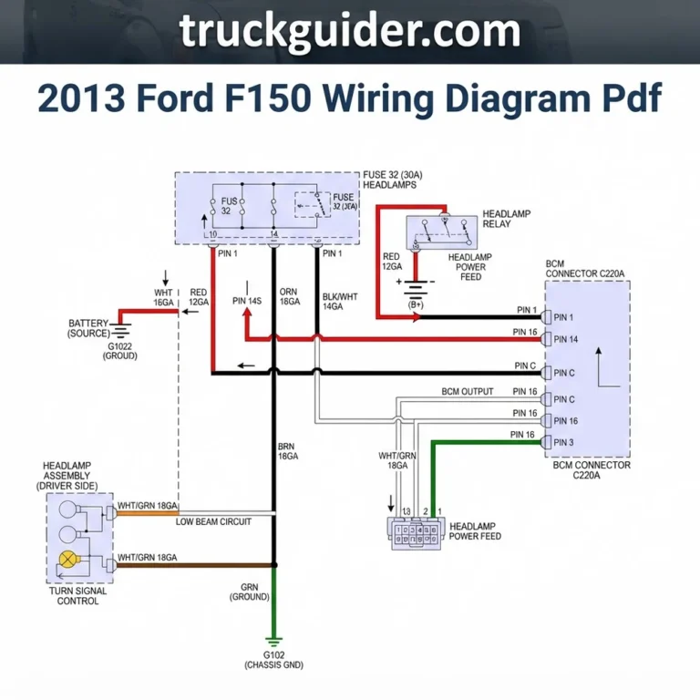
2013 Chevy Silverado Radio Wiring Diagram: Installation Setup 2026

The 2013 Chevy Silverado radio uses a factory harness where the constant 12V hot wire is typically yellow and the accessory/switched wire is often red or controlled via the vehicle’s data bus (CAN-bus). Ground wire is black. Use a multimeter to verify 12.6V before finalizing connections to prevent module damage.
📌 Key Takeaways
- The 2013 Silverado utilizes a GMLAN data bus system, meaning a specialized radio interface module is required for switched power.
- Always verify the ground wire connection point at the chassis to ensure a solid path, preventing speaker ground loop noise.
- Use 18-gauge automotive-grade primary wire for all signal connections and 16-gauge for power/ground circuits.
- Mixing up speaker polarity (+/-) will cause phase cancellation, leading to a weak, thin sound output from the factory speakers.
- Seek professional help if the vehicle’s Retained Accessory Power (RAP) features fail after installation, as this indicates a module communication error.

Upgrading the audio system in a 2013 Chevy Silverado requires a precise understanding of the vehicle’s electrical architecture. Unlike older analog systems, the 2013 model utilizes a complex GM LAN data bus, which manages everything from steering wheel controls to audible safety chimes. Attempting to bypass these protocols without a proper 2013 chevy silverado radio wiring diagram can lead to permanent damage to the vehicle’s body control module (BCM). This guide provides the technical specifications, wire color codes, and installation protocols necessary to successfully integrate an aftermarket head unit while maintaining factory system integrity and preventing electrical shorts or diagnostic trouble codes.


For a visual reference, consult the master 2013 Chevy Silverado radio wiring diagram provided in your vehicle service manual. Always verify your specific trim level, as Bose-equipped models utilize different amplifier turn-on signals compared to standard non-amplified setups.
2013 Chevy Silverado Radio Wiring Diagram and Harness Pinout
Identifying the correct wire color code within the factory harness is the most critical stage of the installation. In the 2013 Silverado, the factory radio connector is a 24-pin assembly. Because the radio communicates via the GM LAN data bus, there is no traditional switched 12V ignition wire in the main radio harness. Instead, the radio receives a “turn-on” signal via data commands from the BCM. You must use a dedicated wiring interface to translate this data into a usable switched voltage for your aftermarket head unit.
The table below outlines the standard wire color code and function for the 24-pin factory connector found in most 2013 Silverado models. Please note that wire gauge varies by function; power and ground wires generally utilize a 16-gauge or 18-gauge conductor, while data lines are typically smaller, 22-gauge conductors.
| Function | Wire Color | Technical Specification |
|---|---|---|
| Constant 12V Power Wire | Red/White | Battery (+) Feed |
| Ground Wire | Black | Chassis Ground |
| Illumination | Gray | Dimmer Control (PWM) |
| Amplifier Trigger | Blue/White | Remote Turn-on (Bose Only) |
| Left Front (+) | Tan | Speaker Level |
| Left Front (-) | Gray/Black | Speaker Level |
| Right Front (+) | Light Green | Speaker Level |
| Right Front (-) | Dark Green/Black | Speaker Level |
Do not attempt to tap into the GM LAN data wire (typically dark green or yellow/black) to provide a constant or switched power source. Connecting an external device to this bus can corrupt the vehicle’s serial data communication, leading to non-starting conditions or instrument cluster failure.
How to Integrate the 2013 Chevy Silverado Radio Wiring Diagram
Installing an aftermarket head unit in a 2013 Silverado requires a logic-based approach to ensure that the new equipment communicates properly with the factory GM LAN data bus. Simply splicing wires is insufficient; you must employ a dedicated data interface module. Follow this sequence to maintain system functionality.
1. Verify Power Supply and Grounding: Before connecting any aftermarket hardware, use a digital multimeter to verify the constant 12V power wire and chassis ground wire at the factory harness. The Red/White wire should show a steady 12.6V–14.4V regardless of ignition position. If the voltage reading is unstable, check the fuse block in the passenger-side kick panel.
2. Select the Data Bus Interface Module: Ensure you have a GM-compatible interface module (such as the PAC RP5-GM11 or equivalent). This module acts as a translator between the aftermarket radio and the vehicle’s CAN-bus. Without this, the radio will not recognize when the key is turned to the “On” or “Accessory” position.
3. Wire Configuration: Solder all connections between the aftermarket wiring harness and the interface module harness. Use high-quality heat-shrink tubing to seal every connection. Avoid using wire nuts or crimp-on connectors if possible, as vibration in a truck environment can cause these to loosen over time. Ensure the gauge of your patch wires matches the factory harness (typically 18-gauge) to prevent heat buildup.


4. Steering Wheel Control (SWC) Programming: If your truck is equipped with steering wheel controls, connect the dedicated SWC output wire (usually labeled as such on your head unit’s harness) to the interface module. The interface module will need to be programmed according to the specific manufacturer’s instructions, often involving a series of LED flash codes to “learn” the Silverado’s button resistance values.
5. Final Interface Test: Before fully reassembling the dashboard, connect the interface module to the vehicle harness and test the ignition-controlled power. The radio should power on only when the key is in the accessory or on position. If the radio stays on when the key is removed, the data interface is likely incorrectly configured or the GM LAN connection is faulty.
Always use 18 AWG stranded copper wire for radio harness extensions. Solid core wire is prone to fatigue failure in high-vibration automotive applications.
Troubleshooting 2013 Chevy Silverado Radio Wiring Diagram Errors
Even with a perfect diagram, electrical gremlins can occur during complex installations. Identifying these issues early is key to preventing long-term damage to the vehicle’s sensitive electronics.
Loss of Chime Functionality: If you have installed an aftermarket unit and no longer hear safety chimes (door open, parking sensor alerts), the issue is almost certainly with your interface module. The 2013 Silverado’s chime system is generated through the data bus and processed by the factory radio. A proper interface module includes a small auxiliary speaker to reproduce these sounds. Ensure this speaker is plugged in and not obstructed during reassembly.
Bose System Clipping or Distortion: If your vehicle is equipped with the factory Bose sound system, you must feed the aftermarket radio’s low-level signal (RCA outputs) into the interface module, not the speaker-level wires. Using speaker-level signals into the Bose amplifier will cause extreme distortion and premature hardware failure. If you are experiencing “clipping,” verify that the blue/white amplifier trigger wire is correctly pinned to provide a 12V signal to the Bose amp.
No Power/Memory Reset: If the radio loses all settings when the engine is turned off, verify the constant 12V power wire. In many cases, the constant power feed is wired into a circuit that cuts out during the engine cranking phase, causing the radio’s memory to reset. Ensure your source wire is a true constant 12V feed that remains active during the starter motor’s engagement.
CAN-bus Noise or Interference: If you notice a whining sound that changes pitch with engine RPM (alternator whine), it is likely a ground loop issue. Ensure your ground wire is connected directly to a clean, paint-free metal chassis point. Do not use the factory radio’s thin black ground wire if you have added external amplifiers or high-power aftermarket equipment; run a dedicated, heavier-gauge ground to the chassis.
* Voltage Dips: If the radio shuts off randomly while driving, use a multimeter to monitor the voltage at the harness under load. A significant voltage drop (below 10.5V) indicates a poor connection at the fuse block or a failing alternator, rather than a radio wiring error.
2013 Chevy Silverado Radio Wiring Diagram Questions Answered
How do I identify the factory amplifier trigger wire in a Bose-equipped Silverado?
The factory amplifier trigger wire is typically found in the main 24-pin harness, colored blue or blue/white. It requires a 12V signal to wake up the amplifier. If your radio lacks a dedicated amp-turn-on output, you may need to use a switched power source, provided it does not exceed the draw limits defined by the vehicle’s electrical schematic.
Is the GM LAN data bus wire sensitive to interference?
Yes, the GM LAN data bus is highly sensitive to resistance and electrical noise. Never splice, tap, or route power wires parallel to the data lines for long distances. Any interruption in this communication path will result in “No Data” messages on the Driver Information Center and could disable the radio’s ability to communicate with the vehicle’s computer.


Why does my radio stay on after I remove the key?
This is a classic sign of an improperly wired ignition sense wire. Because the 2013 Silverado does not provide a traditional 12V ignition wire, the interface module must detect the “key-off” command via the data bus. If the interface module is not configured correctly or is of a low-quality, it will not detect the signal to cut power, resulting in a parasitic battery drain.
Can I wire the speakers directly to the head unit if I have a factory amp?
Generally, no. If you have the factory Bose system, the speakers are wired to the amplifier, not the radio. If you attempt to bypass the amplifier and run wires directly from the head unit to the speakers, you will be required to run entirely new wiring throughout the vehicle, as the factory speaker wires are physically terminated at the Bose amplifier location rather than the dash.
What is the purpose of the illumination wire in the harness?
The illumination wire (typically gray) is a Pulse Width Modulation (PWM) signal, not a standard 12V on/off wire. It tells the radio to dim the display when the headlights are activated. If you connect this to a standard 12V constant source, you risk damaging the radio’s internal display controller. Always use an interface module that features a specific PWM-to-12V dimming converter.
Step-by-Step Guide to Understanding the 2013 Chevy Silverado Radio Wiring Diagram
Identify – Locate the factory radio harness and confirm your vehicle’s specific audio configuration (Bose vs. non-Bose).
Locate – Disconnect the negative battery terminal to prevent short-circuits during the installation process.
Reference – Use the wire color code chart to match your aftermarket harness wires to the factory color designations.
Connect/Route – Solder all connections or use high-quality crimp connectors, ensuring the hot wire and ground wire are securely fastened.
Verify – Reconnect the battery, turn on the ignition, and use a multimeter to check voltage levels at the radio plug.
Troubleshoot – Test audio output for all speakers and ensure the unit shuts down when the key is removed to verify the interface works.
2013 Chevy Silverado Radio Wiring Diagram: Frequently Asked Questions
What wire color is constant 12V power on 2013 chevy silverado radio wiring diagram?
The constant 12V battery source on a 2013 Chevy Silverado is identified by a yellow wire. This wire provides continuous power to maintain clock settings and radio presets. Always test this wire with a multimeter while the ignition is off to confirm it carries a steady 12-volt charge.


What do the pin numbers mean on 2013 chevy silverado radio wiring diagram?
Pin numbers correspond to specific slots within the factory radio harness connector. These positions dictate the exact function of each circuit, such as speaker outputs, illumination, and data signals. Referencing the pinout map is critical to avoid shorting the vehicle’s Body Control Module (BCM) during an aftermarket radio install.
How many wires does 2013 chevy silverado radio wiring diagram have?
A standard 2013 Chevy Silverado radio harness contains approximately 16 to 24 pins, depending on whether the truck features a base audio system, Bose premium sound, or factory navigation. The wiring includes dedicated pairs for four speakers, power, ground, and data communication lines for steering wheel controls.
What are common wiring mistakes with 2013 chevy silverado radio wiring diagram?
The most common mistake is hard-wiring the switched power source instead of using a CAN-bus interface. Because the 2013 Silverado uses digital data to turn the radio on, skipping the interface module will prevent the radio from powering up or cause it to drain the battery when the truck is off.
Do I need a brake controller for 2013 chevy silverado radio wiring diagram?
A brake controller is an entirely separate electrical system and is not required for radio installation. However, both systems share the vehicle’s fuse panel. Ensure you do not accidentally tap into brake controller wiring while routing audio cables, as this could lead to critical towing safety system malfunctions.
What gauge wire does 2013 chevy silverado radio wiring diagram require?
For basic radio connections, use 18-gauge wire to match the factory harness thickness. If you are installing an external amplifier that requires higher current, you must upgrade to 4-gauge or 8-gauge power wire, properly fused at the battery terminal, to prevent overheating or potential electrical fire hazards.


![2013 Ram 1500 Transmission Guide: Complete Specs Guide [2026]](https://truckguider.com/wp-content/uploads/2026/03/2013-ram-1500-transmission-featured.webp)