GM 5.3L L84 Sensor Location Diagram: Silverado & Sierra 2019–2026

The 5.3 L84 sensor location diagram for Chevrolet Silverado 1500 and GMC Sierra 1500 trucks places the camshaft position sensor at the front timing cover, the crankshaft position sensor behind the starter, and the engine oil pressure sensor on the left rear side near the oil-filter and cooler-line area. Other sensors are spread across the intake, cylinder block, cooling system, and exhaust.
This guide identifies those locations by their General Motors component IDs. It focuses on 2019–2026 L84-equipped trucks, with the 2026 Silverado service locator as the primary reference. Confirm your exact model year and engine RPO before using a diagram to identify a connector or order a part.



Which GM Trucks Use the L84 5.3L Engine


The L84 is GM’s longitudinal 5.3L Gen V EcoTec3 V8 with direct injection, variable valve timing, and Dynamic Fuel Management (DFM) capability. It is not the earlier L83 or L82, even though all three displace 5.3 liters. GM describes the engine architecture in its official L84 engine specifications.
For this location guide, the main applications are 2019–2026 Chevrolet Silverado 1500 and GMC Sierra 1500 trucks equipped with RPO L84. GM also used the L84 in certain Tahoe, Suburban, and Yukon configurations. A model name or engine displacement alone does not establish which V8 is installed.
Check the vehicle’s build information, RPO listing, or VIN-specific GM service record. For output ratings, cylinder-deactivation details, and engine-family comparisons, see our GM 5.3L L84 engine specifications.
How to Read the 5.3 L84 Sensor Location Diagram


Start with the engine’s orientation, not the appearance of an electrical connector. Front means the radiator and accessory-drive end; rear means the transmission and firewall end. On U.S. left-hand-drive trucks, left is the driver’s side and right is the passenger’s side. A photo taken while standing in front of the grille reverses those sides from the viewer’s perspective.


GM’s 2026 Silverado Electrical Body Builder Manual provides the component illustrations under Electrical Component Locator and Harness Routing Views, especially pages 8-833 through 8-837.
| Area to Inspect | GM Component ID | Sensor or Switch | Fixed Landmark |
|---|---|---|---|
| Front of engine | B23 | Camshaft position | Timing cover, above crankshaft balancer |
| Front of engine | B34 | Engine coolant temperature | Water pump |
| Front intake | B74 | Manifold absolute pressure (MAP) | Intake manifold near throttle body |
| Left-front engine bay | B75 | Mass airflow (MAF) | Air-cleaner lid |
| Rear upper engine | B47B | Fuel rail pressure | Rear of Bank 1 fuel rail |
| Left rear engine | B37B | Engine oil pressure | Above oil-filter area, near oil-cooler lines |
| Left rear engine block | B68A | Knock sensor 1 | Below exhaust manifold, behind shield |
| Right rear engine block | B26 | Crankshaft position | Behind starter motor |
| Right rear engine block | B68B | Knock sensor 2 | Above starter motor |
| Right lower engine | B35 | Engine oil level indicator switch | Right side of oil pan |
Use the GM identifiers before matching connector shapes. A location table can identify the mounting region, but a connector end view and removal procedure must come from the service information for your exact truck.
Where Are the Front and Intake L84 Sensors


The front of the L84 has several useful landmarks: the crankshaft balancer, timing cover, water pump, electronic throttle body, and air-cleaner assembly. Identify these larger parts before looking for the smaller sensor housings.


Camshaft Position Sensor B23


The B23 camshaft position sensor mounts in the front timing-chain-cover area above the left side of the crankshaft harmonic balancer. Locate the balancer at the lower front of the engine, then compare the timing-cover area with GM’s front component view.
The nearby Q6 camshaft position actuator solenoid valve is a separate part. A sensor-location diagram that points to Q6 and labels it B23 is incorrect. Inspect the matching component ID before unplugging either one.
Coolant Temperature Sensor B34
The B34 engine coolant temperature sensor is mounted to the water pump near the front center of the L84. Follow the cooling-system hardware toward the pump rather than searching the rear cylinder heads as you might on an older 5.3L configuration.
Let the engine cool before inspecting this area; never loosen a cap or connection on a hot, pressurized cooling system.
MAP Sensor B74
The B74 manifold absolute pressure sensor is fitted to the intake manifold near the electronic throttle body at the front-center intake area. The MAP sensor measures manifold pressure, so it should not be confused with the airflow sensor at the air-cleaner housing.


Look for the throttle-body junction first and identify B74 using the intake-side service view. The evaporative-emissions purge solenoid is another electrical component in the vicinity, but it has a different job and GM identifier.
Mass Airflow Sensor B75


The B75 mass airflow sensor is in the left-front engine compartment at the air-cleaner lid. Follow the intake tract from the filter housing toward the throttle body.
Other model-year documents may identify additional intake-air sensing functions differently, so use your truck’s wiring information rather than assuming every intake-air sensor is a separate plug-in component.
Fuel Rail Pressure Sensor B47B
The B47B fuel rail pressure sensor is at the rear of the Bank 1 fuel rail, near the back of the engine. Bank 1 is the cylinder bank containing cylinder 1, on the driver’s side of a conventional U.S. L84 truck installation.
High-pressure fuel may remain in the system after shutdown. Identify the component visually, but do not loosen a fuel-rail fitting or remove B47B without the GM pressure-release procedure.
Where Are the Rear and Block Side L84 Sensors


The starter and oil-filter area are the most useful reference points for the harder-to-see L84 sensors. These locations are not all visible in a single overhead engine-bay photograph.
Crankshaft Position Sensor B26
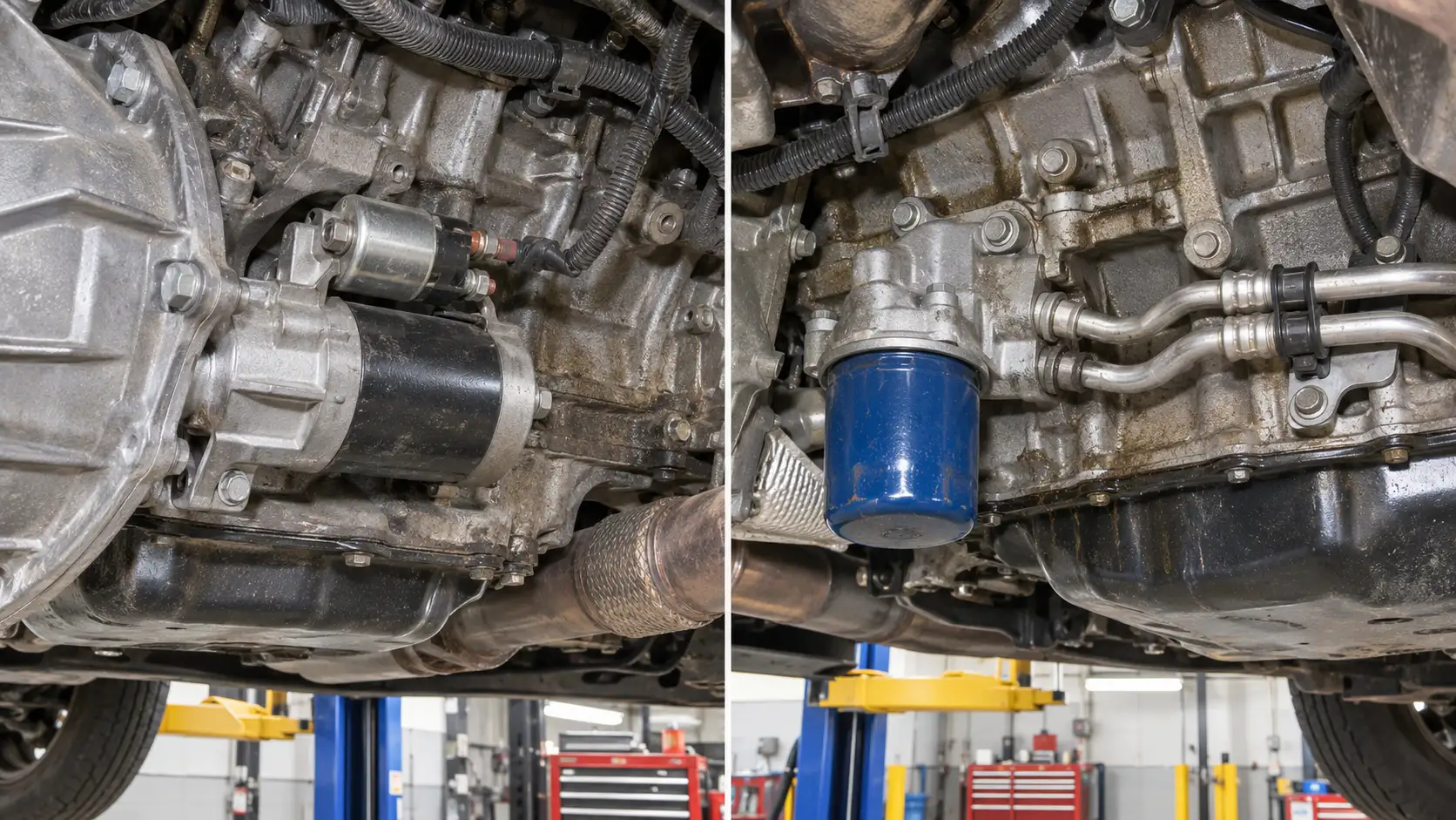
The B26 crankshaft position sensor is installed on the right rear side of the engine block, behind the starter motor. Identify the starter first. Then use the factory right-side locator to distinguish the crank sensor’s mounting point from starter wiring, transmission connections, and nearby block hardware.
A basic location check does not require removing the starter. If disassembly is necessary, follow the vehicle-specific procedure and disconnect the battery as instructed.
Engine Oil Pressure Sensor B37B
The B37B engine oil pressure sensor is on the left rear side of the L84, above the oil-filter area and associated with the oil-cooler-line mounting region. It is not the traditional top-rear oil-pressure location shown in many older Vortec diagrams.
Use the oil-filter and cooler-line hardware as landmarks, then compare the left-side GM component view. The oil-pressure sensor and an oil-pressure control solenoid are not interchangeable names for the same component. A dashboard warning also does not prove B37B has failed.
Knock Sensor 1 B68A


The B68A knock sensor 1 is mounted to the left rear engine block, below the exhaust manifold and behind a knock-sensor shield. It is not visible as a standalone sensor on the top of the intake manifold.
Find the driver-side exhaust manifold and use the block-side service illustration to locate the shielded mounting area. Do not touch or reach behind hot exhaust parts.
Knock Sensor 2 B68B
The B68B knock sensor 2 mounts to the right rear engine block above the starter. It is near B26, but GM identifies the two components separately. The crank sensor is behind the starter; knock sensor 2 is above it.
Use a work light and the right-side locator to distinguish the two mounting regions. Never work beneath a truck supported only by a jack. If the view is blocked, use the correct service procedure instead of pulling on an unidentified connector.
Engine Oil Level Indicator Switch B35
The B35 engine oil level indicator switch is installed on the right side of the oil pan. It is a different device from the B37B oil-pressure sensor. The two report different conditions and use different component IDs.
Do not diagnose an oil-pressure fault by substituting the oil-level switch or its connector.
Where Are L84 Oxygen Sensors on Silverado and Sierra
The L84 exhaust system has upstream and downstream oxygen-sensor positions for each cylinder bank. Sensor 1 means upstream of the catalytic converter, while Sensor 2 means downstream. Cylinder 1 is on the driver-side bank of a conventional U.S. Silverado or Sierra installation.
| GM ID | Scan-Tool Designation | Exhaust Position |
|---|---|---|
| B52C | Bank 1 Sensor 1 | Driver-side bank, upstream |
| B52D | Bank 1 Sensor 2 | Driver-side bank, downstream |
| B52E | Bank 2 Sensor 1 | Passenger-side bank, upstream |
| B52F | Bank 2 Sensor 2 | Passenger-side bank, downstream |
GM’s electrical manual identifies these component IDs and shows that upstream oxygen-sensor connectors can differ with emissions configurations. Do not order by connector pin count or color without checking the VIN and applicable option codes.
For example, a code referring to Bank 2 Sensor 2 identifies the downstream sensor on Bank 2. It does not mean the second oxygen sensor you encounter while looking under the truck.
How to Match the Correct L84 Sensor Before Removal
A sensor’s location tells you where to inspect; it does not tell you whether the sensor needs replacement. This four-step process prevents common identification errors.
- Confirm L84 and the model year. Check the RPO or VIN-specific build record. Do not treat every GM 5.3L V8 as an L84.
- Orient the engine. Establish the radiator end, transmission end, and actual vehicle left and right. Do not use photo-left and photo-right as substitutes.
- Match the GM ID and landmark. Use B23 for the cam sensor, B26 for the crank sensor, or the appropriate ID from the location table. Identify the adjacent larger component before looking for the plug.
- Check the exact connector and safe access method. Compare the service connector view, inspect for damage, and read the factory procedure before removing shields, starters, fuel lines, or exhaust components.
The 2022 Silverado 1500 LTD electrical manual also includes L84/L87 component-location illustrations. Compare the matching model-year reference when working across the 2019–2026 range; a later diagram does not guarantee identical brackets, connectors, or harness routing on every truck.
How L84 Sensor Locations Differ From Older 5.3 Engines
The L84 belongs to the Gen V EcoTec3 family. Older Gen III and Gen IV Vortec engines share the 5.3L displacement but not a universal sensor layout. On common Gen III Vortec engines, the cam sensor is toward the rear and knock sensors sit beneath the intake in the valley. The L84 instead uses a front cam sensor and block-side knock sensors.
Our 5.3 Vortec engine diagram covers the older layouts in detail. Use it for an LM7, LC9, or another engine it specifically describes, not as an L84 component locator.
Engine generation matters when choosing replacement components as well as diagrams. Our 5.3 Vortec interchangeability guide explains the generation differences, but the final parts decision must still be made with the exact VIN and current GM parts catalog.
When L84 Sensor Codes Need More Testing
A diagnostic trouble code identifies a system or circuit needing investigation. It does not automatically authorize replacing the sensor named in the description. Damaged wiring, connector problems, pressure conditions, and engine faults may produce similar symptoms.
For example, GM Service Bulletin 24-NA-173 addresses DTC P0521 on specified L84/L87 applications. The bulletin describes a possible stuck oil-pump pressure-relief valve, and directs technicians to check electrical and sensor concerns before proceeding with mechanical oil-pressure testing. Its applicability is limited to the vehicles and years listed in the bulletin.
If an oil-pressure warning appears, stop driving when safe and follow the owner’s manual’s warning instructions. Sensor identification is only the beginning of the diagnosis.
How to Find the Right L84 Sensor Safely
The 5.3 L84 sensor location diagram works best as a component-identification reference. First confirm the L84 RPO, then match the GM ID with a fixed landmark such as the timing cover, throttle body, starter, oil-filter area, or exhaust bank.
Use a front view for B23 and B34, an intake view for B74 and B75, and a side or lower-engine view for B26, B37B, and the knock sensors. If you cannot positively identify the part, do not disconnect it based on a generic 5.3L image. Consult the service view for your exact truck before ordering parts or starting removal.
5 Common Questions About L84 Sensor Locations
Where Is the Crankshaft Position Sensor on a 5.3 L84?
The B26 crankshaft position sensor is mounted at the right rear of the L84 engine block behind the starter motor. On U.S. Silverado and Sierra trucks, that means the passenger-side rear of the engine. Identify the starter and verify the block-mounted sensor using the correct service illustration.
Where Is the L84 Camshaft Position Sensor Located?


The B23 camshaft position sensor is at the front timing cover, above the left side of the crankshaft balancer. It must not be confused with the nearby Q6 camshaft position actuator solenoid. The GM component locator identifies these as separate parts.
Is the L84 Oil Pressure Sensor Behind the Intake?
No. The L84’s B37B oil-pressure sensor is on the left rear side of the engine above the oil-filter area, near the oil-cooler-line hardware. Diagrams of older 5.3L Vortec engines may show a different mounting location, so confirm that the engine RPO is L84.
Does the L84 Have the Same Sensor Locations as the L87?
GM groups several L84 and L87 locations in shared service component views, including B23, B26, B34, and the knock sensors. However, this does not establish interchangeable sensors, connectors, or brackets. Compare the related GM L87 6.2L sensor location diagram only after confirming the engine code.
How Do I Identify Bank 1 and Bank 2 Oxygen Sensors?
Bank 1 contains cylinder 1 and is the driver’s-side bank on a conventional U.S. L84 truck; Bank 2 is the passenger side. Sensor 1 is upstream of its catalytic converter and Sensor 2 is downstream. Match both the bank and sensor number before selecting a replacement oxygen sensor.