5.3L Vortec Engine Diagram: Component & Sensor Location Guide 2026

The 5.3 Vortec engine diagram helps you identify the intake manifold, throttle body, ignition coils, sensors, cylinder banks, accessory drive, and other major components on GM’s 5.3L truck V8.
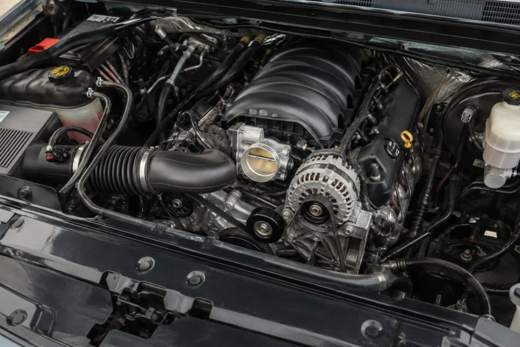
The critical detail is engine generation. The Vortec 5300 name covers several Gen III and Gen IV engines, so a sensor location that is correct for an LM7 may be wrong for an LY5, LC9, or LMG. GM’s own parts literature identifies the LM7 and L59 as 5.3L Vortec 5300 engines used extensively in trucks, SUVs, and vans.

Prime for Young Adults — 6 Months Free
Students and 18–24s get six months of Prime free, then half price.
Start 6 Months FreeUse the diagrams in this guide to identify the basic layout first. Then confirm your engine’s RPO code before ordering sensors, harnesses, or internal parts.
Use the front accessory-drive end of the engine as your orientation point. Odd-numbered cylinders are on the driver-side bank and even-numbered cylinders are on the passenger-side bank.
Firewall
Vortec
V8
Belt Drive
What Does the 5.3 Vortec Engine Diagram Show
Recommended Best Deal Products


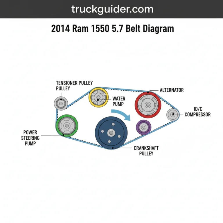
For a truck-mounted 5.3L Vortec V8, the easiest reference point is the front accessory-drive end of the engine. The crank pulley, water pump, alternator, and serpentine-belt drive sit at this end.
A labeled 5.3 Vortec engine diagram should identify these major components:
| Diagram Label | Component | Main Function | General Location |
|---|---|---|---|
| 1 | Intake manifold | Distributes intake air | Top center |
| 2 | Throttle body | Controls incoming airflow | Front of intake |
| 3 | Driver-side valve cover | Covers left-bank valvetrain | Left side |
| 4 | Passenger-side valve cover | Covers right-bank valvetrain | Right side |
| 5 | Ignition coils | Fire individual spark plugs | Along valve covers |
| 6 | Fuel rails | Supply fuel to injectors | Above intake ports |
| 7 | Fuel injectors | Meter fuel into each intake port | Along fuel rails |
| 8 | Alternator | Charges electrical system | Front accessory drive |
| 9 | Water pump | Circulates engine coolant | Front center |
| 10 | Crank pulley | Drives accessory belt | Lower front |
| 11 | Exhaust manifolds | Collect exhaust gases | Outside cylinder heads |
| 12 | Oil pan | Stores engine oil | Bottom of engine |
The exact bracket shape and accessory position can vary by vehicle. Silverado, Sierra, Tahoe, Suburban, Yukon, Avalanche, and van applications should therefore be matched to the correct model year before disassembly.
Once the visible components are identified, sensor placement becomes the more important distinction between Gen III and Gen IV engines.
Where Are the Main 5.3 Vortec Sensors Located
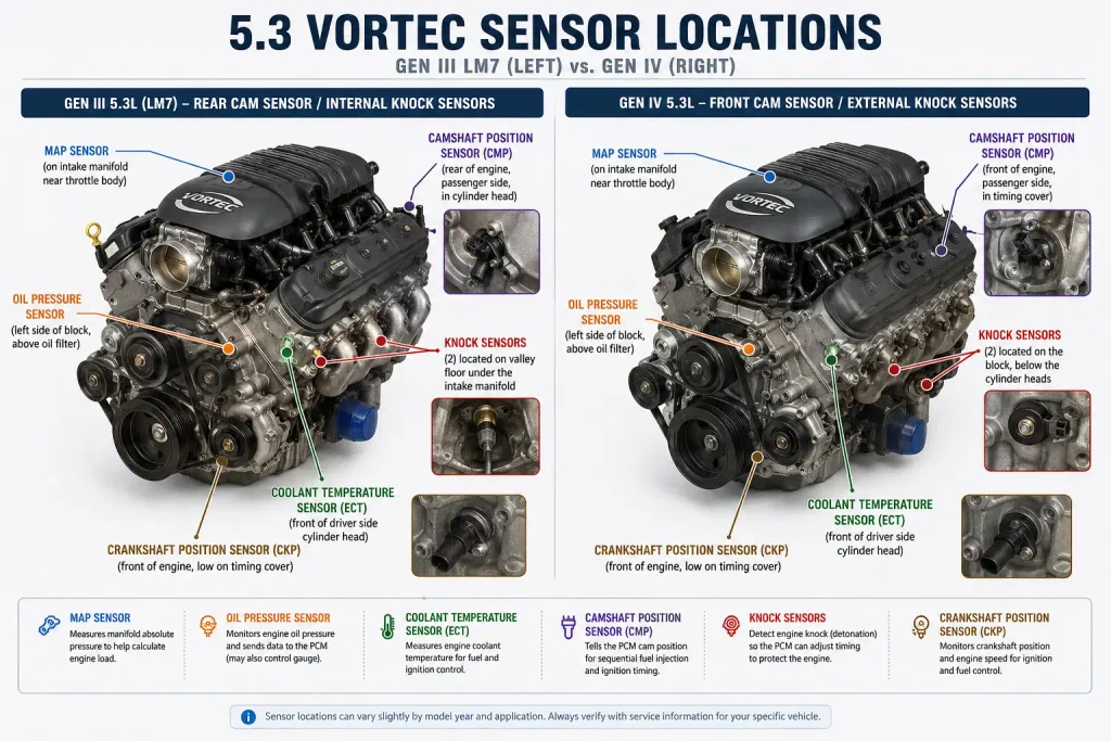
Sensor locations are not identical across every 5.3L Vortec. Gen III engines such as the LM7 use a different camshaft and knock-sensor arrangement from many Gen IV versions.
MAP Sensor Location
The MAP sensor, or Manifold Absolute Pressure sensor, measures pressure inside the intake manifold so the engine controller can calculate load.
On the 2007 Silverado 5.3L layout, GM service information places the MAP sensor on the upper intake area near the throttle body. It is visible from above without removing the intake manifold.

Audible — Listen Free for 30 Days
One free credit a month and thousands of titles included.
Listen Free for 30 DaysOil Pressure Sensor Location
On a Gen III 2004 Silverado 5.3L, the engine oil pressure sensor sits at the rear center of the engine block near the top. This makes access difficult because the sensor sits close to the firewall.
Later Gen IV layouts retain the oil-pressure sensor toward the right-rear upper engine area on common LC9 and LMG applications.
A low oil-pressure reading should not automatically be blamed on the sensor. Confirm actual oil pressure and the correct service procedure before replacing parts.
Coolant Temperature Sensor Location
The Engine Coolant Temperature sensor, or ECT sensor, reports coolant temperature to the engine controller.
On common truck V8 layouts, the ECT sensor is installed in the cylinder-head cooling passage toward the front area of the engine. GM’s later 5.3L component views place it toward the front-left side of the V8 layout.
Crankshaft Position Sensor Location
The Crankshaft Position sensor, or CKP sensor, is mounted low on the engine rather than on top.
On 2007 and 2008 Silverado 5.3L service layouts, GM places the CKP sensor on the right side of the engine near the starter area.
The sensor reads crankshaft position so the engine controller can determine engine speed, ignition timing, injection timing, and misfire information.
Audible Premium Plus — Annual Membership
12 audiobook credits up front, plus the full Audible catalogue.
See Annual PlansCamshaft Position Sensor Location
This is one of the most important Gen III versus Gen IV differences.
On Gen III 5.3L engines such as the LM7, service procedures access the camshaft position sensor from the rear portion of the engine. A 2004 Silverado service procedure groups the camshaft and oil-pressure sensor connections at the rear of the engine block.
On later Gen IV truck engines, the camshaft position sensor moved to the front cover area. GM’s 2008 Silverado component diagram identifies the CMP sensor on the left-front side of the engine.
This difference alone is enough to make many generic 5.3 Vortec sensor diagrams misleading.
Knock Sensor Location
Gen III and Gen IV layouts also differ substantially here.
Common Gen III LS-based truck engines place two knock sensors beneath the intake manifold in the engine valley. GM diagnostic information describes one sensor toward the front of the valley and the second toward the rear.
Later Gen IV truck layouts moved the sensors away from that classic under-intake arrangement. GM service information for a 2008 Silverado shows Knock Sensor 1 toward the front-left side and Knock Sensor 2 on the right side of the engine.
MAF Sensor Location
The Mass Air Flow sensor, or MAF sensor, is not mounted directly to the engine block.
It sits in the air-intake tract between the air-cleaner assembly and throttle body. GM service information instructs that the airflow-direction arrow on the sensor must point toward the engine.
These differences make the RPO code important before any sensor replacement.
How Are 5.3 Vortec Cylinders Numbered
GM numbers the cylinders on the truck 5.3L V8 with odd numbers on the left bank and even numbers on the right bank. GM service information confirms cylinders 1, 3, 5, and 7 are on the left bank, while 2, 4, 6, and 8 are on the right bank.
Viewed from the front accessory-drive end, the basic layout is:
Rear of Engine / Firewall

Driver Side            Passenger Side

7                       8
5                       6
3                       4
1                       2

Front of Engine / Belt Drive
The firing order is:
1-8-7-2-6-5-4-3
GM service specifications confirm this firing order on both earlier 5.3L truck engines and later Gen IV 5.3L applications.
| Reference | Specification |
|---|---|
| Driver-side bank | 1, 3, 5, 7 |
| Passenger-side bank | 2, 4, 6, 8 |
| Cylinder 1 | Front of driver-side bank |
| Firing order | 1-8-7-2-6-5-4-3 |
Cylinder numbering matters when diagnosing P0301 through P0308 cylinder-specific misfire codes. It also prevents you from replacing a coil, injector, or spark plug on the wrong cylinder.
If you are servicing the ignition system, also verify the correct 5.3 Vortec spark plug gap for the exact engine and model year.
How Do Gen III and Gen IV 5.3 Vortec Engines Differ
The phrase 5.3 Vortec covers more than one engine architecture. You should not buy sensors, harnesses, reluctor components, or control-system parts based only on displacement.
Gen III 5.3L engines include the LM7, L59, LM4, and L33. Engine-reference data identifies these engines with 24x crank reluctors. Common Gen IV truck variants such as the LY5, LC9, and LMG generally use the later 58x crank architecture.
| Feature | Gen III 5.3L Vortec | Gen IV 5.3L Vortec |
|---|---|---|
| Common RPOs | LM7, L59, LM4, L33 | LY5, LC9, LMG, LH6 and others |
| Common years | Late 1990s through 2007 | Mid-2000s through 2014 depending on RPO |
| Crank reference | Commonly 24x | Commonly 58x |
| Cam sensor | Rear on common Gen III engines | Front on common Gen IV layouts |
| Knock sensors | Commonly below intake in valley | Moved to block-side locations on later layouts |
| AFM | Not used on LM7, L59, LM4, L33 | Used on several Gen IV 5.3L engines |
| Block material | Iron or aluminum by RPO | Iron or aluminum by RPO |
Gen III Vortec 5300 Layout
The LM7 is the best-known Gen III 5.3L Vortec truck engine. GM Performance Parts described the LM7/L59 Vortec 5300 as a 5.3L truck, SUV, and van engine family used since 1999.
Published LS-family identification data lists the LM7 from 1999 through 2007, L59 from 2002 through 2007, LM4 from 2003 through 2005, and L33 from 2005 through 2007.
For identification work, Gen III owners should pay particular attention to the rear cam sensor and valley-mounted knock sensors.
Gen IV Vortec 5300 Layout
Common truck-oriented Gen IV engines include the LY5, LC9, LMG, and selected LH6 variants.
The LY5 was used in trucks and SUVs during the 2007 through 2009 period. LC9 and LMG production continued longer depending on application.
GM service diagrams for later 5.3L engines show the camshaft sensor toward the front and knock sensors mounted outside the Gen III valley arrangement.
Several Gen IV engines also use Active Fuel Management, or AFM. For example, GM service specifications identify AFM operation on cylinders 1, 4, 6, and 7 in LC9 and LMG applications.
The safe rule is simple: confirm the RPO before applying a Gen III or Gen IV diagram.
Where Are the 5.3 Vortec Cooling Components Located
Most major cooling-system components sit at the front of the engine.
The water pump mounts at the front-center of the block. The thermostat and radiator-hose connections are integrated into the front cooling layout, while the serpentine belt drives the water pump and other front accessories.
Typical front-drive components include:
- water pump
- crankshaft pulley
- alternator
- belt tensioner
- idler pulley
- power steering pump on applicable trucks
- A/C compressor
Cooling-system routing becomes more complicated once the radiator, heater core, bypass passages, and expansion system are included.
For that routing, use the dedicated 5.3 Vortec cooling system diagram rather than treating the general engine diagram as a coolant-flow schematic.
Which 5.3 Vortec Components Are Commonly Misidentified
Several 5.3L components sit close together or disappear beneath the intake and wiring harness.
MAP Sensor and EVAP Purge Solenoid
The MAP sensor and EVAP purge hardware can both appear near the upper intake area.
The MAP sensor measures intake-manifold pressure. The EVAP purge solenoid controls fuel-vapor flow from the evaporative-emissions system.
Use connector shape and exact intake position rather than guessing from a general engine photo.
Cam Sensor and Oil Pressure Sensor
On Gen III engines, both components are toward the rear upper engine area.
The oil-pressure sensor sits at the rear center near the top of the block. The cam sensor is also accessed from the rear on common Gen III applications.
This is a common source of confusion when viewing the engine from above.
Knock Sensor Connectors and Sensors
On Gen III engines, seeing the knock-sensor harness does not mean you are looking directly at the sensors.
The two sensors themselves sit underneath the intake manifold. Reaching them requires intake-manifold removal.
Crank Sensor and Starter Area
The crankshaft sensor sits low on the right side near the starter on common truck applications.
From above, it can be difficult or impossible to see clearly. Access is normally easier from underneath or through the right-side engine area.
Gen IV Knock Sensors
Do not search beneath the intake for Gen III-style knock sensors if your later engine uses the Gen IV layout.
GM’s 2008 Silverado component information locates one knock sensor toward the front-left area and the other on the right side of the engine.
AFM Valley Components
Some Gen IV 5.3L engines use a Valve Lifter Oil Manifold, commonly shortened to VLOM, as part of the Active Fuel Management system.
GM’s 5.3L component views specifically identify the VLOM on applicable 5.3L engines such as LC9 and LMG.
This component does not belong on a generic Gen III LM7 diagram.
How Can You Identify Your Exact 5.3 Vortec
Identifying the exact engine before ordering parts prevents many expensive mistakes.
1. Check the Model Year
Start with the truck’s model year, but do not stop there.
The transition between Gen III and Gen IV engines includes overlap. Some 5.3L engine families appeared during the same general production period.
2. Find the RPO Code
The RPO, or Regular Production Option code, identifies the installed engine configuration more accurately than displacement alone.
Common codes include:
- LM7 for a Gen III iron-block 5.3L
- L59 for the Gen III flex-fuel version
- L33 for an aluminum-block high-output truck 5.3L
- LY5 for a Gen IV iron-block truck/SUV engine
- LC9 for a Gen IV aluminum-block truck/SUV engine
- LMG for a Gen IV iron-block truck/SUV engine
Engine-reference data also shows different VIN eighth-digit identifiers for these RPOs.
3. Confirm the Engine Generation
A common LM7, L59, LM4, or L33 is Gen III.
LY5, LC9, and LMG are Gen IV configurations. Some engine families around the transition period require closer RPO-specific verification because crank and cam patterns changed during production.
4. Match the Sensor Layout
A rear-mounted cam sensor and under-intake knock sensors strongly match the common Gen III layout.
A front cam sensor and external block-side knock sensors point toward the later Gen IV architecture.
5. Match Parts to the RPO
Do not assume two 5.3L engines use interchangeable electronic components simply because their displacement is identical.
Crank reluctors, cam sensing, AFM hardware, block material, wiring, and engine-control systems can differ. The RPO should control your final parts lookup.
How Should You Use a 5.3 Vortec Engine Diagram
Use a 5.3 Vortec engine diagram as an identification and orientation reference. Start at the front accessory drive, establish the left and right cylinder banks, identify the engine RPO, then match the component or sensor to the correct generation.
Do not use one generic engine image as a replacement for an electrical schematic or factory repair procedure. Wiring, harness routing, sensor architecture, emissions equipment, and accessory brackets can change by year and application.
Once the exact engine is confirmed, you can use the diagram to locate the correct cylinder, coil, sensor, fuel injector, cooling component, or accessory without guessing.
5 Common Questions About the 5.3 Vortec Engine Diagram
Where Is Cylinder 1 on a 5.3 Vortec
Cylinder 1 is at the front of the left, or driver-side, cylinder bank in typical longitudinal GM truck installations. The left bank contains cylinders 1, 3, 5, and 7, while the right bank contains 2, 4, 6, and 8.
What Is the 5.3 Vortec Firing Order
The 5.3L GM V8 firing order is 1-8-7-2-6-5-4-3. GM service specifications show this sequence on both earlier and later 5.3L truck applications.
Where Is the Camshaft Position Sensor on a 5.3 Vortec
The location depends on generation. Common Gen III engines place the camshaft position sensor toward the rear of the engine, while later Gen IV 5.3L layouts move the sensor to the front cover area.
Where Is the Oil Pressure Sensor on a 5.3 Vortec
On common Gen III truck engines, the oil-pressure sensor is at the rear center of the engine block near the top. Later Gen IV truck layouts also position the sensor toward the rear upper engine area, although access and surrounding hardware differ.
Are All 5.3 Vortec Engine Diagrams the Same
No. Gen III engines such as the LM7 and L59 differ from Gen IV engines such as the LY5, LC9, and LMG in crank-reference systems, cam-sensor location, knock-sensor placement, and AFM hardware. Always match the diagram to the RPO code before repairing or ordering parts.
![Top Radiator Hose Hot and Bottom Cold? Causes & Fixes [2026]](https://truckguider.com/wp-content/uploads/2026/03/top-radiator-hose-hot-bottom-cold-featured.webp)

![Head Gasket Leak Oil Color: Diagnosis & Repair [2026]](https://truckguider.com/wp-content/uploads/2026/03/head-gasket-leak-oil-color-featured.webp)