6.7 Cummins Fuel Line Diagram: Understanding HPCR Layout and Component Routing
For the 6.7 Cummins owner or technician, the fuel system is the high-pressure heart of the engine, capable of generating force that dwarfs traditional mechanical systems. Navigating the complex web of supply, high-pressure, and return lines can be daunting without a clear roadmap, leading to diagnostic errors or safety risks. This comprehensive guide provides a professional-grade breakdown of the 6.7 Cummins fuel line diagram, covering everything from component locations to flow paths and troubleshooting protocols. By understanding the complete layout of the High-Pressure Common Rail (HPCR) system, you can ensure your engine remains reliable and trusted for years to come.
Anatomy of the 6.7 Cummins High-Pressure Common Rail (HPCR) System
The 6.7L Cummins, introduced midway through 2007, marked a significant departure from the mechanical and early electronic injection systems of the past. At its core, the expert design utilizes a High-Pressure Common Rail (HPCR) architecture. Unlike the older 5.9L systems that relied on mechanical timing or vp44 pumps, the HPCR system treats the fuel rail as a high-pressure accumulator. This rail maintains a constant reservoir of fuel, ready to be deployed to any of the six injectors at a moment’s notice.
One of the most professional advantages of this system is the Electronic Control Module (ECM) management. The ECM manages injection timing and duration independently of engine speed or camshaft position. This allows for multiple injection events per combustion cycle—such as pilot, main, and post-injection—which reduces engine noise and lowers emissions. However, this precision requires the system to maintain structural integrity under pressures that can reach upwards of 26,000 psi (1,800 bar).
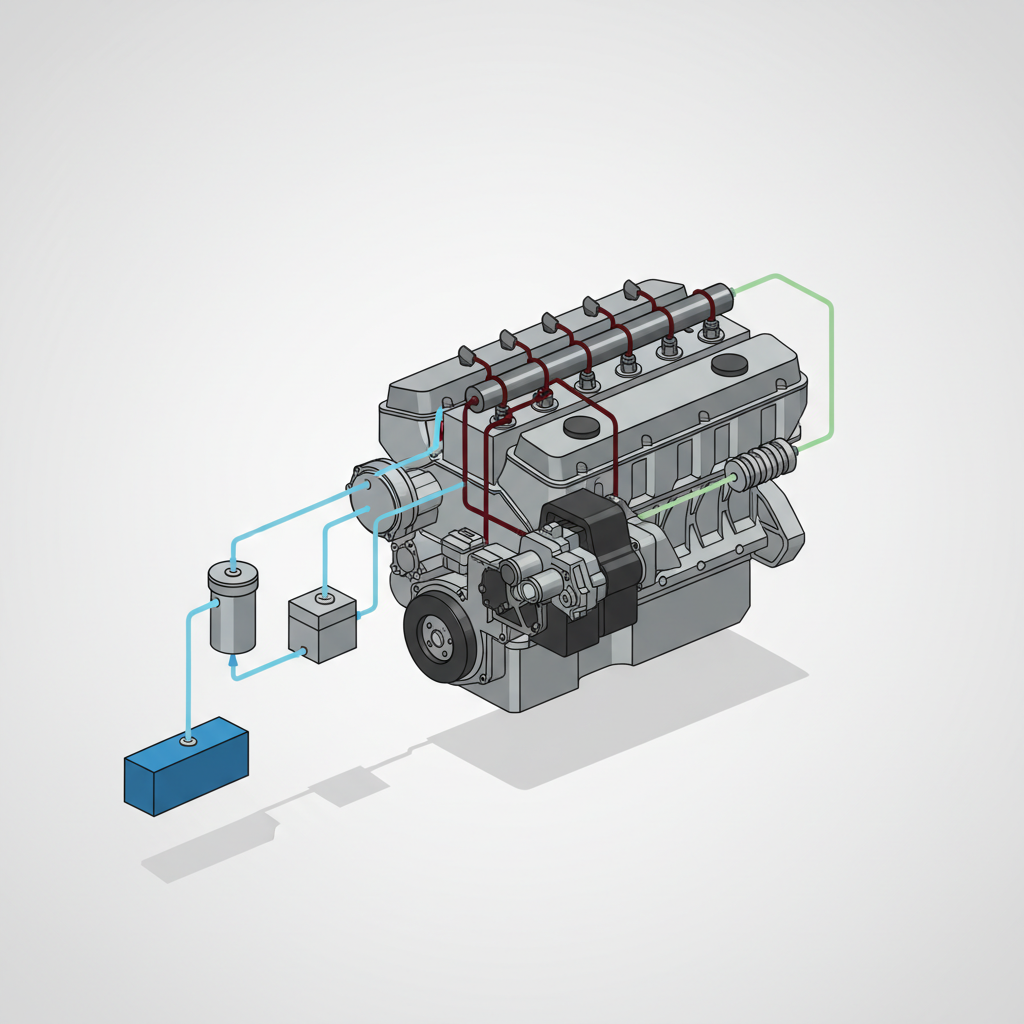
A comprehensive fuel line diagram distinguishes between two primary zones: the low-pressure supply side (suction/lift) and the high-pressure injection side. The low-pressure side handles fuel delivery and filtration, while the high-pressure side handles the actual atomization and combustion. Understanding this distinction is the first step in reliable diagnostics, according to BLANKPLACEHOLDER”>expert tips from industry leaders.
Detailed 6.7 Cummins Fuel Line Routing: From Tank to Injector
Visualizing the 6.7 Cummins fuel line diagram requires tracing the physical path fuel takes through the chassis and engine bay. While there are slight variations between a standard Ram 2500 and a Chassis Cab model—particularly in filter placement—the fundamental flow remains consistent.
The Low-Pressure Supply Circuit
The journey begins at the fuel tank, where an in-tank electric lift pump sends fuel forward. In most 2013+ models, the fuel first encounters a rear-mounted primary fuel filter/water separator. It then travels through a supply line to the engine-mounted secondary filter. This dual-stage filtration is trusted to protect the sensitive high-pressure pump from contaminants. Research indicates that even microscopic debris can cause catastrophic failure in an HPCR system.
The High-Pressure Transition
From the secondary filter, a low-pressure rubber or braided line carries fuel to the high-pressure pump—the Bosch CP3 (found on 2007.5–2018 models) or the CP4.2 (found on 2019+ models). This pump is the “heavy lifter,” converting low-pressure supply into the extreme pressures required by the rail. A heavy-duty steel discharge line connects the pump to the fuel rail. The fuel rail itself acts as a buffer, using its volume to dampen pressure pulsations created by the pump’s strokes.
The Return Circuit: The Path Back
Not all fuel sent to the rail is consumed. The 6.7 Cummins uses a complex return circuit. Unused fuel from the injectors (used for cooling and lubrication) and any excess fuel bled off by the Pressure Relief Valve (PRV) is collected and sent back to the tank. This return flow is vital; if the return lines are kinked or restricted, the resulting backpressure can lead to erratic engine behavior or blown injector seals. For the exact layout, many technicians consult the BLANK
PLACEHOLDER”>official guide for component locations.By The Numbers
Max PSI (1800 Bar)
Filter Efficiency
Filter Change Interval
Cranking PSI Required
Identifying Critical Components in the Fuel System Diagram
A complete understanding of the fuel line diagram requires identifying the specific components that manage the flow. Each part plays a quality-critical role in maintaining engine performance.
- High-Pressure Fuel Pump (CP3/CP4): These gear-driven pumps are the core of the system. While the CP3 is legendary for its durability, the CP4.2 used in later models is more efficient but more sensitive to fuel lubrication.
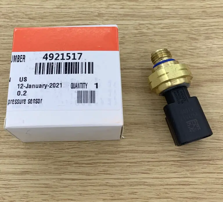
- Fuel Rail Pressure Sensor: Located typically at the end of the rail, it provides real-time data to the ECM. If this sensor fails, the engine may go into “limp mode” to prevent damage.
- Pressure Relief Valve (PRV): This is a mechanical safety valve. If the rail pressure exceeds safe limits, the PRV opens, dumping fuel into the return circuit. A common failure is a “popped” PRV that leaks fuel even at normal pressures, causing a hard-start condition.
- Fuel Injectors and Connector Tubes: The fuel enters the side of the cylinder head through a “connector tube” (or crossover tube), which presses against the injector inlet. This metal-to-metal seal must be perfectly clean to prevent leaks.
Troubleshooting Common Failures via the Fuel Line Diagram
Using the fuel line diagram as a diagnostic map is the expert way to solve “crank-no-start” or “low power” issues. One of the most frequent problems I see in the field is a cracked #4 injector line. Due to engine harmonics and vibration, the #4 line is particularly susceptible to fatigue. Identifying this leak early can prevent an engine bay fire.
Air intrusion is another “invisible” enemy. If there is a small crack or a loose fitting on the suction side (between the tank and the CP pump), the lift pump may draw in air rather than fuel. This causes the high-pressure pump to lose prime. Using the diagram, you should check every connection from the tank forward, especially the quick-connect fittings at the fuel filter housing.
If your 6.7 Cummins won’t start, use a scan tool to monitor “Desired vs. Actual” rail pressure. The ECM will not trigger the injectors until it sees at least 3,500 to 4,000 psi. If pressure is lower, use the diagram to trace the flow; the fuel is likely being bled off through a faulty PRV or a leaking injector return.
Maintenance Best Practices for Fuel System Reliability
To keep the HPCR system reliable, you must adhere to a strict maintenance schedule. The standard recommendation is to replace both fuel filters every 15,000 to 20,000 miles. However, if you frequently use “budget” fuel or operate in dusty conditions, I recommend shortening that interval to 10,000 miles.
📋
Professional Priming Procedure
Install high-quality Fleetguard or Mopar filters. Ensure seals are lubricated with clean diesel fuel to prevent “rolling” the O-ring during installation.
Turn the key to ‘Run’ and quickly bump the starter (without fully starting). This triggers the lift pump to run for ~30 seconds. Repeat 3-4 times to air-bleed the low-pressure lines.
Furthermore, the 2019-2020 CP4.2 pump recall highlighted the necessity of consistent fuel quality. Using a lubricity improver additive can provide an extra layer of protection for the high-pressure pump internals, especially when using modern Ultra-Low Sulfur Diesel (ULSD), which lacks the natural lubrication of older fuels. Consult
Safety Precautions and Professional Handling Standards
Working on a 6.7 Cummins fuel system is not like working on a gasoline engine or an older mechanical diesel. The pressures involved are high enough to be lethal. Never check for leaks by running your hand along a fuel line while the engine is running.
Diesel fuel injected into the skin at common rail pressures can cause localized tissue necrosis and systemic toxicity. Always use a piece of cardboard to search for mists. If an injection occurs, seek immediate medical attention.
Additionally, many high-pressure lines and connector tubes are designed as “one-time use” or “crush-to-seal” components. When you tighten the nut on a high-pressure line, the metal deforms slightly to create a perfect seal. Reusing these lines often results in microscopic leaks that are difficult to seal later. Finally, always wait at least 10 minutes after engine shutdown before opening any fuel circuit to allow residual rail pressure to bleed down naturally.
✅ System Pros
- Incredible fuel atomization
- Quiet, efficient operation
- Precise ECM control
- High torque at low RPM
❌ System Cons
- Extreme sensitivity to dirt
- Expensive components
- Safety risks (high PSI)
- Complex troubleshooting
The 6.7 Cummins relies on a precise HPCR system that requires an intimate understanding of fuel flow from tank to injector. Proper identification of components like the CP3/CP4 pump and the fuel rail is essential for accurate troubleshooting. Maintaining high-quality filtration and following strict safety protocols are the only ways to ensure long-term system reliability. Refer to your specific model year’s service manual for exact torque specifications before performing any repairs on the high-pressure fuel circuit.
Frequently Asked Questions
What is the fuel line size for a 6.7 Cummins?
The supply lines from the tank to the filter are typically 3/8 inch (10mm), while the return lines are usually 5/16 inch (8mm). However, the high-pressure lines between the rail and injectors are specialized heavy-wall steel tubing with specific internal diameters designed to withstand up to 30,000 psi. Always use exact OEM replacements for high-pressure applications.
Where is the fuel filter located on a 6.7 Cummins?
Most 6.7 Cummins engines (2013+) utilize a dual-filter system. The primary water separator filter is located in the rear, near the fuel tank by the rear axle. The secondary ‘nano-net’ filter is located under the hood on the driver’s side of the engine block. Earlier models (2007.5-2012) typically only have a single engine-mounted filter housing.
What is the fuel pressure supposed to be at idle on a 6.7 Cummins?
At a warm idle, the fuel rail pressure on a 6.7 Cummins should typically range between 5,000 and 7,000 psi. If you are measuring low-pressure supply (lift pump) pressure, it should consistently stay between 8 and 15 psi depending on the specific year and aftermarket upgrades. Significant deviations often indicate a failing pump or a clogged filter.
How do I bleed the fuel system on a 6.7 Cummins?
To bleed the system after a filter change, turn the ignition to the ‘ON’ position (without starting) and wait for the lift pump to run for about 30 seconds. Repeat this process 3-5 times. This ‘primes’ the low-pressure side and pushes air back through the return line. The high-pressure side is self-bleeding through the injectors during cranking.
What are the symptoms of a bad fuel injector on a 6.7 Cummins?
Common symptoms include excessive white or black smoke, a distinct ‘knock’ sound from the engine, rough idling, or a decrease in fuel economy. A more serious symptom is fuel dilution in the engine oil (rising oil levels). If an injector fails ‘open,’ it can cause a rapid drop in rail pressure, leading to a no-start condition.