9004 vs 9007 Wiring Diagram: Easy Setup Guide
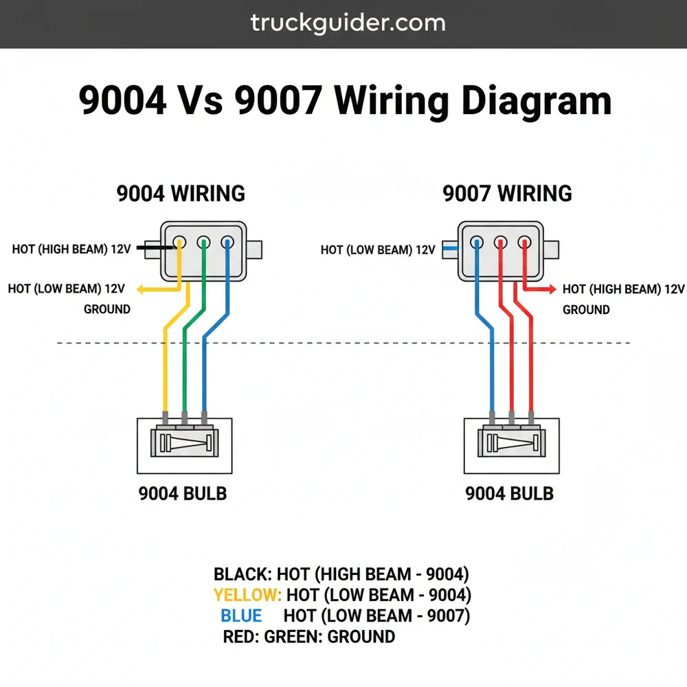
A 9004 vs 9007 wiring diagram illustrates that while both use a three-pin connector, the pinout differs significantly. In a 9004 bulb, the ground wire is the center pin, whereas 9007 bulbs use the center pin as the common terminal for high/low beams. Identifying the traveler wire and hot wire ensures correct function.
📌 Key Takeaways
- Explains the pinout differences between dual-filament bulbs
- Identifies the central ground vs. central common terminal orientation
- Prevents dim lights or circuit shorts caused by incorrect wiring
- Highlights the need for a multimeter to verify the hot wire
- Essential reference for HID or LED headlight conversions
Understanding the specific differences in a 9004 vs 9007 wiring diagram is essential for any automotive enthusiast or DIY mechanic looking to upgrade their lighting system or repair a faulty headlight harness. While these two bulb types look nearly identical to the naked eye, they are electrically incompatible due to different pin assignments and filament orientations. This comprehensive guide provides a deep dive into the wiring schematics, terminal identifications, and technical nuances that separate these two common halogen standards. By the end of this article, you will be able to identify each connection point, understand the role of the common terminal, and successfully execute a wiring conversion or repair with professional-grade accuracy.
The primary challenge when dealing with a 9004 vs 9007 wiring diagram is that the physical connector shell is the same, but the internal wiring logic is flipped. In a standard 9004 system, the ground wire is typically located at the center pin, whereas in a 9007 system, the ground is moved to one of the outer positions. Failing to recognize this shift can lead to dim lights, non-functional high beams, or even blown fuses within your vehicle’s electrical system. This guide will walk you through the color codes, wire gauges, and terminal sequences necessary to master this automotive wiring puzzle.
The 9004 bulb (HB1) and 9007 bulb (HB5) both feature a three-pin configuration, but their internal filament arrangement is different. The 9004 uses a transverse (horizontal) filament, while the 9007 uses an axial (vertical) filament. This makes the optics of the headlight housing specific to each bulb type.
Decoding the Main Wiring Diagram Components
When viewing a 9004 vs 9007 wiring diagram, you are looking at a three-terminal interface. Each terminal corresponds to a specific function: High Beam, Low Beam, and the Common Ground. To understand the visual breakdown, imagine the connector facing you with the locking tab at the top. This orientation is standard for identifying pin positions one, two, and three from left to right.
For a 9004 (HB1) connector, the pinout is generally structured as follows:
- ✓ Pin 1 (Left): High Beam (Hot Wire)
- ✓ Pin 2 (Center): Ground Wire (Common Terminal)
- ✓ Pin 3 (Right): Low Beam (Hot Wire)
Conversely, the 9007 (HB5) connector shifts these responsibilities significantly. In the 9007 configuration, the ground wire is no longer at the center. Instead, the diagram shows:
- ✓ Pin 1 (Left): High Beam (Hot Wire)
- ✓ Pin 2 (Center): Low Beam (Hot Wire)
- ✓ Pin 3 (Right): Ground Wire (Common Terminal)
– A visual representation showing the female harness connectors for both 9004 and 9007 side-by-side, highlighting the center pin as Ground for 9004 and the right-side pin as Ground for 9007.
The color-coding for these wires often varies by vehicle manufacturer, but the concept of the “hot wire” and “neutral wire” (or ground in DC systems) remains constant. Most aftermarket pigtails use black for the ground wire, red for the high beam, and white or blue for the low beam. However, you should always verify the voltage at each pin using a multimeter before making permanent connections. The gauge of the wire is also a critical element shown in the diagram; typically, 16-gauge or 14-gauge wire is used to handle the 12V to 14V current without excessive heat buildup.
Understanding the Common Terminal and Traveler Wire Concepts

In electrical engineering, specifically when discussing 3-way switching, terms like “traveler wire” and “brass screw” are common. In the context of an automotive headlight circuit, we can apply these concepts to describe how the signal moves from the headlight switch to the bulb. The headlight switch acts as the source, sending current through what functions as a traveler wire to either the high beam or low beam terminal. The “common terminal” in this scenario is the shared ground that completes the circuit for both filaments.
While you won’t find a brass screw on a plastic headlight connector, the metal pins inside serve the same
When performing a 9004 to 9007 swap, you don’t necessarily need to cut the wires. You can often “depin” the connector using a small flat-head tool, allowing you to move the terminals into the correct slots for the new bulb type without compromising the factory harness.
Step-by-Step Guide to Interpreting and Wiring the Diagram

Properly executing a 9004 vs 9007 wiring task requires a systematic approach. Follow these steps to ensure a safe and effective installation.
Step 1: Gather Necessary Tools and Materials
Before starting, ensure you have a digital multimeter, wire strippers, heat-shrink tubing, and a soldering iron (or high-quality crimp connectors). You will also need the correct gauge of wire—usually 16 AWG—to match the existing factory loom. If you are replacing a burnt connector, purchase a high-temperature ceramic pigtail rather than a standard plastic one.
Step 2: Identify Your Existing Harness Type
Consult your vehicle’s manual or check the markings on the existing bulb. A 9004 bulb will have the ground wire going to the middle slot of the female connector. A 9007 bulb will have the ground wire on the outer edge. Use your multimeter to confirm: set the meter to DC Voltage, turn on the low beams, and find which pin shows ~12V. Then turn on the high beams to find the other hot wire. The remaining pin that shows continuity to the chassis is your ground wire.
Step 3: Map the Connections
Draw a simple diagram of your current wires. Note which color corresponds to High, Low, and Ground. If you are converting from 9004 to 9007, your “map” will show that the wire currently in the center (9004 Ground) needs to move to the right-side position (9007 Ground), and the wire on the right (9004 Low Beam) needs to move to the center (9007 Low Beam).
Step 4: Prepare the Wires
If you are replacing the pigtail, cut the old connector off about 3 inches back from the plug. Strip approximately 1/4 inch of insulation from each wire. If you are depinning, carefully release the plastic tabs inside the connector and pull the terminals out from the back.
Step 5: Execute the Wiring Sequence
Following your map, connect the wires to the new terminals. If soldering, slide the heat-shrink tubing onto the wire first. Twist the strands together, apply heat and solder until the joint is fully wetted, and then slide the tubing over the joint and shrink it with a heat gun. This ensures the connection is weatherproof and vibration-resistant.
Step 6: Verify Terminal Security
Give each wire a gentle tug to ensure it is seated firmly in the connector. If you used crimp connectors, make sure the metal sleeve has bit into the copper wire and not just the insulation. A loose common terminal is the leading cause of intermittent headlight failure.
Step 7: Final Testing
Before reassembling the headlight housing, plug the bulb into the new harness. Turn on the vehicle’s accessory power and test the low beams, then the high beams. Check that the correct filament lights up for each setting. In a 9007 bulb, the low beam filament is usually the one with a small metal shield, while the high beam is unshielded.
Step 8: Secure and Protect
Once functionality is confirmed, wrap the harness in automotive-grade loom or electrical tape to protect it from heat and moisture. Ensure the wires are routed away from moving parts like fans or hot components like the radiator or exhaust manifold.
Never touch the glass of a halogen bulb with your bare fingers. The oils from your skin can create hot spots on the quartz glass, causing the bulb to shatter or burn out prematurely when it reaches operating temperature. If you touch the glass, clean it with rubbing alcohol before installation.
Common Issues & Troubleshooting
Even with a perfect 9004 vs 9007 wiring diagram, issues can arise during the installation or over time. One of the most frequent problems is “swapped polarity” logic. In some vehicles, the headlights are “ground-switched” rather than “power-switched.” This means the hot wire is always live, and the switch completes the ground path. If your diagram assumes a power-switched system but your car is ground-switched, the lights may stay on constantly or not work at all.
Another common issue is a melted connector. This usually happens when the common terminal (ground) becomes loose or corroded. Increased resistance at that point generates heat, which eventually liquefies the plastic. If you see signs of browning or melting on your 9004 or 9007 plug, the entire connector must be replaced.
If you experience “dimming” when switching to high beams, it often indicates that the ground wire and one of the hot wires have been swapped. In this scenario, the current is trying to find a path through both filaments in series, which significantly increases resistance and drops the voltage, leading to a faint orange glow rather than a bright white light.
- ! Flickering lights: Usually caused by a loose pin or a poor ground connection to the chassis.
- ! High beams won’t activate: Check the traveler wire signal from the column switch.
- ! Blown fuses: Indicates a short circuit where a hot wire is touching the ground wire or the vehicle frame.
Tips & Best Practices for Headlight Wiring
To achieve the best results with your 9004 vs 9007 wiring project, consider using a relay harness. A relay harness pulls power directly from the battery rather than through the thin factory wires and the headlight switch. This maximizes the voltage reaching the bulbs, often increasing brightness by 10-20%. When building a relay harness, use 14-gauge wire for the main power feed to minimize voltage drop over the length of the wire.
Maintenance is also key. Every few months, check the back of the headlight connectors for signs of moisture or corrosion. Applying a small amount of dielectric grease to the terminals can prevent oxidation and ensure a long-lasting connection. This is especially important for the common terminal, as it carries the combined current of whichever filament is active.
When choosing components, avoid cheap, unbranded pigtails found on discount sites. Look for connectors that specify “high-temp ceramic” or “OEM grade.” The heat generated by a 55W/65W halogen bulb is substantial, and low-quality plastics will fail prematurely. Furthermore, if you are upgrading to high-wattage bulbs (like 80W/100W variants), you must upgrade your wiring gauge and use relays, as the factory 9004 or 9007 wiring is not designed to handle the increased amperage.
Finally, always document your changes. If you have modified the pinout of a 9004 vs 9007 wiring diagram for a custom application, leave a small tag on the harness or a note in the owner’s manual. This will save significant time and frustration for you or the next owner when a bulb eventually needs replacement.
Technical Specifications and Comparison
To further clarify the 9004 vs 9007 distinction, let’s look at the electrical specifications. Both bulbs operate on a nominal 12.8V system. The 9004 bulb typically draws 45 Watts on low beam and 65 Watts on high beam. The 9007 bulb is slightly more powerful on the low side, typically drawing 55 Watts on low beam and 65 Watts on high beam.
The physical difference in the base is also a factor. Both bulbs use the same circular plastic base with three plastic “keyed” tabs. However, the positions of these tabs are slightly offset. While a 9007 bulb can sometimes be forced into a 9004 housing (or vice versa), the focal point of the filament will be incorrect. This results in a beam pattern that scatters light into the eyes of oncoming drivers rather than focusing it on the road. Therefore, even if you successfully navigate the 9004 vs 9007 wiring diagram, you must ensure you are using the bulb type that matches your headlight reflectors.
In summary, the transition between 9004 and 9007 systems is entirely manageable if you pay close attention to the common terminal location. By treating the wiring as a logical sequence of High, Low, and Ground, and using the right tools—like a multimeter and high-quality gauge wire—you can ensure your vehicle’s lighting system is safe, bright, and reliable. Whether you are performing a simple repair or a complex conversion, the 9004 vs 9007 wiring diagram remains your most important roadmap for success in automotive electrical work.
Frequently Asked Questions
Where is the bulb connector located?
The headlight connector is located behind the headlight assembly inside the engine bay. Access it by removing the protective dust cap or rotating the bulb lock ring. Once the assembly is accessible, you can trace the neutral wire and ground wire back to the vehicle’s main wiring harness plug.
What does the 9004 vs 9007 wiring diagram show?
The 9004 vs 9007 wiring diagram illustrates the specific pin assignments for ground, low beam, and high beam connections. It helps users distinguish between the 9004’s central ground configuration and the 9007’s central common terminal setup, preventing wiring errors during bulb swaps or harness upgrades.
How many wires does the bulb connector have?
Both 9004 and 9007 connectors utilize three wires. These typically include a shared ground wire or common terminal, plus two separate hot wire feeds for the high and low beam filaments. Despite having the same number of pins, the internal mapping of these wires is not interchangeable.
What are the symptoms of a bad headlight wiring connection?
Common symptoms include dim headlights, only one beam working, or flickering lights. If you miswire a traveler wire or neutral wire during a conversion, you might experience hyper-flashing or a complete failure to switch between high and low beams, potentially blowing a fuse or damaging the harness.
Can I convert 9004 to 9007 wiring myself?
Yes, you can perform this conversion by re-pinning the harness or using an adapter. You must carefully identify each traveler wire to ensure the high and low beam signals reach the correct pins. Always disconnect the battery before modifying any automotive electrical circuits to ensure safety.
What tools do I need for re-pinning a 9004/9007 connector?
You will need a small flat-head screwdriver or a dedicated terminal release tool to de-pin the connector. A multimeter is essential to identify the hot wire and ground wire. Additionally, wire strippers and electrical tape or heat shrink tubing are helpful for securing any new connections.

![2nd Gen Dodge Ram Sport Bumper: Buying & Fitment Guide [2026]](https://truckguider.com/wp-content/uploads/2026/03/2nd-gen-dodge-ram-sport-bumper-featured.webp)
![How To Program A Dodge Key Fob [2026]](https://truckguider.com/wp-content/uploads/2026/03/featured-45ae9f7f-768x403.webp)
![Ram Trx Top Speed Without Limiter [2026]](https://truckguider.com/wp-content/uploads/2026/03/featured-cb0fbb5b-768x432.webp)
![P0740 Dodge Caravan: Complete Repair Guide [2026]](https://truckguider.com/wp-content/uploads/2026/03/featured-8988a183-768x768.webp)