Crankcase Pressure Sensor: Specs, Symptoms & Testing

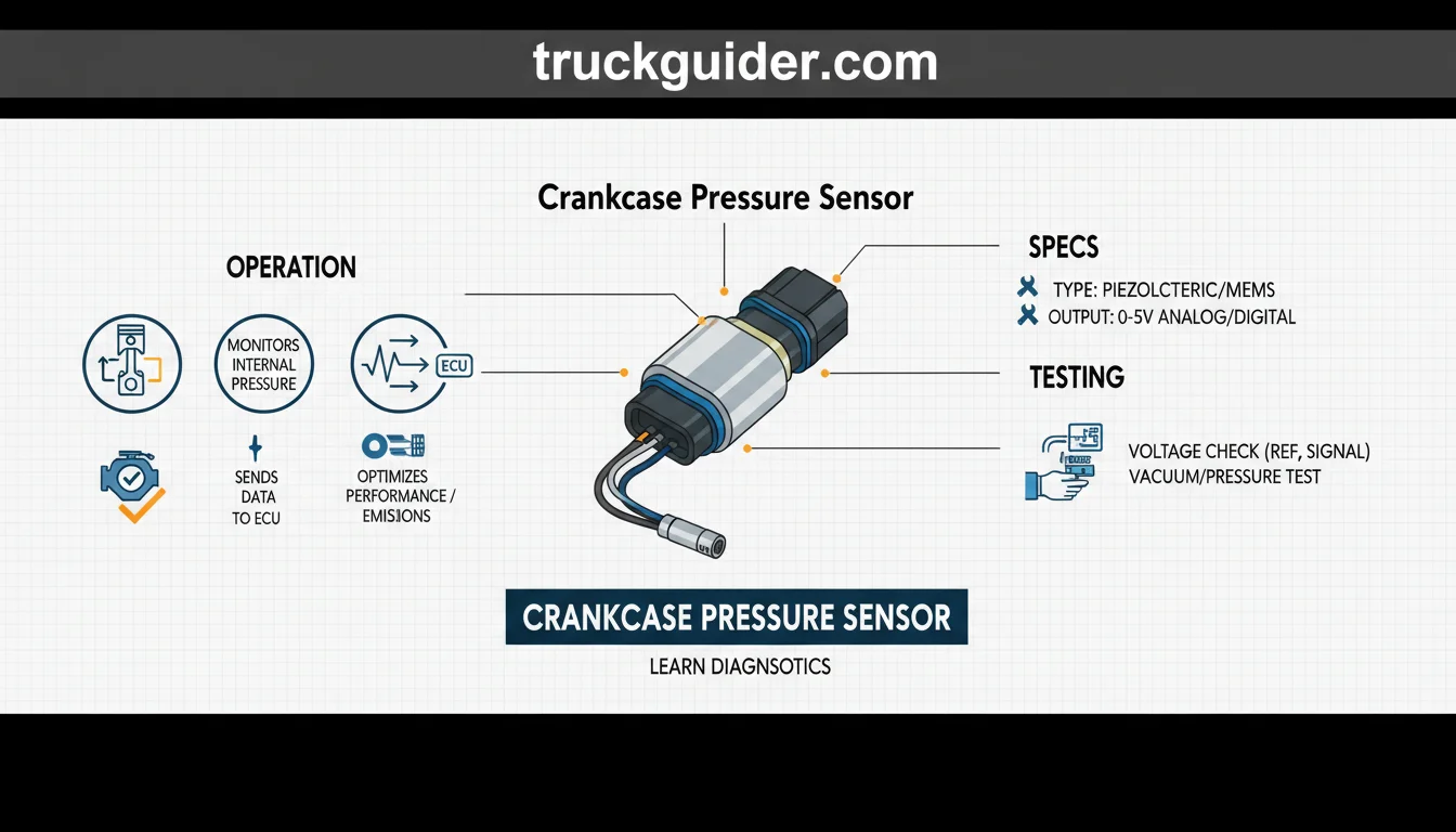
A sudden oil leak or check engine light often traces back to an overlooked culprit inside the engine block. A crankcase pressure sensor monitors the internal air and gas pressure within the crankcase, transmitting real-time voltage data to the engine control module (ECM) to keep internal forces balanced.
Excess positive pressure from blow-by gases can blow out main seals and damage internal parts. This dedicated sensor acts as an early warning safeguard, helping the ECM manage crankcase ventilation systems and protect engine health.

Prime for Young Adults — 6 Months Free
Students and 18–24s get six months of Prime free, then half price.
Start 6 Months FreeBelow, we examine the sensor’s internal design, core electrical specifications, diagnostic trouble symptoms, and step-by-step testing methods to help you isolate faults quickly.
What Is a Crankcase Pressure Sensor and Why Does It Matter?
Recommended Best Deal Products


A crankcase pressure sensor—frequently called a crankcase depression sensor or closed crankcase ventilation (CCV) pressure sensor—measures gas accumulation within the engine block. Its primary task is continuously monitoring internal positive pressure and vacuum relative to ambient conditions, providing critical operational data to the powertrain management system.

By transmitting real-time telemetry to the engine control module (ECM), the sensor acts as a frontline defense against catastrophic seal failure. Early diagnostic warnings alert operators to pressure spikes before they blow out valve cover gaskets, dislodge dipstick tubes, or force oil past front and rear main crankshaft seals.
Normal Crankcase Pressure vs. Abnormal Pressure Spikes
During normal operation, an internal combustion engine maintains crankcase pressure near atmospheric baseline. A properly functioning ventilation system typically pulls a slight vacuum (depression) or holds near-zero relative pressure. Continuous, unmitigated positive pressure signifies a mechanical issue, such as excessive piston ring blowby or line restrictions.

Dynamic variations naturally occur across varying engine loads. For example, a heavy-duty diesel engine might pull a mild 0.5 kPa vacuum during highway cruise, while transitioning to 1.5 kPa of positive pressure under full load conditions before the ventilation circuit re-establishes balance.
Emissions Mandates and Closed Crankcase Ventilation (CCV)
Stringent commercial vehicle emissions regulations mandate crankcase pressure monitoring to ensure environmental compliance. Historically, crankcase vapors vented directly into the environment through open road draft tubes, releasing raw blowby and oil particulates. Modern standards strictly prohibit this practice.
Today’s closed crankcase ventilation (CCV) systems route blowby gases back through the intake to be burned in the combustion chamber. The sensor actively detects CCV bypasses, missing filters, or system ruptures that discharge unburned hydrocarbons and volatile organic compounds straight into the atmosphere.
Inside the Sensor: Anatomy, Components, and Operation Details
Piezoresistive Sensing Element and Diaphragm Deflection
Operation begins at the sensor probe nipple, which interfaces directly with the engine block or valve cover. Crankcase vapors enter this port to exert pressure directly against a micromachined, flexible silicon or ceramic diaphragm.

Audible — Listen Free for 30 Days
One free credit a month and thousands of titles included.
Listen Free for 30 DaysIntegrated across this diaphragm is a piezoresistive Wheatstone bridge circuit. As positive or negative pressure flexes the membrane, mechanical strain alters the electrical resistance of the conductive traces, shifting the raw millivolt output proportional to diaphragm deflection.
A deflection of mere micrometers on the internal silicon membrane is enough to shift the ASIC processed output from a 2.5V baseline ambient state up to 4.2V during high-pressure events.
ASIC Signal Conditioning and Circuitry
The sensor relies on an onboard Application-Specific Integrated Circuit (ASIC) positioned adjacent to the sensing cell. The engine control module provides a stable supply voltage: 5 (regulated reference) V DC (varies by ECM architecture) to power these internal microelectronics.
Because raw bridge outputs fluctuate with engine heat, the ASIC applies real-time thermal compensation and linear scaling. It processes this data into a standardized signal output range: 0.5 to 4.5 V DC (varies by sensor manufacturer calibration curve or analog vs. SENT digital protocol).
Probe Port Design and Environmental Sealing
Engine blowby contains an aggressive mix of soot, atomized engine oil, moisture, and combustion gases. To prevent operational degradation, the internal circuitry is hermetically isolated from the gas measurement chamber via passivated gel barriers.
External protection is maintained through dedicated hardware boundaries. A high-temperature fluoropolymer mounting O-ring seals the sensor body to the engine port, while a sealed multi-pin automotive harness connector locks out ambient moisture, dirt, and external engine-bay degreasers.
Key Technical Specifications and Operating Range Overview
Recommended Best Deal Products


Crankcase pressure sensors operate within narrow electrical and mechanical boundaries to detect subtle internal engine pressure shifts. Standard units rely on a 5 (regulated reference) V DC supply voltage (varies by ECM architecture) to drive internal piezoresistive sensing elements.
The standard analog signal output range runs from 0.5 to 4.5 V DC (varies by sensor manufacturer calibration curve or analog vs. SENT digital protocol). This spans low-vacuum states up to critical overpressure limits before triggering diagnostic trouble codes.
Audible Premium Plus — Annual Membership
12 audiobook credits up front, plus the full Audible catalogue.
See Annual PlansSensor pressure measurement ranges scale depending on engine platform demands. Heavy-duty commercial platforms require ultra-sensitive spans, whereas light-duty passenger vehicles often encounter wider crankcase sweeps. Thermal resilience is equally vital, as sensors endure continuous heat soak from cylinder blocks, valve covers, and nearby turbocharger oil drain lines.
How to Read This Chart
This table compares baseline engineering parameters across distinct vehicle segments. The “Application Class” column categorizes the engine platform, separating heavy-duty commercial truck setups from standard automotive configurations. Pressure units vary between rows: heavy-duty highway diesels (such as Cummins ISX or Detroit DD15) use millibar (mbar) calibrations to detect minuscule fractional changes, while automotive engines track wider spans measured in kilopascals (kPa).
The “Supply Voltage” and “Signal Output” columns denote operating electrical thresholds provided by and returned to the ECM. Signal returns reflect either standard analog voltage curves or digital Single Edge Nibble Transmission (SENT) protocols. Temperature ranges display continuous ambient tolerances required to survive surrounding engine bay heat.
Crankcase Pressure Sensor vs. MAP, BARO, and Oil Pressure Sensors
Modern engine control modules (ECMs) monitor multiple pressure parameters across intake, lubrication, and ventilation systems. Because these sensors share similar naming conventions on diagnostic interfaces, technicians frequently confuse their operational roles, operating media, and baseline reference scales.
Crankcase Pressure vs. Manifold Absolute Pressure (MAP)
A Manifold Absolute Pressure (MAP) sensor measures air charge density within the intake manifold runners. It operates across a wide pressure spectrum, tracking deep vacuum during engine overrun (roughly 20 to 30 kPa absolute) up to high positive boost levels (200 to 400+ kPa absolute) on turbocharged configurations.
By contrast, a crankcase pressure sensor monitors low-pressure gaseous vapor accumulation inside the engine block airspace. Its operational range is extremely narrow, tracking slight positive or negative deviations around atmospheric pressure rather than dynamic airflow delivery.
Diagnostic confusion frequently occurs when interpreting scan tool live data. A technician may read a 101 kPa absolute reading on a scan tool and assume massive crankcase overpressurization, unaware that 101 kPa absolute simply reflects standard 0 kPa atmospheric gauge pressure.
The Role of the Barometric Pressure (BARO) Sensor
The Barometric Pressure (BARO) sensor monitors ambient atmospheric pressure surrounding the vehicle. Because local atmospheric pressure fluctuates based on weather and altitude—ranging from roughly 70 kPa in high-elevation regions to 101.3 kPa at sea level—it provides an indispensable baseline reference.
The ECM continuously correlates the crankcase pressure sensor reading against the BARO sensor signal. By subtracting ambient barometric pressure from raw absolute crankcase values, the controller calculates true gauge differential, allowing it to verify whether the crankcase maintains appropriate negative depression or dangerous positive vapor accumulation.
Crankcase Pressure vs. Engine Oil Pressure
The most critical distinction lies between crankcase vapor sensors and engine oil pressure sensors. An engine oil pressure sensor measures liquid hydraulic oil pressure generated by the mechanical oil pump (typically 1.5 to 6 bar under normal operating conditions) to verify bearing lubrication.
In contrast, the crankcase sensor never interacts with pressurized fluid galleries. It measures only the dry airspace vapors—consisting of blow-by gases and suspended oil aerosol—vented through the block, making its operating pressure hundreds of times lower than liquid lubrication pressure.
How to Read Pressure Sensor Diagnostic Specifications
When reviewing live sensor parameters, verify the reporting unit and datum reference configured in your diagnostic software. Values labeled absolute (psia or kPaa) measure pressure against a complete vacuum, meaning standard sea-level atmosphere displays as approximately 101.3 kPa (14.7 psi).
Conversely, gauge measurements (psig or kPag) calibrate zero against prevailing atmospheric pressure. Because crankcase pressure sensors operate within fractions of a bar, some scan tools report absolute values while others calculate differential gauge pressure automatically via BARO offsets.
Always verify whether your diagnostic interface reports engine oil pressure in bar, psi, or kPa. Confusing liquid oil pressure channels with crankcase vapor channels will lead to misdiagnosed mechanical faults and unnecessary component replacements.
Common Symptoms of a Failing Crankcase Pressure Sensor or System
Oil Leaks, Seal Weeping, and Dipstick Tube Ejection
Excess internal crankcase pressure actively seeks the path of least resistance. When venting pathways fail, expanding blow-by gases force motor oil past valve cover gaskets, oil pan mating surfaces, and up through the dipstick tube, occasionally unseating the dipstick entirely.
Ignoring oil leaks around the crankshaft front/rear main seals after seeing a crankcase pressure fault code risks catastrophic seal blowout and rapid oil loss. While an electronic sensor failure cannot mechanically force an oil leak, it blinds operators to severe over-pressurization before rotational barriers breach.
Engine Control Module (ECM) Derate and Warning Lamps
Modern engine controllers continuously monitor crankcase feedback to protect internal hardware. Drivability suffers when out-of-range signals register, such as an ECM initiating a 25% torque derate on a freight truck after recording crankcase pressure exceeding 5 kPa for more than 10 continuous seconds.
Technicians must distinguish between actual mechanical pressure events and erroneous sensor data. The sensor port is prone to oil sludge, carbon buildup, and soot accumulation, which can cause erratic readings or false fault codes. Clogged sensor ports trick the ECM into defensive derates despite normal crankcase conditions.
Turbocharger Drain Backup and Intake Oil Mist
Turbochargers rely on uninterrupted gravity drainage to return cooling oil directly into the oil pan. Elevated crankcase pressure generates pneumatic resistance inside the drain pipe, preventing oil from exiting the center rotating housing assembly effectively.
This oil backup overwhelms internal dynamic piston seals, migrating directly into the compressor and turbine housings. Observable symptoms include persistent blue-gray exhaust smoke, oil pooling inside the charge air cooler pipes, and heavy oil mist entering the combustion chambers.
Sensor Failure vs. Plugged CCV Filter: Diagnostic Insights
High crankcase pressure alerts are more commonly caused by clogged CCV coalescer filters or excessive ring blowby than by an actual sensor circuit failure. Misinterpreting the diagnostic trouble code often leads technicians to swap parts unnecessarily.
Inspecting the Crankcase Breather Filter and Coalescer Element
Replacing the sensor immediately without checking for a saturated CCV filter element or collapsed breather hose leads to repeat trouble codes. Over time, the internal coalescing media traps oil aerosols until crankcase gases can no longer vent freely.
For example, a Cummins X15 displaying SPN 101 FMI 0 is often caused strictly by an oil-saturated coalescer filter past its 100,000-mile service interval. The sensor is reading accurately; the crankcase is simply over-pressurized.
Before condemning the sensor, also inspect the sensor fitting and passage. Physical port blockages caused by baked soot and emulsified oil sludge will trap pressure against the sensing diaphragm, generating false high-pressure readings even after the engine stops.
Evaluating Piston Ring Blowby and Liner Wear
If the crankcase ventilation filter is clean, investigate upstream mechanical root causes. Combustion blowby occurs when hot gases bypass worn piston rings, damaged ring lands, or scored cylinder liners.
This bypass volume can overwhelm an entirely functional ventilation system. A fresh filter cannot mitigate mechanical gas leakage, causing the crankcase pressure sensor to continuously trip high-limit faults under heavy engine loads.
Physical Pressure Verification with a Water Manometer
Never rely solely on scanner data to diagnose an over-pressure condition. Perform a mechanical manometer or water-column test to verify physical crankcase pressure against live sensor telemetry.
Connect a slack-tube water manometer or digital differential pressure gauge to the dipstick tube or crankcase inspection port. Run the engine under load and measure the displacement in inches of water (in-H2O).
If the physical gauge reads within normal factory limits while the ECM reports elevated values, suspect a skewed sensor, port debris, or circuit resistance issues.
📋
Step-by-Step Guide to Testing and Inspecting the Sensor
Bench Testing Sensor Reference and Signal Voltages
Disconnect the 3-wire harness with the key-on engine-off (KOEO). Set your digital multimeter to DC volts to verify a regulated 5.0V reference feed from the engine controller. Switch to resistance mode to verify the ground return circuit measures below 0.5 ohms.
Reconnect the harness and backprobe the signal wire. Standard analog units operate within a signal output range of 0.5 to 4.5 V DC, governed by the sensor manufacturer calibration curve (digital SENT protocols require an oscilloscope). Check KOEO base voltage, then monitor for smooth transitions during engine RPM sweeps.
Visual Inspection and Safe Port Cleaning Protocol
Remove the sensor mounting bolt and extract the unit. Check the probe orifice for carbon sludge, emulsified oil gumming, and soot blockages. Inspect the elastomer O-ring for hardening, flat-spotting, or tears that permit unmetered air leakage.
Never clean the port with aggressive brake cleaners or high-pressure shop air, which can rupture the internal silicon diaphragm. Instead, apply low-pressure contact cleaner and a lint-free swab to clean the port rather than using a 120 PSI shop air nozzle.
Confirming Live Scan Tool Telemetry
Reinstall the sensor and connect a diagnostic scan tool to view live data. Compare the reported live sensor voltage and calculated crankcase pressure against an independent, calibrated external gauge plumbed into the dipstick tube or crankcase inspection port.
Typical Mounting Locations and Maintenance Facts Across Engine
Valve Cover vs. Filter Housing Sensor Locations
Crankcase pressure sensors reside in distinct environments depending on the engine architecture. Common mounting spots include the upper valve cover, the engine block skirt above the oil pan rail, or directly on the crankcase ventilation (CCV) filter module housing.
For example, Detroit DD13 and DD15 platforms locate the sensor on the flywheel-end CCV module housing. Conversely, a Cummins ISX15 or X15 typically threads the sensor into a driver-side valve cover port. Light- and medium-duty platforms, including Ford Power Stroke and GM Duramax engines, often position crankcase depression sensors near the valve cover or CCV separator lines.
Regardless of placement, the sensor port is prone to oil sludge, carbon buildup, and soot accumulation, which can cause erratic readings or false fault codes if particulate obstructs the internal diaphragm aperture.
Wiring Harness Stress and Thermal Protection
Mounting near cylinder heads exposes sensor pigtails to high radiant heat and heavy mechanical vibration. Inspect the wiring conduit regularly for chafing against metal brackets and oil-soaking from adjacent seals.
Ensure wire leads maintain adequate slack to absorb engine movement. Brittle insulation or micro-fretting inside the three-pin connector shell frequently introduces intermittent voltage drops that mimic sensor failure.
Preventative Inspection Schedule and Reassembly
Align sensor inspections with scheduled coalescer filter changes, typically every 50,000 to 75,000 miles in commercial applications. Inspect the elastomeric seal for swelling, hardening, or flattening at every routine oil maintenance interval.
During reinstallation, coat new fluorocarbon O-rings with clean engine oil to avoid pinching or tearing during insertion. Always secure mounting fasteners to factory torque specifications—typically 8 to 12 Nm—to prevent cracking the composite sensor body while maintaining a hermetic seal against crankcase gases.
Key Takeaways
-
✓
Monitors critical crankcase atmospheric deviations, typically measuring narrow ranges between -5 kPa and +15 kPa (-0.7 to +2.2 psi). -
✓
Differentiates crankcase issues from oil pressure faults by tracking gas accumulation rather than liquid lubrication delivery. -
✓
A flashing check engine light accompanied by DTCs P051B through P051E signals electrical circuit faults or out-of-range sensor info. -
✓
Physical inspection requires checking the sensor sensing port for oil sludging and carbon fouling that causes sluggish voltage output. -
✓
Diagnostic insights highlight that high crankcase pressure frequently stems from a plugged coalescing filter rather than an electrically dead sensor.
❓ Frequently Asked Questions
1
What is a crankcase pressure sensor?
A crankcase pressure sensor is a specialized piezoresistive transducer that measures internal vapor pressure inside the engine block. It provides essential info to the engine control module, alerting the system when blow-by gases exceed safe thresholds or when crankcase depression drops low enough to pull dirt past main oil seals.
2
How does a crankcase pressure sensor work?
The sensor contains a flexible piezoresistive diaphragm exposed to crankcase vapors on one side and a reference vacuum or atmospheric chamber on the other. Pressure changes deflect this membrane, altering electrical resistance and producing a linear 0.5-volt to 4.5-volt signal that communicates exact pressure details to the vehicle controller.
3
Why is crankcase pressure monitoring important?
Monitoring crankcase pressure prevents catastrophic engine failures by catching piston ring blow-by, turbocharger seal leaks, and PCV restrictions early. Accurate sensor information prevents positive pressure from blowing out front and rear crankshaft seals, which causes rapid engine oil starvation, environmental contamination, and costly roadside breakdowns.
4
How do you differentiate sensor failure from a plugged CCV filter?
Diagnostic insights require measuring mechanical pressure with an external water manometer. If crankcase pressure reads high on both your manual gauge and scan tool, the CCV filter is clogged. If the manual gauge shows normal atmospheric conditions while the scanner reads extreme positive pressure, the sensor is defective.
5
How do you test a crankcase pressure sensor?
Begin by checking for a 5-volt reference and solid chassis ground at the wiring harness connector. Next, monitor live signal wire voltage using a digital multimeter while applying gentle pressure with a handheld mityvac pump. Crucial facts confirm healthy sensors sweep smoothly without signal dropouts or dead zones.
6
What are the most common symptoms of a bad crankcase pressure sensor?
Highlight diagnostic trouble codes (e.g., SPN 101 / FMI codes), yellow or red stop-engine warning lamps, unprompted engine derates, and erratic pressure fluctuations on live scan tool streams that do not match engine RPM.