Ford F150 Engine Swap Chart: 2026 Component Breakdown

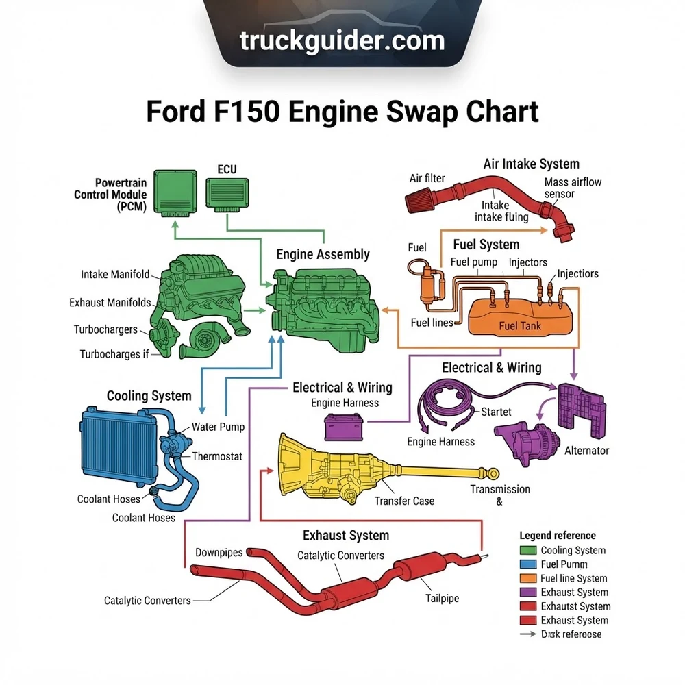
The engine swap chart outlines the structural integration between the PCM, engine harness, and chassis configuration. Key identification includes pin-out compatibility for modular engine blocks (5.0L Coyote vs 3.5L EcoBoost), coolant hose routing, and transmission interface protocols. Refer to the specific wire color-code grid for ECU connector mapping and sensor synchronization.
📌 Key Takeaways
- Compatibility requires matching PCM hardware versions to the specific engine block casting (2015-2026 models).
- Ensure the CAN-bus communication structure remains intact during harness modification to prevent limp-mode activation.
- Always torque bell housing bolts to 55 ft-lbs and verify grounds at the engine block to chassis contact points.
- The most common failure point is the mismatch of fuel pressure regulator settings between generation-specific fuel systems.
- Seek professional diagnostic assistance if PCM re-flashing is required for immobilizer (PATS) security clearance.
Executing a successful engine transplant in a Ford F-150 requires more than mechanical aptitude; it demands a deep understanding of the vehicle’s complex electrical architecture and drivetrain integration. Whether you are upgrading to a high-output Coyote V8 or performing a modular engine swap, the complexity of modern chassis integration necessitates a standardized approach. Utilizing a reliable Ford F150 engine swap chart allows builders to navigate the nuances of the Ford modular engine family, ensuring that the engine control module (ECM), transmission, and peripheral systems communicate effectively. This article provides the technical blueprint required to transition from a factory configuration to a customized performance powertrain, focusing on data-driven compatibility and system-wide reliability.


Ford F150 Engine Swap Chart: Essential Component Breakdown

Successful engine integration relies on identifying the compatibility between the donor engine and the host chassis. The Ford modular engine family (4.6L, 5.4L, 5.0L Coyote) presents unique mounting and communication challenges. When referencing the Ford F150 engine swap chart, the primary objective is to verify that the physical structure of the engine block mounts aligns with the chassis perches or adapters.
The engine control module (ECM/ECU) serves as the brain of the operation. In later model F-150s, the ECU is deeply integrated with the body control module (BCM) and the instrument cluster via a high-speed CAN-bus network. If you are swapping an engine that utilizes a different generation of control logic, you must account for signal translation. The following table provides a quick-reference guide for identifying compatibility between common engine systems and their necessary support components.
| Engine Type | ECU Compatibility | Transmission Interface |
|---|---|---|
| 2V Modular (4.6/5.4) | Factory PCM (97-03) | 4R70W/4R75E |
| 3V Modular (5.4) | Factory PCM (04-08) | 4R75E/6R80 (requires adapter) |
| 5.0L Coyote (Gen 1-3) | Standalone Control Pack | 6R80 / 10R80 |
| EcoBoost (3.5L) | Chassis-specific Harness | Direct bolt-in (specific bellhousing) |
The transmission adapter plate is often the most overlooked component in the configuration. When swapping an engine into a chassis originally equipped with a different transmission bolt pattern, the adapter plate must account for the starter location and torque converter offset. Failure to align these components precisely results in premature bearing failure and potential flywheel damage.
Always verify the crank position sensor (CKP) signal pattern before finalizing your wiring harness. Different modular engine generations utilize varying reluctor wheel tooth counts, which can lead to no-start conditions even if the engine turns over normally.
Planning Your Ford F150 Engine Swap: A Step-by-Step Guide
Strategic planning is the foundation of a reliable conversion. The process must follow a logical progression to ensure that mechanical, electrical, and data systems integrate without conflict.


1. Chassis and Engine Assessment: Begin by evaluating the physical envelope of your engine bay. Compare the dimensions of the donor engine with the original configuration. Note the location of the power steering pump, alternator, and A/C compressor.
2. Electrical Harness Mapping: Map your wiring harness against the chassis blueprint. If you are integrating a modern Coyote engine into an older chassis, you will likely need a standalone engine management system (EMS) to bypass the complex factory anti-theft and communication modules.
3. CAN-bus Integration: Modern F-150s require constant communication between the engine, transmission, and ABS modules. If your swap disrupts this path, you must install a CAN-bus bridge or utilize an aftermarket harness designed to provide “clean” signals to the body controller, preventing limp-mode activation.
4. Fuel Delivery System: Ensure the fuel pump and regulator can support the pressure requirements of your new powerplant. The fuel rail pressure sensor on a 5.0L Coyote, for instance, requires a specific feed that differs from the return-style systems of older 4.6L modular motors.
5. Cooling and Induction: Match the radiator core capacity to the new engine’s heat rejection requirements. Ensure the intake ducting aligns with the factory air-box mounting points if possible to maintain a clean aesthetic and functional airflow.
6. Initial System Test: Before cranking the engine, use an OBD-II scanner to monitor live data. Verify that the coolant temperature sensor, intake air temperature sensor, and MAP sensor are reporting plausible values.
For Gen 2 Coyote swaps, target a base ECU calibration that accounts for the composite intake manifold resonance. Use a 100-micron fuel filter to protect the high-pressure fuel injectors from debris during the initial break-in period.
Ford F150 Engine Swap Chart: Common Pitfalls and Troubleshooting
Even with a detailed Ford F150 engine swap chart, technical challenges often arise. Identifying these failure points early saves significant diagnostic time.
Incorrect Accessory Drive Alignment: Mismatched pulley offsets are a common cause of belt shredding. Verify the alignment of the water pump, alternator, and A/C compressor using a straight-edge tool. Ensure your F-150 configuration accounts for the specific depth of the timing cover.
Pinout Compatibility Errors: Wiring harness conflicts are the most frequent cause of engine swap stalls. A single mispinned ground can lead to sensor noise, causing erratic engine behavior or phantom diagnostic trouble codes (DTCs). Always cross-reference the factory schematic with your custom harness diagram.
Improper Grounding Strategy: High-performance engines require robust grounding. Ensure the block-to-chassis and engine-to-battery grounds are sized correctly (minimum 2-gauge cable). Insufficient grounding leads to voltage drops that interfere with sensitive ECU signals.
Exhaust Manifold Interference: In many swaps, the stock exhaust manifolds interfere with the frame rails. You may need to transition to mid-length or long-tube headers. Verify the position of the O2 sensor bungs; they must be positioned to avoid turbulence while remaining within the ECU’s switching parameters.
* Immobilizer Conflicts: In vehicles produced after 2005, the Passive Anti-Theft System (PATS) is tied to the ECU and the cluster. If the key chip does not match the ECU, the engine will crank but fail to fire. Using a standalone control pack is the industry-standard workaround for this limitation.
Never attempt to bypass the factory immobilizer by “hard-wiring” the fuel pump relay. This creates a severe fire risk and prevents the ECU from managing fuel pressure correctly during high-load conditions.

Legal Requirements and Compliance for F150 Drivetrain Upgrades
Regulatory compliance is a critical aspect of any engine swap. In many jurisdictions, installing an engine from a vehicle that is older than the host chassis is prohibited. Furthermore, the engine must be equipped with the complete emissions control system mandated for its model year.
When performing a swap, prioritize the use of Ford Performance control packs. These kits include a pre-calibrated ECU and a simplified, standalone harness designed to meet emissions and performance standards in a variety of non-stock configurations. Because these packs are designed by Ford engineers, they ensure that the engine management system operates within the OEM specifications for air-fuel ratios and timing, which is vital for passing tailpipe emissions tests.
Documenting the donor vehicle’s VIN and obtaining a formal bill of sale for the engine is essential. Many states require this documentation to certify the vehicle for street use after a major drivetrain modification. Always check with your local Department of Motor Vehicles or environmental protection agency regarding specific testing procedures for modified light trucks. Failure to meet these requirements can lead to registration denial or the inability to obtain insurance for the modified vehicle.
Frequently Asked Questions About Engine Swaps
Can I use my factory transmission with a newer Coyote engine?
Yes, but you will likely need a transmission adapter plate and a modified flexplate to match the crankshaft bolt pattern. Additionally, the transmission controller (TCM) must be able to communicate with the engine’s new ECU, which often requires a standalone controller if you are using a non-matching transmission.
How do I handle the BCM and instrument cluster after a swap?
If you are moving away from the factory PCM, the original instrument cluster may stop displaying engine data like RPM or oil pressure. You will need to install aftermarket gauges or a CAN-bus bridge module that interprets the digital signals from the new ECU and converts them into an analog format that the cluster can read.
What is the most reliable way to handle the wiring harness?
The most reliable method is to purchase a purpose-built, plug-and-play wiring harness. Building a harness from scratch requires thousands of pin-to-pin verifications and exposes the system to potential failure points. Modern aftermarket harnesses come labeled and are designed to interface directly with the factory chassis plugs.
Do I need to upgrade my cooling system when doing an engine swap?
Absolutely. Newer engines, such as the 5.0L Coyote, operate at higher thermal loads than the older 4.6L and 5.4L Triton motors. A custom radiator with increased core surface area, combined with high-flow electric fans triggered by the ECU, is necessary to maintain safe operating temperatures.
How do I troubleshoot a no-start condition after the swap?
First, check for a “crank but no start” scenario. Verify your fuel pressure at the rail and confirm that your injectors are receiving a pulse signal from the ECU. Use a scan tool to check for a “RPM signal” while cranking; if the ECU does not see a signal from the crankshaft position sensor, it will not trigger the spark or fuel pulse, preventing the engine from running.