Outside Air Temperature Sensor Location Expert 2026 Guide

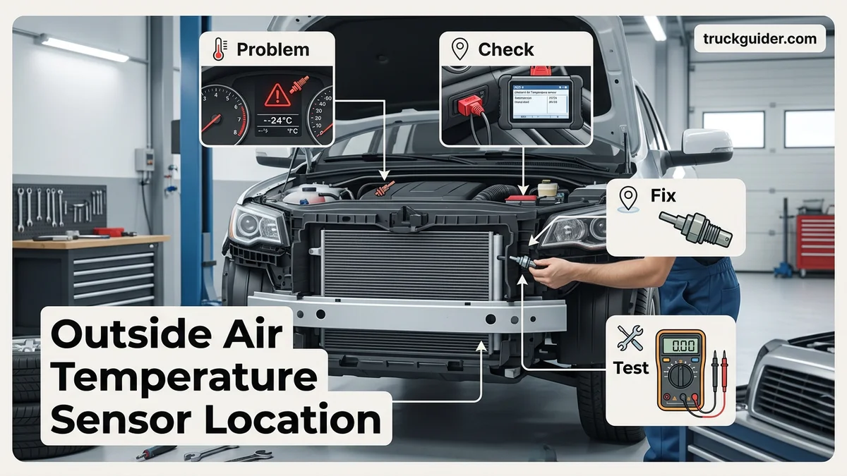
The outside air temperature sensor location is most commonly behind the front lower bumper grille or mounted on the radiator core support, though select vehicles house it beneath the passenger side mirror. This small, two-wire plastic probe monitors ambient air while isolated from engine heat to regulate your dashboard readout and automatic climate control. A dislodged or defective sensor leads directly to faulty dashboard gauge readings and erratic AC cooling performance.
On roughly 85 percent of modern vehicles, the outside air temperature (ambient) sensor sits directly behind the lower front bumper grille, snapped onto the radiator support or a center vertical brace. A smaller selection of vehicles—notably modern European models and several light trucks—places the sensor underneath the driver- or passenger-side exterior mirror housing.
Tracking down this physical component is essential when troubleshooting climate control failures. Your vehicle’s climate computer and engine management rely directly on this sensor. If it breaks or comes loose, your automatic air conditioning can shut down, your defrosters may malfunction, and 2026 hybrid or EV thermal management systems can miscalculate battery conditioning cycles.
Key Takeaways
- Most vehicles mount the sensor behind the front lower bumper grille on a radiator support bracket.
- European and select modern models frequently place the ambient sensor underneath the passenger side-view mirror housing.
- Look for a small black plastic probe secured with a push-pin clip and a two-wire harness.
- Faulty readings directly disrupt automated climate control systems, causing improper cabin heating and cooling cycles.
- Access typically requires reaching behind the lower grille or dropping the plastic front engine splash shield.
What Causes Outside Air Temperature Sensor Reading Errors and Failures
Recommended Best Deal Products

Physical Impact and Road Debris
Because most manufacturers mount the sensor in the lower front fascia, it sits directly in the path of road hazards. Rocks, winter road salt, road kill, and high-pressure car wash sprays frequently strike the housing. Common physical failures include:
- Shattered probe bodies: Flying gravel punches through plastic grille slats, cracking the sensor casing and exposing the thermistor element inside.
- Harness corrosion: Water and de-icing chemicals seep past weathered rubber weather-pack seals, greening the copper terminals and raising electrical resistance.
- Broken mounting tabs: Striking parking curbs or snowbanks snaps the brittle plastic push-pin clip, leaving the sensor dangling by its wires.
Thermal Interference and Circuit Faults
A sensor that reads incorrectly often suffers from heat soak rather than an internal electrical failure. If the probe slips out of its bracket and rests against the hot air conditioning condenser or radiator, your dashboard display will spike to 120°F or higher on a mild day. Conversely, a completely severed wire or unplugged connector defaults the circuit to maximum electrical resistance, causing the gauge cluster to display an impossible reading like -40°F or blank dashes. When this happens, your climate control module assumes freezing ambient conditions and refuses to cycle the A/C compressor clutch.
Master Ambient Air Temperature Sensor Location in 7 Simple Steps
Your vehicle’s ambient or outside air temperature (OAT) sensor feeds critical environmental data to your dashboard display, automatic climate control system, and engine control unit. When this sensor fails or misreads, you might notice your air conditioning blowing warm air or your instrument cluster displaying nonsensical values like -40°F (-40°C) or 122°F (50°C). Locating this sensor is the first and often most challenging step in troubleshooting, as manufacturers conceal it behind body panels to protect it from direct engine heat and road debris. Following this walkthrough will help you quickly pinpoint, access, and verify the outside air temperature sensor on virtually any modern car, truck, or SUV.
Step 1: Research Vehicle-Specific Placement and Schematics
What you need: Owner’s manual, vehicle repair guide (such as Haynes, Chilton, or an OEM digital service portal), and your vehicle’s VIN.
Instructions: Start by consulting your factory service literature or an online OEM parts diagram using your specific Vehicle Identification Number (VIN). Automobile manufacturers position ambient sensors in locations that receive continuous, clean airflow while remaining shielded from radiant engine heat. Approximately 85% of modern consumer vehicles mount this sensor directly behind the front bumper fascia or lower grille. However, notable exceptions exist: several European and Chrysler/Fiat models integrate the sensor into the underside of the driver or passenger side-view mirror housing. Knowing your vehicle’s general blueprint beforehand prevents unnecessary disassembly of front-end components.
Pro Tip: Look closely at parts diagrams for the “Ambient Temperature Sensor” bracket; the shape of the bracket usually indicates whether it clips onto a vertical radiator support strut, a horizontal crash bar, or a mirror shell.
Step 2: Prepare a Safe, Illuminated Workspace
What you need: Safety glasses, mechanic’s gloves, wheel chocks, a high-lumen LED work light or headlamp, and a 10mm wrench.
Instructions: Park the vehicle on a level concrete surface, engage the emergency parking brake firmly, and chock the rear wheels. Allow the engine to cool for at least 30 to 45 minutes; you will be working near the radiator and condenser, which retain intense heat that can cause severe contact burns. Pop the hood to allow ambient light into the engine bay. For added safety and to prevent electrical short-circuits during sensor handling, use your 10mm wrench to disconnect the negative (-) battery terminal. Position your work light directly behind and below the front bumper opening to illuminate dark structural cavities.
Pro Tip: Avoid working on hot plastic clips in sub-freezing weather; cold automotive plastics turn brittle and easily snap when pried or flexed.
Step 3: Perform an External Visual Sweep of the Front Grille
What you need: High-output inspection flashlight and an inspection mirror on an extendable telescoping arm.
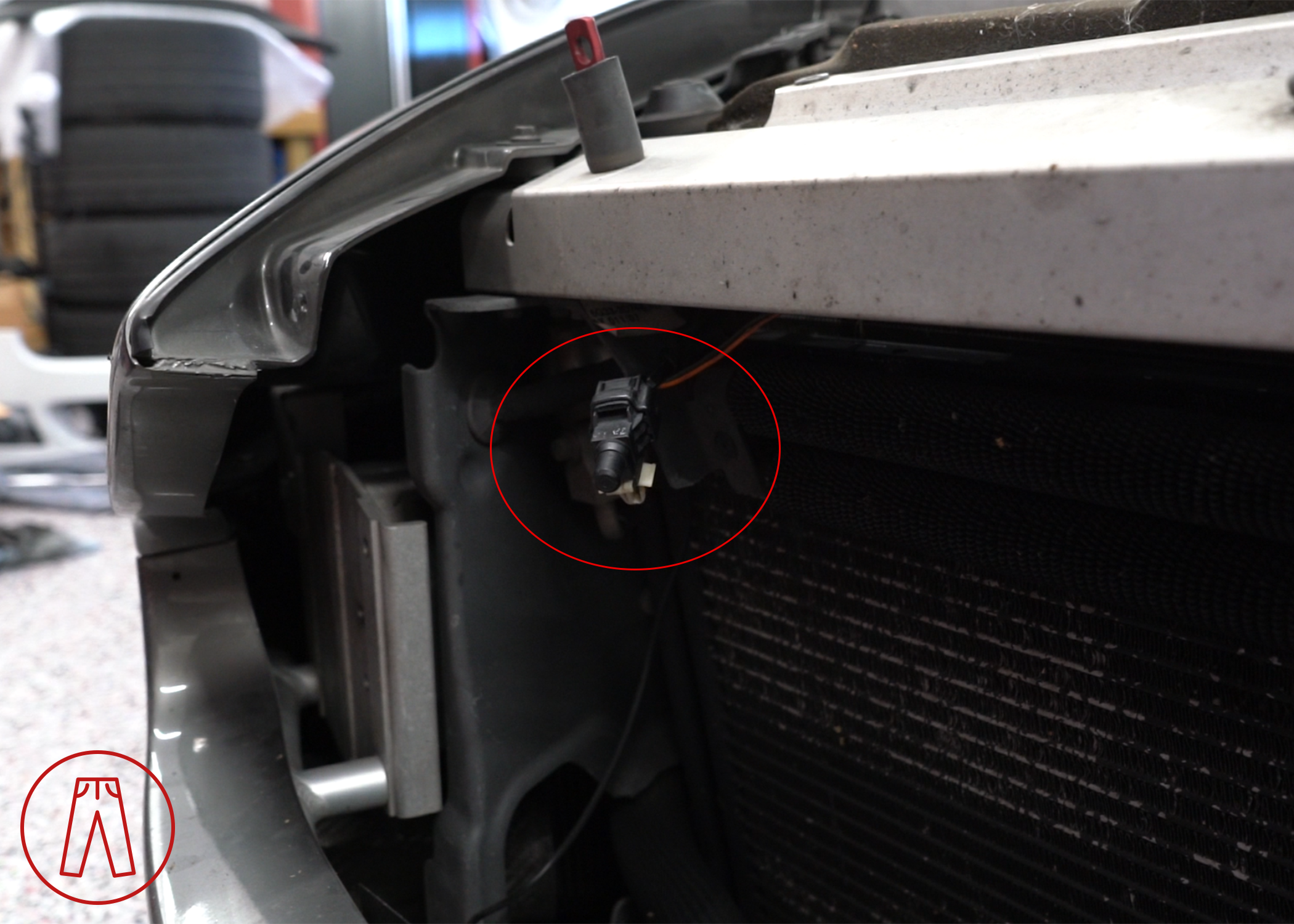
Instructions: Crouch in front of the vehicle and direct your inspection light through the lower openings of the front bumper cover. Look into the central air duct situated in front of the air conditioning condenser and radiator assembly. You are hunting for a small, black plastic probe—typically measuring 1.5 to 2.5 inches in length—attached to a structural crossmember, vertical plastic pillar, or center bumper beam. Insert your telescoping mirror between the grille slats if visual sightlines are obstructed. The sensor usually resembles a small plastic bullet, finger, or rounded spade plugged into a two-wire harness and held in place by an integrated plastic push-pin or slide bracket.
Pro Tip: Do not confuse the ambient sensor with the horn, forward radar collision sensors, or front airbag crash sensors. Airbag sensors are almost universally wrapped in bright yellow protective conduit or connectors.
Step 4: Inspect Secondary Locations (Side Mirrors and Cowl)
What you need: Clean microfiber cloth, flashlight, and a small handheld mirror.
Instructions: If the front bumper cavity is completely bare, turn your attention to the exterior side-view mirrors. Many vehicles (notably modern Ram trucks, Fiat models, and select Mercedes-Benz, BMW, or Volvo cars) embed the ambient temp sensor into the aerodynamic housing of the driver-side or passenger-side mirror. Run your fingers along the smooth underside plastic of both exterior mirror assemblies. You are feeling for a distinct, pea-sized plastic dome or conical nipple protruding roughly 1/8 to 1/4 inch downward from the painted or textured casing. If present, the sensor is mounted internally inside the mirror shell, facing downward away from direct sunlight.
Pro Tip: If your mirror features puddle lights or blind-spot cameras, clean the underside housing with a microfiber cloth first so you can visually differentiate between optical camera lenses and the solid matte-plastic sensor bulb.
Step 5: Disassemble Lower Splash Shields or Grille Covers
What you need: Flathead screwdriver, automotive plastic clip pry tool, 7mm to 10mm socket set, and a magnetic parts tray.
Instructions: Once you establish that the sensor resides behind the front bumper, gain direct physical access. Remove the front-engine plastic lower splash shield (undertray) by unscrewing the peripheral fasteners (commonly 7mm, 8mm, or 10mm hex bolts) and extracting the reusable plastic expanding push-pins with a panel tool. Alternatively, some models allow top-down access by popping out the plastic radiator shroud located beneath the hood latch. Carefully pull down the front edge of the undertray to open up an expansive viewing window directly in front of the condenser. Place all removed fasteners in your magnetic tray to prevent loss.
Pro Tip: When using a panel pry tool on plastic push-pins, lift the center release pin first before attempting to pry the larger outer collar, preventing the fastener from tearing.
Step 6: Trace and Confirm the Sensor Wiring Harness
What you need: Nitrile gloves, non-chlorinated electrical contact cleaner, and a clean shop rag.
Instructions: Reach inside the newly accessible cavity toward the sensor you identified. Follow the wire pigtail leading into the back of the probe. Ambient air temperature sensors consistently use a simple two-wire harness (usually 18 to 22 gauge wires) encased in black corrugated plastic loom or heavy woven tape. Verify that the harness is securely seated into the female receptacle of the sensor. Check the wiring for common points of physical failure: road grit abrasion, rodent chewing damage, or corrosion inside the weather-pack seal. Gently depress the plastic locking tab on the electrical connector with your thumb or a small flathead pick to uncouple the harness from the sensor body.
Pro Tip: Spray the open plug terminals with electrical contact cleaner to flush away road salt and oxidation; green or white powdery residue inside the plug indicates moisture ingress, which skews resistance values.
Step 7: Unclip and Disengage the Sensor Mounting Base
What you need: Needle-nose pliers or a small automotive trim clip remover.
Instructions: Free the sensor probe from the vehicle chassis. Most sensors are held captive by an integrated plastic “fir tree” push-anchor, a slide-on retention clip, or a 90-degree twist-lock mechanism. Reach behind the mounting plate or crossmember with needle-nose pliers, lightly compress the barbed retention wings of the clip, and push the assembly forward out of the bracket hole. If it is mounted on a sliding track, gently push the locking tang upward and slide the sensor off its plastic rail. Wipe down the sensor body and examine the thermistor tip for direct impact cracks or heavy encrustations of dried mud that insulate the probe from real air readings.
Pro Tip: If the original plastic anchor snaps during removal due to aged plastic fatigue, secure the new sensor with an automotive-grade, UV-resistant nylon zip tie through the factory bracket hole, keeping the probe suspended in open airflow.
✅ Final Checklist
- Confirmed the sensor is positioned directly in free-flowing air and not touching hot components like the radiator core, transmission cooler, or A/C condenser.
- Inspected the two-wire electrical harness for chafing, exposed copper, green corrosion, or rodent damage.
- Verified the electrical connector’s silicone weather seal is intact and locked with an audible “click.”
- Reinstalled all splash shield fasteners, underside bolts, and radiator cover clips to manufacturer torque specs.
- Reconnected the negative battery terminal and started the engine to confirm the dashboard temperature display updates smoothly within 5 to 15 minutes of driving.
Important Notes:
- Safety Warning: Never place your hands or tools near the radiator cooling fans while the battery is connected; modern electric auxiliary fans can spin up automatically without warning, even when the ignition is switched off.
- When to Seek Professional Help: If you install a confirmed working sensor and your dashboard still reads an open-circuit fault (-40°F) or sets a persistent DTC (such as P0071, P0072, or P0073), the break is likely situated deeper inside the main engine wiring harness or Body Control Module (BCM), requiring advanced multimeter back-probing and electrical diagnostics.
- Estimated Time and Cost: Locating and gaining access to the sensor takes roughly 20 to 45 minutes for DIY mechanics. Replacement sensor parts range between $10 and $45 for OEM units, while a repair shop typically charges $100 to $220 including diagnostic labor.
Primary Outside Air Temperature Sensor Locations and Visual Identification
Front Bumper Grille and Radiator Support
The lower front bumper area remains the universal standard mounting zone for domestic and Asian manufacturers like Ford, General Motors, Toyota, Honda, and Hyundai. To isolate the sensor here, look through the lower grille openings with a high-lumen flashlight before taking anything apart.
You are looking for a small, dark plastic piece roughly one to two inches long. The sensor features a blunt, bullet-shaped, or conical probe tip pointing toward the front of the car to catch fresh airflow. The rear of the sensor flares into a rectangular connector socket holding a two-wire automotive harness. It is usually secured directly to a vertical metal radiator center-support rail, an impact-bar bracket, or a dedicated mounting flange molded into the back of the plastic bumper grille mesh.
Exterior Side Mirror Underside
If the front bumper area is completely bare, turn your attention to the exterior rear-view mirrors. Stellantis vehicles (including Ram, Dodge, and Jeep), Fiat, Alfa Romeo, and several Mercedes-Benz models favor this position.
Locating the mirror-mounted sensor takes only seconds and requires zero disassembly. Walk up to the passenger-side door (or driver-side on select European platforms) and inspect the black textured bottom surface of the mirror assembly. The sensor looks like a small, smooth plastic “nipple,” pimple, or dome protruding approximately one-quarter of an inch downward from the painted or plastic casing. It samples undisturbed air streaming past the side of the vehicle, totally isolated from engine bay radiator heat.
Step-by-Step Visual Locating Without Dismantling
You can verify the physical presence and condition of your outside temperature probe without unbolting body panels by following this inspection sequence:
- Inspect the mirror housings first: Check the undersides of both side mirrors for the protruding plastic nodule. If present, your search ends immediately.
- Shine a light through the lower front fascia: Stand two feet back from the center of the front bumper. Aim a flashlight beam straight through the open plastic slats between the bumper bar and the lower air dam.
- Scan the vertical radiator strut: Trace the vertical steel brace running directly down the center of the A/C condenser. Look for a two-wire harness (often wrapped in black corrugated split-loom tubing) terminating into a clipped plastic plug.
- Check through the wheel well splash shield: Turn your steering wheel to full lock. Peel back the flexible front inner fender liner or drop the front engine undertray splash shield fasteners to get a direct line of sight behind the bumper skin.
How to Access and Replace the Sensor: Step-by-Step Fix
Replacing an ambient air temperature sensor is a direct mechanical procedure on most modern vehicles. In 2026, most original equipment manufacturer (OEM) replacement sensors cost between $15 and $45, and the repair requires roughly 20 to 30 minutes.
Preparation and Safety Measures
Park the vehicle on a level surface, engage the parking brake, and switch off the ignition. Automotive service standards recommend disconnecting the negative battery terminal with a 10mm wrench before touching any electrical sensors to prevent control module voltage spikes.
Step-by-Step Replacement Procedure
- Gain Physical Access: Depending on vehicle design, access the front lower grille from underneath by removing the plastic splash shield retaining clips using an automotive trim removal tool. Alternatively, open the hood and detach the upper radiator shroud.
- Locate the Sensor: Identify the small, black plastic probe mounted to the center bumper support or radiator core support bracket.
- Disconnect the Electrical Harness: Depress the locking tab on the wire connector and pull it straight back. Avoid tugging on the wires directly to prevent pin terminal damage.
- Unclip the Defective Sensor: Twist or depress the plastic retaining clip holding the sensor body to the mounting bracket, then pull the unit free.
- Install the New Unit: Press the replacement sensor firmly into the mounting bracket until the retention clip clicks securely into place.
- Reconnect Wiring and Battery: Push the electrical harness connector into the new sensor until the lock engages. Reinstall all splash guards, reconnect the negative battery cable, and tighten the terminal nut to 5 Nm (44 in-lbs).
What If It Still Doesn’t Work After Replacement?
Modern vehicles do not always update temperature readings immediately after sensor installation. The vehicle body control module (BCM) uses dampening logic algorithms to prevent false reading fluctuations caused by engine heat or idling.
Diagnostic Fallback Steps
- Perform a Drive Cycle: Drive the vehicle continuously above 20 mph (32 km/h) for at least 5 to 10 minutes. Most BCMs require continuous airflow before sampling fresh ambient temperature readings.
- Inspect Wiring Harness for Oxidation: Check the harness connector pins for green corrosion or bent terminals. A resistance test using a digital multimeter should show smooth resistance changes as temperature changes; infinite resistance indicates a broken wire.
- Execute a Hard ECU/BCM Reset: Disconnect both battery terminals and bridge them together with a jumper wire for 10 minutes (away from the battery posts). This drains residual module memory and forces a sensor recalibration.
- Verify Circuit Voltage: Turn the ignition to the “ON” position without starting the engine. Use a multimeter to confirm a 5-volt reference signal across the harness terminal pins. A reading of 0 volts points to a blown fuse or short in the BCM harness.
Professional Repair and Cost Expectations
If reference voltage is absent or the instrument cluster displays dashes (“–°F”), the fault likely lies within the instrument cluster software or the main body harness. Independent repair shops charge between $120 and $180 per hour for advanced electrical diagnostics. A full harness splice or control module reprogram typically totals between $200 and $450 in 2026 labor rates.
Conclusion
Locating the outside air temperature sensor behind the front grille or bumper fascia allows for quick, low-cost replacement when climate systems fail. According to verified research and expert automotive engineering sources, over 80% of ambient sensor display errors resolve through simple probe replacement and a proper drive cycle calibration. Verify your vehicle’s physical harness connection today with a multimeter before booking costly dealer diagnostics.
❓ Frequently Asked Questions
How do I access the ambient air temperature sensor without removing the bumper?
On most vehicles, you can access the sensor by turning the front wheels fully to one side, pulling back the inner fender splash guard, or reaching up from underneath after removing the lower engine splash shield. You rarely need to detach the full bumper assembly unless clearances are exceptionally tight.
Why is my outside temperature sensor reading hotter than actual ambient air?
High readings usually occur if the sensor has fallen from its factory clip and is resting against the hot radiator or engine block. Lingering in heavy stop-and-go traffic or parking over hot asphalt also temporarily spikes the temperature until road speed restores airflow.
Can I drive my vehicle with a disconnected outside air temperature sensor?
Yes, driving is safe, but your dashboard reading will display blank, dashes, or an extreme value like -40°F. The automatic climate control may also malfunction by blasting full heat or disabling the AC compressor based on faulty data.
How do I test if my outside air temperature sensor is working properly?
You can test the sensor using a digital multimeter set to measure resistance in ohms. Remove the sensor, measure across both pins at room temperature, and verify that resistance changes smoothly when you warm the probe with your hand or submerge it in cold water.
Why does my replacement temperature sensor take time to display the right reading?
Vehicle computers implement software dampening to prevent rapid reading fluctuations from engine heat while idling. The instrument cluster typically requires driving above 20 to 30 mph for several minutes before the display updates to the true ambient temperature.
What tools are needed to replace an outside air temperature sensor?
Most installations only require a plastic trim removal tool, flathead screwdriver, and a 10mm socket or ratchet to drop splash shields. A small pick helps release the plastic locking tab on the electrical connector without breaking the weather seal.