2001 Toyota Tacoma Parts Diagram: 2026 Component Breakdown

The 2001 Toyota Tacoma parts diagram maps structural, powertrain, and electrical assemblies across 2.4L (2RZ-FE), 2.7L (3RZ-FE), and 3.4L (5VZ-FE) configurations. It details subsystem layouts including front double-wishbone suspension linkages, frame-rail mounting points, and vacuum routing schematics, indexing exploded callout numbers directly to factory OEM part codes for accurate disassembly and replacement.
📌 Key Takeaways
- Front lower ball joints use four grade-10.9 bolts torqued to 59 lb-ft with blue threadlocker.
- VIN positions 4-8 distinguish between 2WD base, PreRunner, and 4WD 5VZ-FE/3RZ-FE chassis configurations.
- Exploded schematics follow standard Toyota 5-digit primary group and 5-digit component numbering schemes.
- The leading mechanical failure point involves lower ball joint separation and rear frame rail rust perforation.
- Bolt-on component replacement is DIY-accessible, but structural frame section repairs require certified automotive welders.
Navigating a 2001 Toyota Tacoma parts diagram requires understanding the mid-cycle platform revisions that Toyota introduced for the 2001 model year. As the midpoint of the first-generation production cycle (1995.5–2004), the 2001 model introduced significant chassis additions, electrical updates, and front-end sheet metal changes. Whether you are rebuilding a 5VZ-FE cylinder head, overhauling a worn steering rack, or sourcing front suspension components for a PreRunner, relying on generic schematics often leads to incorrect part orders. This technical reference breaks down the factory catalog layout, decodes Toyota’s Part Name Code (PNC) system, and highlights key mechanical variations across 2001 trim lines.
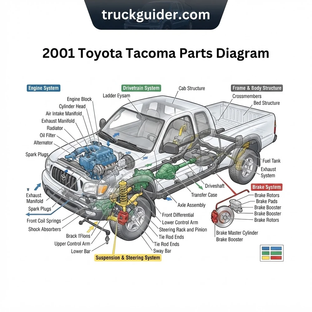
2001 Toyota Tacoma Parts Diagram Layout and Submodel Variations


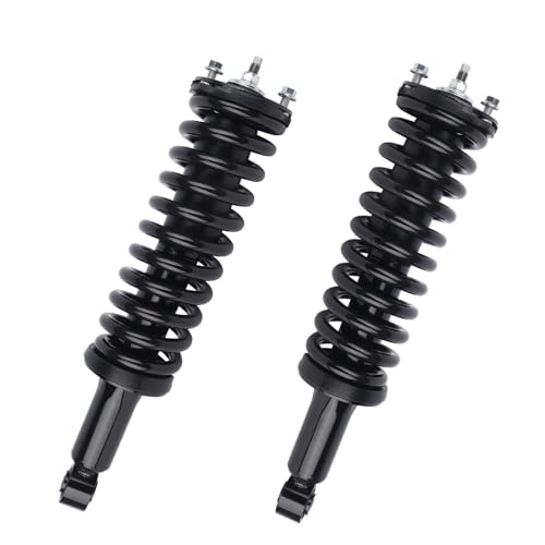

The 2001 model year represents a major inflection point for the first-generation Toyota Tacoma (1995.5–2004). Catalog schematics for 2001 diverge significantly from earlier first-gen years due to two primary developments: the introduction of the four-door Double Cab body configuration and a comprehensive front-clip redesign across all trim lines. When navigating factory schematics, verify your vehicle identification number (VIN) frame prefix before referencing callout sheets to avoid ordering incompatible parts.
The body panels and exterior trim layout underwent substantial structural updates for 2001. Toyota engineered a raised hood profile, an integrated one-piece front fascia, and redesigned headlamp assemblies with revised mounting tab positions. Fenders on wide-body configurations (4WD and Tacoma PreRunner models) feature specific factory punch holes for bolt-on composite fender flares, designated under callout group 53-02. Standard 5-lug base chassis diagrams display smooth, flareless sheet metal with narrower wheelhouse inner aprons. Attempting to interchange 1995–2000 core supports or front fenders with a 2001 schematic will fail; the radiator support crossmember stamping (PNC 53201) was revised to house the updated horizontal-latch grille assembly and altered air-conditioning condenser mounts.
Cab configurations dictate distinct floor pan and frame rail blueprints. The catalog isolates the Tacoma Double Cab platform under distinct body shell codes, featuring a shortened 61.5-inch cargo bed that shifts the rear shock absorber crossmember and fuel tank strap positions relative to Regular Cab and Xtracab variants. The Tacoma PreRunner combines two-wheel-drive propulsion with the 6-lug, high-clearance suspension structure of the four-wheel-drive platform. In parts diagrams, this means PreRunner steering knuckles, control arms, and leaf spring perches are cataloged alongside 4WD running gear (Chassis Group 48-01 and 48-02), while using a distinct rear-wheel-drive transmission output shaft and slip-yoke configuration.
For model year 2001, Toyota replaced mechanical cable-actuated throttle bodies on automatic 5VZ-FE V6 engines with an electronic throttle control system (ETCS-i). Catalogs for 2001 feature distinct accelerator pedal position sensors (PNC 89281) and drive-by-wire throttle actuator diagrams not found on 1995–2000 models.
2001 Toyota Tacoma Parts Diagram Component Breakdown


Understanding the exploded-view structural diagrams across primary mechanical subsystems requires isolating component relationships, fasteners, and fluid-routing interfaces. Factory diagrams organize components into distinct groupings: Tool/Engine/Fuel, Chassis/Transmission, Electrical, and Body.
Front Suspension and Steering Linkage Schematic
The front suspension system differs drastically depending on lug count. The 5-lug base model features a conventional low-slung, double-wishbone configuration with dynamic coil placement, whereas 6-lug PreRunner and 4WD models share a raised coilover-over-shock architecture (Illustration Group 48-02).
On 6-lug chassis, the front steering knuckle attaches to the lower control arm via a high-stress lower ball joint (LBJ) assembly (PNC 43330 for left-hand, 43340 for right-hand). The four LBJ mounting flange bolts (OEM P/N 90119-10933) represent a critical failure point; catalog specs require grade 10.9 factory flanged fasteners tightened to 59 ft-lb with blue thread-locking compound. The rack-and-pinion steering schematic (Group 44-01) routes hydraulic hard lines across the steering rack housing to the intermediate shaft coupling (PNC 45203). Technicians referencing the outer tie-rod end callouts (PNC 45046/45047) must confirm steering knuckle geometry, as 4WD/PreRunner ball-joint taper dimensions measure 17.5 mm compared to the smaller 15.0 mm pin used on 5-lug configurations.
Never reuse the four factory lower ball joint flange bolts during front-end overhauls. 2001 schematics specifically designate these fasteners as one-time-use items prone to shear fatigue if torqued without factory loctite compound.
Engine and Valvetrain Structural Assembly Diagram
The 2001 powertrain lineup includes three distinct engine blueprints: the 2.4L inline-four (2RZ-FE, base 5-lug), the 2.7L inline-four (3RZ-FE, 4WD/PreRunner), and the 3.4L dual-overhead-cam V6 (5VZ-FE, optional across all trims). Diagram section 11-04 covers the 5VZ-FE valvetrain assembly, detailing the double overhead camshaft layout driven by a single toothed timing belt (PNC 13568, OEM P/N 13568-YZZ03).
The timing drive schematic illustrates the hydraulic tensioner assembly (PNC 13540), tensioner idler pulley (PNC 13505), and No. 2 idler pulley (PNC 13503). Cylinder heads (PNC 11101/11102) utilize bucket-and-shim solid lifters directly above 24 valves; individual valve clearance adjustment shims are indexed under standard part number 13753-xxxxx, varying by thickness from 2.50 mm to 3.30 mm in 0.02 mm increments. For bottom-end overhauls, the cast-iron cylinder block blueprint (Group 11-01) outlines the four-bolt crankshaft main bearing caps torqued to 45 ft-lb plus a 90-degree angle turn, interfacing with an oil pan assembly featuring an integrated rear-sump baffle to accommodate the front differential housing clearance on 4WD applications.
Transmission and Transfer Case Breakdown
The transmission and transfer case exploded diagrams isolate torque-transfer components according to operational design. Manual platforms feature either the W59 5-speed transmission (behind four-cylinder engines) or the robust R150F 5-speed transmission (behind the 3.4L V6). Schematics illustrate the bellhousing layout (PNC 31111), input shaft bearing retainer, and the reverse restrictor pin mechanism within the shift tower.
Automatic platforms are governed by the Aisin-Warner A340E (2WD/PreRunner) or A340F (4WD) hydraulic planetary gear assemblies. The internal schematic exposes the valve body separator plate, shift solenoids No. 1 and No. 2 (PNC 35250), and the lock-up clutch control solenoid (PNC 35270). The 4WD transfer case layout (VF1A manual shift or VF2A push-button actuator) splits the drivetrain output via a heavy-duty silent drive chain (PNC 36293). When servicing transfer case seals, refer to group 36-01: front output shaft oil seal (P/N 90311-41007) and rear output shaft oil seal (P/N 90311-40013), each seated within specific precision depths relative to their retaining snap rings.
Transfer case rear output companion flange nut torque specification: 87 ft-lb (118 Nm). Manual transmission drain and fill plug torque: 27 ft-lb (37 Nm); transfer case plugs: 27 ft-lb (37 Nm).
Rear Axle and Leaf Spring Suspension Diagram
The rear running gear diagram (Illustration Group 42-01 and 48-04) maps the rear differential housing and asymmetric leaf spring configuration. In 2001, Toyota utilized two primary rear axle configurations: the 8.0-inch differential with an optional factory electric locking differential (E-locker) and the standard 8.4-inch (2-piece carrier) non-locking differential found on non-TRD Off-Road packages.
The axle housing schematic displays the semi-floating axle shaft shafts (PNC 42311), which are held inside the axle tube via an internal bearing retainer, ABS tone ring, dynamic oil seal (P/N 90310-50006), and a pressed-on lock collar. The leaf spring blueprint shows an offset multi-leaf pack with staggered shock absorber configurations (one shock positioned forward of the axle tube, one mounted aft) to prevent dynamic axle wrap during high-torque load cycles. The U-bolt mounting schematic (PNC 48046) specifies four M14 x 1.5 threaded U-bolts torqued to 90 ft-lb, clamping the leaf bundle to the spring seat via the lower spring clamp bracket.
How to Read a 2001 Toyota Tacoma Parts Schematic Step by Step


Decoding a manufacturer technical drawing requires translating visual exploded-view references into orderable part numbers. Follow these standardized diagnostic steps to isolate components within the official Toyota Electronic Parts Catalog (EPC):
1. Locate and Decode the Vehicle Identification Plate
Before opening catalog software, read the production stamping on the driver-side door jamb placard. Note the complete 17-digit VIN, the Model Code (e.g., VZN170L-DKPDKAB), the Engine Family (5VZ-FE), and the Transmission/Axle Code (such as A340F / B03A). The axle code indicates ring gear diameter and pinion gear tooth count, which determines the differential schematic required.
2. Identify the Target Primary Group and Illustration
Open the catalog to the primary functional division. System groups are indexed into standardized categories:
• Group 1: Engine, fuel supply, water pump, and exhaust system
• Group 2: Transmission, clutch, and transfer case
• Group 3: Propeller shaft, front/rear axles, brake lines, and steering
• Group 4: Frame rails, body mounts, cab panels, and suspension linkage
• Group 5: Electrical harness routing, sensors, ECU, lighting, and switches
3. Locate the Part Name Code (PNC) Callout Number
Navigate the assembly blueprint to identify the target part. Schematics do not show complete 10-digit part numbers on the drawing face. Instead, they use a 5-digit Part Name Code (PNC) or Callout Number. For example, if you are sourcing an engine water pump on a 3.4L V6, the diagram points to callout 16100. If you are locating the upstream bank 1 air-fuel ratio sensor, the diagram points to callout 89467.
4. Cross-Reference the PNC Against the Data Table
Select the 5-digit callout number to open the corresponding part list index. The catalog cross-references the callout against your vehicle’s specific production date, frame series, and factory options. For example, selecting callout 16100 displays the full 10-digit original equipment part number: 16100-69398-83.
5. Verify Superseded Part Numbers and Production Breaks
Check the parts listing for supersession markers. Toyota frequently updates manufacturing specifications, resulting in a superseded part number. If your 2001 diagram displays an original part number that has been discontinued, the catalog will indicate the modern authorized replacement. For instance, early 2001 ignition coils (90919-02212) cross-reference directly to the modernized factory replacement unit (90919-02234). Take special note of mid-year production breaks (e.g., “08/2000-09/2001” vs “10/2001-08/2004”), which indicate running engineering changes.
| System Assembly | PNC (Callout) | OEM Part Number | Technical Function |
|---|---|---|---|
| 5VZ-FE Engine | 13568 | 13568-YZZ03 | Timing Belt (Valvetrain Synchronizer) |
| Front Suspension | 43330 | 43330-39585 | Lower Ball Joint Assembly (LH, 4WD/PreRunner) |
| Front Suspension | 43340 | 43340-39465 | Lower Ball Joint Assembly (RH, 4WD/PreRunner) |
| Fuel & Emissions | 89467 | 89467-35011 | Upstream Air/Fuel Ratio Sensor (California Spec) |
| Rear Axle | 90310 | 90310-50006 | Rear Axle Shaft Inner Oil Seal |
Troubleshooting 2001 Toyota Tacoma Diagram Errors and Misordered Parts



Parts ordering errors on the 2001 platform occur frequently because technicians often rely on visual similarity rather than verifying trim codes. One common issue involves cross-referencing between a 2000 Toyota Tacoma parts diagram and the 2001 manual. While the trucks look structurally similar from the doors back, the emissions architecture changed nationwide for the 2001 model year.
Prior to 2001, federal emissions vehicles used a single catalytic converter and standard oxygen sensors (PNC 89465). For 2001, all 5VZ-FE platforms adopted a dual-catalytic converter exhaust system featuring an upstream heated Air/Fuel (A/F) ratio wideband sensor (PNC 89467) alongside a downstream O2 sensor. Ordering an upstream oxygen sensor from a 2000 blueprint results in erratic fuel trim codes (P0171) and sensor thread mismatch, as early sensors utilize a two-bolt diamond flange mounting bracket while the 2001 sensor incorporates a threaded M18 x 1.5 bung.
A related issue occurs when ordering components for the Tacoma PreRunner. Because the PreRunner sits at the same ride height as a 4WD model, technicians often mistakenly order 4WD drivetrain components. The PreRunner front hub schematic displays a dummy spindle plug and sealed wheel bearing hub, whereas the 4WD blueprint features dynamic CV axle splines, intermediate front drive axles (PNC 43430), and differential disconnect actuators. If you need front-end parts for a PreRunner, consult the 4WD suspension diagrams for control arms, struts, and sway bars, but switch to 2WD catalog trees for front wheel bearings, hub lock plates, and transmission assemblies.
You must also exercise caution when using a 1996–2002 Toyota 4Runner parts diagram to source replacement components. Although third-generation 4Runners share the 5VZ-FE powertrain and front suspension architecture with the Tacoma, the rear chassis is fundamentally different. The 4Runner utilizes a coil-sprung, 4-link rear axle setup with a panhard lateral control rod (PNC 48706). Tacomas use a semi-elliptic leaf spring suspension with axle-tube-mounted damper plates. Ordering rear suspension bushings, shocks, or axle housings from a 4Runner schematic will yield parts that cannot be installed on a Tacoma chassis.
Finally, avoid referencing next-generation documentation. A 2005 Toyota Tacoma parts diagram covers the larger second-generation platform (GRN220/240 series). Second-generation Tacomas utilize 4.0L 1GR-FE engines, 6-speed manual transmissions, and an entirely different chassis width, rendering all frame, suspension, and engine callouts incompatible with the 2001 truck.
2001 Toyota Tacoma Submodel Configuration and Chassis Matrix
The matrix below highlights mechanical and chassis variations across 2001 model lines. Use these engineering designations to cross-reference your door jamb data plate with the correct parts catalog tree.
| Submodel & Drive | Lug Pattern & Front Geometry | OEM Engine Options | Factory Transmission Options | Rear Differential Architecture |
|---|---|---|---|---|
| Base Regular/Xtracab 2WD | 5-Lug (5×114.3mm) / Low-Profile Double Wishbone | 2.4L I4 (2RZ-FE) | 5-Speed Man (W59) / 4-Speed Auto (A43D/A340E) | 7.5-Inch Standard Open Carrier |
| Tacoma PreRunner (All Cabs) | 6-Lug (6×139.7mm) / High-Clearance Coilover Double Wishbone | 2.7L I4 (3RZ-FE) / 3.4L V6 (5VZ-FE) | 4-Speed Automatic (A340E) | 8.4-Inch Open or 8.0-Inch E-Locker |
| Tacoma 4WD (All Cabs) | 6-Lug (6×139.7mm) / High-Clearance Coilover Double Wishbone | 2.7L I4 (3RZ-FE) / 3.4L V6 (5VZ-FE) | 5-Speed Man (W59/R150F) / 4-Speed Auto (A340F) | 8.4-Inch Open or 8.0-Inch E-Locker |
| Tacoma S-Runner Xtracab | 5-Lug (5×114.3mm) / Sport Tuned + Factory Swaybars | 3.4L V6 (5VZ-FE) | 5-Speed Manual (R150) | 7.5-Inch Differential with 3.15:1 Ratio |
2001 Toyota Tacoma Technical Blueprint and Schematic FAQ
How do I identify which 2001 Toyota Tacoma parts diagram covers my rear differential?
To pinpoint the correct differential diagram, read the axle code stamped on your vehicle identification label located inside the driver-side door jamb. A code beginning with “B” (such as B03A) signifies an 8.0-inch differential ring gear—which corresponds to the factory electric-locking carrier assembly found on TRD Off-Road packages. If your axle code begins with “A” (such as A01A or A02A), your truck is equipped with the 8.4-inch (actually 8.0-inch cross-pin with bearing cap girdle) differential assembly without a locking mechanism. Look for the presence of the differential actuator callout (PNC 41450) on the schematic to verify whether you are viewing the E-locker or non-locker exploded view.
Why do 2001 Tacoma parts diagrams list different lower ball joints for the same model year?
Toyota catalog schematics divide lower ball joints into two configurations: 5-lug base platforms and 6-lug platforms (Tacoma PreRunner and 4WD). The 5-lug trucks use a traditional compression-loaded lower joint (PNC 43330-39315), while 6-lug variants use a larger tension-loaded design (PNC 43330-39585 left-hand, 43340-39465 right-hand). In late 2001, Toyota revised the metallurgy and ball-stud casting thickness across 6-lug designs to enhance joint durability, resulting in a part number update. When viewing the catalog, always filter by your specific VIN to ensure you select the updated assembly along with the required high-tensile mounting hardware (P/N 90119-10933).
Where can I find the correct wiring harness diagram for my 2001 Tacoma throttle body?
Throttle body wiring schematics are cataloged under Electrical Group 84-01 (Switch & Relay) and Group 82-02 (Wiring & Clamp). For the 2001 model year, V6 automatic models transitioned to the ETCS-i semi-drive-by-wire system. This harness includes connections for the throttle control motor (terminal connections pin 1 motor positive, pin 2 motor negative) and a four-wire throttle position sensor (PNC 89452). Manual transmission models and 4-cylinder trucks retained pure mechanical cable throttles, which are documented under distinct wire routing diagrams that do not include the dynamic throttle clutch relay or motor harness pigtails.
Can I use front bumper mounting brackets from a 1999 Tacoma on a 2001 frame?
No, the frame horn extensions and front bumper mounting brackets are not interchangeable between 1999 and 2001 models. In the 2001 redesign, Toyota altered the frame rail forward crumple zones and extended the forward bumper mounting plate (Illustration Group 52-01, PNC 52115 right-hand, 52116 left-hand). The 2001 bracket configuration utilizes a distinct triangular three-bolt pattern matched to the redesigned front facia profile. Components from a 1999 parts diagram will not align with the 2001 core support or frame holes without fabrication.
Step-by-Step Guide to Understanding the 2001 Toyota Tacoma Parts Diagram
Identify – Determine your Tacoma sub-model, engine code (2.4L, 2.7L, or 3.4L), and drive system configuration using the driver-side door jamb VIN tag.
Locate – Find the specific subsystem section in the master parts manual, isolating the primary assembly and surrounding hardware.
Reference – Trace the numbered callout balloons on the exploded schematic to confirm exact fastener sizes, bracket locations, and gasket orientations.
Connect/Route – Assemble or route components according to the diagram’s visual sequence, taking care to duplicate factory harness clips and vacuum line layouts.
Verify – Cross-check installed hardware against factory torque specifications, ensuring all pins, clips, and fluid seals seat flush without pinching.
Troubleshoot – Inspect mounting points for misalignment, interference, or remaining unused hardware if the assembled configuration binds or leaks during testing.