2002 Ford F150 Heater Hose Diagram: Routing & Repair (2026)

The 2002 Ford F150 heater hose system routes pressurized coolant from the engine water crossover tube directly to the lower heater core inlet tube. The return hose runs from the upper heater core outlet tube along the passenger side valve cover back to the water pump inlet pipe, utilizing plastic quick-disconnect fittings at the firewall.
📌 Key Takeaways
- Factory quick-disconnect fittings use 5/8-inch and 3/4-inch connector couplings at the firewall bulkhead.
- Inlet hose supplies hot coolant from the engine intake crossover to the bottom heater core nipple.
- Cooling system operating pressure runs between 13 and 16 PSI under normal conditions.
- Plastic quick-connect clips become brittle from engine heat and represent the primary coolant leak point.
- Standard hose replacement is DIY-friendly, but rotted metal under-manifold return tubes may require professional labor.
The heating, ventilation, and air conditioning (HVAC) thermal exchange circuit on the tenth-generation 2002 Ford F-150 (PN-96 platform) relies on a closed-loop coolant circuit routed from the engine block to the passenger-side cabin bulkhead. Operating under system pressures up to 16 psi (110 kPa), this cooling network supplies hot engine coolant to the cabin heater core while maintaining thermal stabilization across the cylinder heads. Understanding the routing, connection interfaces, and internal restrictors of the 2002 Ford F150 heater hose diagram is essential for troubleshooting cabin heat loss, chronic coolant consumption, or elusive leaks pooling within the engine valley.
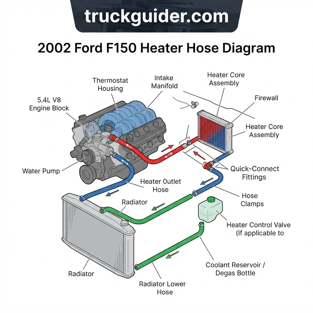
2002 Ford F150 Heater Hose Diagram: V8 and V6 Routing Schematics


The structural layout of the 2002 F-150 heater circuit varies significantly between the Essex V6 and the Modular Triton V8 platforms. Navigating the 2002 Ford F150 heater hose diagram requires verifying your vehicle’s engine displacement, as coolant tap locations and return passages differ mechanically between the two architectures.
On the 4.6L (VIN 6 or W) and 5.4L (VIN L) Triton V8 engines, the supply circuit initiates at the passenger-side front coolant crossover pipe integrated into the intake manifold assembly. Pressurized, un-thermostatted coolant exits the manifold passage through a dedicated metal nipple or threaded adapter, routing directly into the 5/8-inch inside diameter (ID) heater core inlet hose. This molded line travels rearward along the passenger-side valve cover, negotiating clearance gaps around the fuel rail, ignition coil harnesses, and the transmission dipstick tube, before terminating at the lower bulkhead quick-disconnect fitting on the firewall.
The return circuit on the Modular V8 engines follows a specialized under-manifold configuration. Coolant leaves the upper heater core firewall connection through the 3/4-inch ID outlet hose. Rather than routing directly back to the front radiator tank, this line snaps onto a rigid steel valley bypass tube located behind the cylinder head. This valley pipe runs forward beneath the composite intake manifold runners inside the engine block’s “V” groove, sealing directly into the backside of the water pump housing via dual slip-fit O-rings. This internal return channel shields the return path from external impact but introduces hidden failure points if corrosion or seal degradation occurs.
In contrast, the 4.2L Essex V6 (VIN 2) employs a completely exposed exterior layout. Coolant supply departs from a bypass nipple located adjacent to the thermostat housing on the front water outlet casting. The 5/8-inch supply line arcs over the passenger valve cover directly to the heater core. The 3/4-inch return line exits the firewall and descends along the lower front passenger side of the engine block, attaching directly to a formed inlet tube on the lower radiator hose junction or water pump intake fitting. The 4.2L design eliminates the hidden under-manifold valley pipe entirely, concentrating all service points and clamp interfaces within the accessible engine bay perimeter.
Modular 4.6L and 5.4L 2-valve engines transitioned from all-aluminum intake manifolds to composite (nylon 6,6) manifolds with an aluminum front crossover starting in the 1999–2000 model years. For 2002 models, verify whether your intake crossover nipple is pressed steel or cast aluminum, as replacement hose clamp torque must not crush fatigued composite mounting bases nearby.
2002 Ford F150 Heater Hose Diagram: Key System Components


To interpret the system blueprint effectively, technicians must recognize the role, dimensional tolerances, and operating thresholds of each part in the assembly. The table below outlines the primary functional components specified across the 2002 Ford F-150 heating loop.
| Component Name | OEM / Reference Part | Dimensions & Materials | Functional Routing / Role |
|---|---|---|---|
| Heater Core Inlet Hose | Motorcraft KH-166 / 2L3Z-18472-AA | 5/8 in. (16 mm) ID; Formed EPDM rubber | Carries hot pressurized coolant from intake crossover to lower heater core firewall nipple. |
| Heater Core Outlet Hose | Motorcraft KH-167 / 2L3Z-18472-BA | 3/4 in. (19 mm) ID; Formed EPDM rubber | Directs chilled return coolant from upper firewall nipple to the engine valley return pipe. |
| Engine Valley Return Tube | Ford 2L1Z-18B402-A / XL3Z-18B402-AA | Tubular coated steel; Dual Viton O-rings | Modular V8 bypass conduit running beneath intake manifold into rear water pump cavity. |
| Quick-Disconnect Couplers | Ford 800-403 (Inlet) / 800-404 (Outlet) | Glass-filled nylon with internal EPDM seals | Spring-clip female fittings coupling molded lines to fragile aluminum cabin bulkhead stubs. |
| In-Line Flow Restrictor | Internal to OEM Supply Hose | 0.280 in. (7.1 mm) orifice; Delrin / Brass | Dampens pressure spikes to protect the heater core from hydraulic burst at high RPM. |
The heater core inlet hose carries the highest thermal load in the circuit. Manufactured from electrochemical-degradation-resistant (ECR) synthetic EPDM, it incorporates internal synthetic fiber reinforcement designed to withstand continuous temperatures of 257°F (125°C). The 5/8-inch line establishes positive coolant delivery to the heat exchanger inside the passenger HVAC plenum box.
The heater core outlet hose transitions the return stream into the water pump suction side via a larger 3/4-inch ID profile. This diameter differential promotes a minimal pressure drop across the heater core matrix, maximizing flow velocity while preventing localized stagnation. On 4.6L and 5.4L engines, the connection between this outlet hose and the rigid valley pipe is secured via a constant-tension spring band clamp, preventing clamp-induced rubber extrusion under cold-soak cycles.
Quick-disconnect fittings simplify assembly line production but introduce critical maintenance considerations on older trucks. These modular fittings contain four internal spring tabs and dual EPDM O-rings nested inside an injection-molded nylon body. When pushed over the beaded lip of the 0.035-inch-wall aluminum heater core tubes, the internal clips snap over the outer bead, locking the hose axially without transferring rotational torque to the heater core tank seams.
Servicing 2002 F-150 Heater Hoses and Quick Disconnect Couplers


Servicing the plumbing on the 2002 Ford F150 heater hose diagram requires strict adherence to removal techniques. The aluminum heater core stubs projecting through the firewall sheet metal are easily deformed; applying excessive bending force will fracture the heater core brazing, necessitating a 10-hour instrument panel tear-down.
- System Depressurization and Drain: Ensure the engine is fully cold. Remove the degas bottle cap slowly to vent residual air pressure. Position a clean fluid catch basin beneath the lower radiator draincock on the passenger-side plastic tank. Attach a 3/8-inch ID clear hose to the drain petcock, open the valve counterclockwise, and extract approximately 4 to 6 quarts (3.8 to 5.7 liters) of coolant to drop the fluid level below the cylinder head plane.
- Disengaging Firewall Quick-Disconnect Fittings: Clean road grime from the exterior of the white/black plastic quick-disconnect collars at the firewall. Insert an angled heater hose disconnect tool (Ford tool 303-315, Lisle 39400, or equivalent 5/8-inch / 3/4-inch specialty release collar) between the plastic connector housing and the metal tube flare. Push the tool firmly into the connector body to depress the four internal retaining fingers. While applying continuous axial pressure on the release tool, gently slide the hose connector straight back off the aluminum tube. Do not twist or rock the plastic fitting laterally.
- Decoupling Engine Connections: On the front intake crossover and the rear valley pipe connections, use constant-tension hose clamp pliers (such as OTC 4525) to lock open the factory spring band clamps. Slide the clamps approximately 3 inches back onto the hose body. If the rubber has vulcanized to the underlying aluminum or steel fittings, use an angled hose pick to break the bond around the inner perimeter. Avoid slicing through the hose with a razor knife over aluminum fittings, as scored metal yields permanent weep channels.
- Installing Pre-Formed Replacement Hoses: Coat the internal O-rings of the new quick-disconnect assemblies with clean, silicate-free ethylene glycol coolant or technical-grade silicone lubricant (Dow Corning 111). Never apply petroleum-based grease, which degrades EPDM rubber seals. Align the connector parallel to the heater core stub and push firmly until an audible click confirms that the internal stainless steel spring lock has seated behind the retention bead. Tug outward lightly to verify axial engagement.
- Torquing and Securing Engine Connections: Slip the forward ends over their respective ports. Position constant-tension spring band clamps exactly within the alignment paint marks imprinted on OEM-style replacement hoses, ensuring clamp tabs clear ignition harnesses, the fuel rail pulse damper, and vacuum lines.
- Coolant Bleed and Air Evacuation: Refill the cooling system through the degas bottle with a 50/50 mixture of Motorcraft Premium Gold coolant (specification WSS-M97B51-A1) and distilled water. Connect a vacuum filling apparatus (e.g., Airlift 550000) or install a spill-free funnel to the reservoir. Start the engine, run it at 1,500 RPM until the thermostat reaches opening temperature (192°F / 89°C), verified by heat radiating through the upper radiator hose. Verify full cabin heat output from the climate vents, run the engine until air bubbling ceases entirely, and inspect all four connection points for trace weeping.
Do not pry against the plastic HVAC casing or the sheet metal firewall using screwdrivers when disconnecting frozen couplers. The aluminum heater core inlet/outlet tubes have a wall thickness of less than 1 mm; bending or distorting them out of round guarantees persistent fluid leaks that standard O-rings cannot seal.
Troubleshooting Common 2002 Ford F150 Heater Hose Leaks and Failures


Diagnosing fluid loss across the 2002 Ford F150 heater hose diagram requires isolating subtle connection failures from broader mechanical faults. A frequent issue on 4.6L and 5.4L Modular engines involves fluid collecting inside the engine valley cavity, often misdiagnosed as an external cylinder head gasket failure or an intake manifold rupture.
The rigid valley bypass tube running beneath the intake manifold is exposed to high thermal cycling. The forward end of this tube seats into the rear water pump casing through an aluminum port sealed by two high-temperature Viton O-rings. Over time, engine vibrations and thermal degradation cause these O-rings to flatten and lose elasticity. Coolant seeps past the seals, runs backward along the engine block valley beneath the lower intake runners, and drains through weep holes at the rear of the bellhousing. When observing coolant dripping off the starter motor or down the rear face of the transmission casing, apply 15 psi (103 kPa) via a cooling system pressure tester. Use an inspection borescope beneath the intake manifold runner runners to observe the valley tube before committing to head gasket replacement.
A second common point of failure occurs at the heater core quick-disconnect couplers. The glass-reinforced nylon shells become brittle after decades of heat exposure under the hood. Micro-cracks develop along the seam lines of the release tabs, causing slow pressure leaks that atomize fluid onto the hot exhaust manifold below. This generates an intermittent sweet coolant vapor smell through the cabin air intake without presenting an obvious puddle on the ground. Replace leaking connectors immediately; a sudden complete fracture of the plastic housing can exhaust several gallons of pressurized coolant in seconds, leading to cylinder head warpage.
Cooling system operating pressure: 16 psi (110 kPa) nominal cap rating. Valley bypass tube O-ring dimensions: 19 mm ID, 25 mm OD, 3 mm cross-section thickness (Motorcraft part # F75Z-8507-AA or generic AS568-210 Viton 75-durometer rings).
Inspect the internal flow restrictor if your truck experiences repeated heater core failures or cold-idle conditions. If an aftermarket straight hose lacks this restrictor, excessive flow velocities erode the internal aluminum baffle plates within the core, causing premature core rupture. Conversely, if aftermarket scale or rust debris breaks loose, it accumulates directly in front of the narrow 0.280-inch restrictor orifice, causing the cabin air to run cold while the engine runs at normal operating temperature.
Heater Hose Configuration: Molded Assemblies vs Bulk Lines
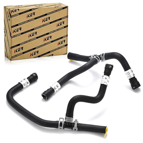
Using bulk, straight heater hose from a generic reel to plumb the 2002 Ford F150 heater circuit creates severe operational risks. The spatial configuration between the engine block, transmission dipstick, harness brackets, and cabin bulkhead features multiple sharp 90-degree and 45-degree bends that bulk flexible hose cannot duplicate without severe kinking.
When straight standard bulk hose is bent across the 5-inch radius required behind the passenger cylinder head, the inner diameter collapses, constricting flow by up to 80%. This reduction halts adequate thermal transfer to the cabin during idle conditions. Furthermore, bulk straight hose lacks the integrated anti-vibration sleeves and protective heat wraps that shield factory molded lines from rubbing against the sharp sheet metal pinch-welds of the firewall and the transmission bellhousing ribs.
Critically, universal bulk hose does not include the essential in-line flow restrictor pressed into the OEM inlet line (Motorcraft KH-166). Ford Technical Service Bulletins (TSBs) specify this restrictor to limit water pump supply pressure spikes under rapid throttle application. During 4,000+ RPM passing maneuvers, unrestricted hydraulic pressure directed straight into the cabin can balloon the thin-gauge tubes of the heater core. If you install an aftermarket replacement hose that lacks a pre-installed restrictor, retrieve the original plastic or brass restrictor bullet from the discarded hose, flush it thoroughly, and press it precisely 4 inches into the manifold-side end of the new 5/8-inch inlet line before clamping.
Secure all connections exclusively with constant-tension spring band clamps rather than standard worm-gear clamps. Worm-gear bands dig into the soft EPDM rubber jacket as it softens under heat, causing cold-weather leaks when the rubber contracts overnight. Constant-tension clamps automatically adjust to varying ambient temperatures, maintaining a uniform clamping force around the entire circumference of the connection.
2002 Ford F150 Heater Hose Diagram Frequently Asked Questions
Which firewall pipe is the heater core inlet and which is the outlet?
On the 2002 Ford F-150 bulkhead, the inlet pipe (hot coolant feed from the engine intake) is the lower aluminum tube, featuring a smaller 5/8-inch outside diameter. The outlet pipe (cooler return fluid back to the water pump) is the upper aluminum tube, featuring a larger 3/4-inch outside diameter. Reversing these lines compromises heat efficiency and disrupts proper self-bleeding of air trapped within the heater core tanks.
What are the exact hose sizes for the 2002 F-150 heating loop?
The heating circuit utilizes two distinct hose sizes: the supply hose from the engine crossover to the heater core has an inside diameter of 5/8 inch (16 mm). The return hose routing from the upper heater core stub back to the water pump or valley bypass pipe has an inside diameter of 3/4 inch (19 mm). Never stretch a 5/8-inch hose over a 3/4-inch fitting or clamp down a 3/4-inch hose over a 5/8-inch port, as this causes joint failure under standard 16-psi operating pressures.
Can you eliminate the factory quick-disconnect fittings entirely?
Yes. Many professional mechanics and fleet managers replace failing quick-disconnect couplers by slipping standard 5/8-inch and 3/4-inch reinforced molded hoses directly over the straight aluminum bulkhead stubs. If bypassing the disconnects, push the hose past the outer locking flare by at least 1.5 inches and secure it with a broad, lined constant-tension spring clamp. Be extremely careful not to flare, crush, or score the aluminum tube during installation.
What tool is required to remove the heater hose quick disconnects?
The system requires a standard Ford-style spring-lock / quick-disconnect release tool, specifically sized for 5/8-inch and 3/4-inch lines (such as the Lisle 39400 angled disconnect set or standard metal scissors-style fuel and AC line disconnect tools). The release tool depresses the four internal retaining tangs simultaneously. Attempting to release the spring fingers individually with screwdrivers will crack the plastic housing and damage the soft aluminum tubing.
Why does coolant pool inside the engine valley beneath the intake?
On 4.6L and 5.4L engines, fluid accumulation in the valley cavity is typically caused by degraded O-rings on the steel valley return bypass tube where it slips into the back of the water pump housing, or a rupture of the lower intake manifold crossover gasket. Coolant pools inside the lower casting cavities and ultimately runs out through the back of the block, cascading down between the engine plate and the transmission bellhousing.
Step-by-Step Guide to Understanding the 2002 Ford F150 Heater Hose Diagram
Identify – Inspect engine displacement (4.2L V6, 4.6L, or 5.4L V8) to select the matching hose configuration.
Locate – Find the supply nipple at the intake manifold crossover and the firewall heater core quick-disconnect ports.
Reference – Review the layout diagram to confirm which line connects to the lower inlet versus the upper return port.
Connect/Route – Route the new molded rubber lines through factory bracket clips and snap disconnect fittings securely onto firewall tubes.
Verify – Refill cooling system, run engine to operating temperature, and verify tight connections without pressure leaks.
Troubleshoot – Check for trapped air pockets, cold cabin vents, or weeping quick-connect O-rings if heating performance drops.