Dodge Dakota Brake Line Diagram: Step-by-Step Guide
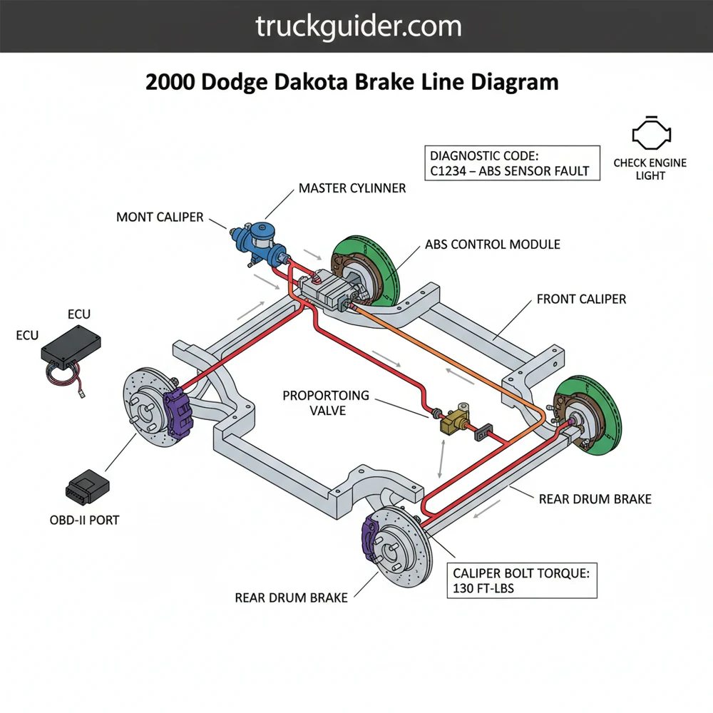
A 2000 Dodge Dakota brake line diagram illustrates the hydraulic path from the master cylinder and ABS module to each individual wheel. It identifies primary and secondary lines, the proportioning valve, and flexible hose connections, allowing you to trace leaks or replace rusted sections to maintain critical braking pressure and vehicle safety.
📌 Key Takeaways
- Identify the specific routing for front and rear hydraulic circuits
- Locate the ABS module and proportioning valve connections
- Ensure all flare fittings meet specific torque spec requirements
- Use the diagram to trace fluid loss or pedal softness issues
- Verify line placement to avoid contact with moving suspension parts
Maintaining the braking system of a mid-size pickup like the 2000 Dodge Dakota is a critical task for any DIY mechanic or truck owner. Over time, the original steel lines are highly susceptible to corrosion, particularly in regions where road salt is frequently used. Navigating the maze of tubes running from the master cylinder to the wheel cylinders and calipers can be daunting without a clear 2000 dodge dakota brake line diagram. This guide is designed to help you identify every component of your hydraulic system, understand the routing along the frame rails, and provide the technical specifications needed to perform a safe and professional repair. By the end of this article, you will have a comprehensive understanding of how to trace, troubleshoot, and replace your brake lines with confidence.
The 2000 Dodge Dakota utilizes two primary braking configurations: Rear-Wheel Anti-lock (RWAL) and 4-Wheel Anti-lock (4WAL). Ensure you identify which system your vehicle has before purchasing replacement lines, as the routing and number of lines coming from the ABS module differ significantly between these two setups.
Understanding the 2000 Dodge Dakota Brake Line Layout
The brake line system on a 2000 Dodge Dakota acts as the circulatory system for hydraulic pressure. It begins at the master cylinder, which is mounted to the brake booster on the driver’s side firewall. From there, two primary lines exit the master cylinder and travel to the combination valve (often referred to as the proportioning valve). This valve is responsible for balancing pressure between the front and rear brakes to prevent premature rear-wheel lockup.
In a standard RWAL configuration, the lines follow a predictable path. Two lines exit the master cylinder and enter the proportioning valve. From the valve, one line runs to the driver’s side front caliper, one runs to the passenger’s side front caliper, and a single long line runs along the driver’s side frame rail toward the rear of the truck. This rear line eventually meets a rubber flex hose located near the rear differential, which then splits into two hard lines that run across the axle to the drum brakes or disc brakes, depending on your specific trim level.
For models equipped with 4WAL, the layout is more complex. The lines from the proportioning valve lead into an ABS hydraulic control unit (HCU). This unit contains solenoids that modulate pressure to each individual wheel. You will notice more lines clustered near the driver-side inner fender well. It is important to note that while the braking system is largely mechanical and hydraulic, the ABS module communicates directly with the vehicle’s ECU (Engine Control Unit). If a leak occurs or pressure drops, the system may trigger a diagnostic code that can be read via the OBD-II port located under the dashboard.
[DIAGRAM_PLACEHOLDER – 2000 Dodge Dakota Brake Line Routing Diagram showing Master Cylinder, ABS Module, Frame Rail Routing, and Rear Axle Split]
Visualizing the split from the proportioning valve to the individual wheels. Note the routing over the fuel tank for the rear line.
Component Identification and Routing Details
📤 Share
💾 Download
When studying the 2000 dodge dakota brake line diagram, you must be able to identify the individual hardware components that keep the system pressurized. The Dakota uses 3/16-inch diameter lines for most of the system, though some fittings may vary in thread size. The most common fitting sizes are 3/8-24, 7/16-24, and 1/2-20 inverted flares. Using a thread pitch gauge is highly recommended if you are flaring your own lines.
- ✓ Master Cylinder: The source of hydraulic pressure, featuring a primary and secondary reservoir.
- ✓ Combination Valve: Located directly below the master cylinder; includes the pressure differential switch that triggers the “Brake” light on the dash.
- ✓ Front Cross-member Line: The line that reaches the passenger front wheel must travel across the front cross-member, often tucked behind the radiator and near the accessory belt path.
- ✓ Rear Main Line: This is the longest line in the truck, running from the engine bay, along the inner driver-side frame rail, and ending at the rear flex hose.
- ✓ Axle Lines: Hard lines mounted directly to the rear axle housing using “tee” blocks and vent bolts.
While the braking system might seem isolated, its physical routing brings it close to other vital engine components. For instance, as you route lines through the engine bay, they must remain clear of the accessory belt to avoid friction damage. Similarly, lines should be kept away from the timing chain cover and exhaust manifolds to prevent the brake fluid from boiling, which would lead to a “spongy” pedal feel. Proper spacing also ensures that the coolant flow through the radiator hoses does not transfer excessive heat to the hydraulic lines.
Step-by-Step Guide to Reading the Diagram and Replacing Lines
📤 Share
💾 Download
If you are using the 2000 dodge dakota brake line diagram to perform a full replacement, following a structured process is essential for safety. Brake work is not an area where you can afford shortcuts.
Brake fluid is highly corrosive to paint and can cause skin irritation. Always wear eye protection and gloves. Ensure the vehicle is securely supported on jack stands—never rely solely on a floor jack while working under the chassis.
Step 1: System Identification
Open the hood and locate the ABS module (if equipped). If you only see a small valve with two lines going in and three coming out, you have RWAL. If you see a large aluminum block with multiple electrical connectors and five or more lines, you have 4WAL. Match this to your diagram.
Step 2: Trace the Leak
Using the diagram as a map, trace the lines from the master cylinder downward. Common failure points on the 2000 Dakota include the section of line running alongside the fuel tank and the area where the front passenger line clips to the cross-member. Look for wet spots or “blooming” rust.
Step 3: Gather Necessary Tools
To work on these lines, you will need flare nut wrenches (10mm, 12mm, 3/8″, 7/16″). Do not use standard open-end wrenches, as they are likely to strip the soft hydraulic fittings. If you are making your own lines, a high-quality double-flaring tool is required. You will also need a torque wrench to ensure every connection meets the required torque spec.
Step 4: Disconnect the Old Lines
Spray all fittings with a high-quality penetrating oil several hours before starting. Disconnect the lines at the proportioning valve first, then work your way toward the wheels. Use a drain pan to catch the old fluid. If a fitting is completely seized, it is often easier to cut the line with a tubing cutter and use a 6-point socket to remove the remaining nut.
Step 5: Bench-Bend the New Lines
Using your old lines as a template, bend the new lines to match the contours shown in the diagram. If you are using NiCopp (Nickel-Copper) tubing, this can be done by hand. If using stainless steel, you will need a specialized tubing bender. Ensure that the lines do not rub against the frame or any moving parts like the steering linkage.
Step 6: Installation and Routing
Thread the fittings into the valves or calipers by hand first to prevent cross-threading. Once finger-tight, use your flare nut wrench to snug them down. Ensure all plastic frame clips are reused or replaced to prevent vibration, which can lead to metal fatigue and future leaks. Check that lines are far enough away from the timing chain area and exhaust components.
Step 7: Bleeding the System
This is the most critical step. Start at the wheel furthest from the master cylinder (Rear Right), then Rear Left, Front Right, and finally Front Left. You must purge all air from the lines until a solid stream of fluid emerges. If you have a 4WAL system, you may need a specialized scan tool to cycle the ABS solenoids to remove trapped air.
When bleeding the brakes, never let the master cylinder reservoir run dry. If air enters the master cylinder, you will have to “bench bleed” it, which requires removing the entire unit from the vehicle and starting over.
Troubleshooting Common Brake Line Issues
Even with a perfect 2000 dodge dakota brake line diagram, you may encounter issues that aren’t immediately visible. One frequent problem is a “soft” or “mushy” brake pedal. If you have confirmed there are no leaks and the system has been bled, the issue could be internal to the ABS hydraulic unit or a failing master cylinder seals.
If your check engine light is on alongside a “Brake” or “ABS” light, the OBD-II system may have stored a specific diagnostic code. While a standard code reader might only show engine-related issues, an advanced scanner can pull “C” (Chassis) codes. For example, a code for a “Pressure Differential Switch” indicates that the proportioning valve has detected an imbalance between the front and rear circuits, usually caused by a burst line or a failed wheel cylinder.
Another common issue is “brake pull,” where the truck yanks to one side when stopping. While this is often a stuck caliper, it can also be a collapsed internal liner in one of the rubber flex hoses. The diagram helps you identify where these flex hoses interface with the hard lines. If the hard line looks good but fluid isn’t reaching the caliper, the flex hose is your primary suspect.
Best Practices and Maintenance Tips
To ensure your new brake lines last as long as the truck itself, consider upgrading the materials. While the factory used coated steel, modern NiCopp (Nickel-Copper) tubing is much easier to work with and is virtually impervious to rust. Stainless steel is another option, though it is much harder to flare and requires a higher torque spec to achieve a proper seal.
Regularly inspect the areas where the lines are near high-heat or high-motion areas. For example, ensure the lines near the engine remain clear of the accessory belt. Heat from the engine can degrade brake fluid over time, so changing your fluid every two years is a best practice. Fresh fluid should be clear or slightly amber; if it looks like coffee, it has absorbed moisture and is corroding your system from the inside out.
Lastly, always respect the torque spec for your specific fittings. Over-tightening a flare nut can crush the flare and cause a leak, while under-tightening can allow air to enter the system under vacuum. Most 3/16″ flare nuts require approximately 10-15 lb-ft of torque. Using a small amount of brake-cleaner to dry the area after installation will help you spot any “weeping” leaks during the initial test drive.
- • Flush brake fluid every 24 months to prevent internal corrosion.
- • Inspect frame-mounted clips for rust or looseness annually.
- • Use NiCopp lines for easier DIY installation and superior rust resistance.
- • Always check for diagnostic codes via the OBD-II port if the ABS light illuminates.
In conclusion, having a 2000 dodge dakota brake line diagram is the first step toward a successful repair. By understanding the routing from the master cylinder to each wheel, identifying your specific ABS configuration, and following the proper safety and installation procedures, you can restore your truck’s stopping power. Whether you are dealing with a sudden failure or performing preventative maintenance, taking the time to do the job right ensures that your Dakota remains a safe and reliable workhorse for years to come.
Frequently Asked Questions
Where is the brake proportioning valve located?
On a Dodge Dakota, the proportioning valve is typically located just below the master cylinder along the driver-side frame rail. It manages fluid pressure between the front disc brakes and rear drum brakes. Following the 2000 Dodge Dakota brake line diagram will help you locate it relative to the ABS unit.
What does the brake line diagram show?
The diagram shows the entire hydraulic network, including the master cylinder, the ABS control module, the hard steel lines running along the frame, and the rubber flex hoses at the wheels. It provides a visual map for correctly routing replacement lines without interfering with the exhaust or suspension systems.
How many connections does the ABS module have?
The ABS module typically features two input lines from the master cylinder and three to four output lines leading to the wheels. The 2000 Dodge Dakota brake line diagram clarifies which port services which wheel, which is essential if you are clearing a specific ABS-related diagnostic code via OBD-II.
What are the symptoms of a bad brake line?
Common symptoms include a spongy brake pedal, visible fluid leaks under the chassis, or a red brake warning light on the dash. In some cases, a significant leak may trigger a check engine light or ABS light if the ECU detects a pressure imbalance or sensor failure during operation.
Can I replace brake lines myself?
Yes, replacing brake lines is a common DIY task, provided you have a flaring tool and flare nut wrenches. However, because it is a critical safety system, you must ensure every fitting is tightened to the correct torque spec and the system is fully bled of air before driving.
What tools do I need for brake line repair?
You will need a set of flare nut (line) wrenches to prevent stripping fittings, a tube cutter, and a double-flaring kit for custom lines. Additionally, an OBD-II scanner can be helpful to cycle the ABS pump via the ECU if air becomes trapped inside the electronic control valves.

![How to Tow a Car with a Truck Long Distance: Step-by-Step Guide [2026]](https://truckguider.com/wp-content/uploads/2026/03/how-to-tow-a-car-with-a-truck-long-dista-featured-1.webp)
![Ram Extended Warranty Price [2026]](https://truckguider.com/wp-content/uploads/2026/03/featured-c324498f.webp)
![Dodge Ram Extended Cab Guide: Quad Cab vs. Crew Cab [2026]](https://truckguider.com/wp-content/uploads/2026/03/dodge-ram-extended-cab-featured-768x403.webp)
![Lifted 3rd Gen Cummins [2026]](https://truckguider.com/wp-content/uploads/2026/03/lifted-3rd-gen-cummins-featured.webp)
![2007 Ram 1500 5.7 Hemi: Specs, Reliability & Common Issues [2026]](https://truckguider.com/wp-content/uploads/2026/03/2007-ram-1500-5-7-hemi-featured.webp)