Dodge Ram 1500 Vacuum Line Diagram: Easy Routing Guide
A 1998 dodge ram 1500 vacuum line diagram illustrates the routing from the intake manifold to the dash controls. It shows connections for the HVAC mode doors, ensuring air flows correctly through the evaporator and heater core while the compressor and blower motor manage cabin temperature and airflow efficiency.
📌 Key Takeaways
- Identify vacuum sources and hose routing for HVAC mode doors.
- The check valve is the most critical component for maintaining vacuum pressure.
- Always check for brittle or cracked lines near the hot engine manifold area.
- Use a hand vacuum pump to test individual actuators for internal leaks.
- Reference this diagram when air defaults only to the defrost vent setting.
Finding the correct 1998 dodge ram 1500 vacuum line diagram is the first step toward reclaiming control over your vehicle’s climate. If you have ever experienced “wild vents”—where the air shifts to the defrost setting every time you accelerate or climb a hill—you are dealing with a failure in the vacuum control system. This article provides a comprehensive breakdown of the HVAC vacuum routing, explaining how the vacuum supply interacts with your compressor, blower motor, and mode doors to maintain cabin comfort. You will learn to identify each vacuum circuit by color, troubleshoot leaks, and restore the functionality of your air handler.
On the 1998 Dodge Ram 1500, the HVAC system uses vacuum pressure to physically move the doors inside the dash. Without steady vacuum, the system defaults to the defrost position as a safety measure to ensure the windshield can always be cleared.
Understanding the HVAC Vacuum Architecture
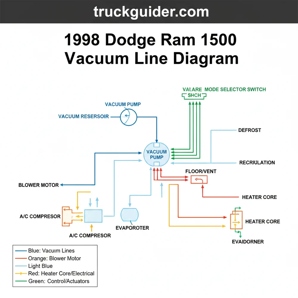
The 1998 Dodge Ram 1500 vacuum line diagram is essentially a map of how engine-generated suction travels from the intake manifold into the passenger compartment. In a gasoline-powered Ram, the vacuum is created by the pistons’ downward stroke. For diesel models, a dedicated mechanical vacuum pump provides this force. This vacuum is stored in a reservoir—often a plastic tank located near the firewall or under the battery tray—to ensure there is enough “reserve” suction when the engine is under heavy load and intake vacuum drops.
The system is divided into two primary sections: the engine bay supply and the interior control circuit. In the engine bay, a main supply line runs from the manifold through a check valve. This check valve is a critical, small plastic component that allows air to flow in only one direction, preventing the vacuum from “bleeding off” back into the engine. From the check valve, the line splits, going to the vacuum reservoir and through the firewall via a rubber grommet.
Once inside the cab, the vacuum line connects to the back of the HVAC control head on the dashboard. This control head acts as a distribution manifold. When you turn the knob from “Vent” to “Floor” or “Defrost,” you are mechanically aligning ports that send vacuum to specific actuators. These actuators are small metal or plastic canisters with internal diaphragms that pull on rods to open or close the doors within the air handler assembly.
(In a visual diagram, you would see a main BLACK line entering the cab, branching into RED, BLUE, YELLOW, and BROWN lines. The RED line typically controls the Recirculation door, the BLUE and YELLOW lines control the Mode doors for vent and floor, and the BROWN line manages the Defrost/Heat mix.)
Component Identification and Role
📤 Share
💾 Download
To fully utilize a 1998 dodge ram 1500 vacuum line diagram, you must understand the relationship between the vacuum system and the mechanical HVAC components. While vacuum moves the doors, other parts are responsible for the temperature and movement of the air.
- ✓ Compressor: This component sits on the engine and pumps refrigerant through the system. It is triggered electrically when the HVAC control head senses that you have selected a mode requiring dehumidification (like A/C or Defrost).
- ✓ Condenser: Located in front of the radiator, the condenser sheds heat from the high-pressure refrigerant.
- ✓ Evaporator: This is the heat exchanger located inside the air handler box under the dash. As air passes over the cold evaporator coils, heat is removed, cooling the cabin.
- ✓ Blower Motor: The electric fan that pushes air through the evaporator and heat exchanger. It does not rely on vacuum for power, but the air it moves is directed by vacuum-operated doors.
- ✓ Heat Exchanger (Heater Core): This component circulates engine coolant to provide warmth. The blend door (often cable or motor-driven on this model) determines how much air passes through this core.
Step-By-Step Guide: How to Read and Apply the Diagram
📤 Share
💾 Download
Interpreting a 1998 dodge ram 1500 vacuum line diagram requires a systematic approach. Follow these steps to trace your system and identify leaks or disconnected lines.
Step 1: Locate the Source
Pop the hood and find the vacuum source on the driver’s side of the intake manifold (on gas engines). Look for a small black plastic tube. Follow it toward the firewall. You should see a small, circular plastic “T” or a check valve. Ensure the connection is tight and the rubber elbows are not dry-rotted.
Step 2: Inspect the Vacuum Reservoir
On many 1998 models, the vacuum reservoir is hidden. It is often a black plastic box or sphere tucked near the passenger side firewall or underneath the battery tray. Tracing the line to this tank is vital; if the tank is cracked or the line is disconnected, the system will lose vacuum whenever you accelerate, causing the vents to flip to defrost.
Step 3: Test the Check Valves
The diagram will show one or two check valves in the engine bay. Remove the check valve and blow into both ends. Air should only pass through in one direction. If air passes both ways or neither way, the valve is faulty and will cause the “wild vent” issue.
Step 4: Trace the Firewall Pass-Through
Look for the main vacuum supply line as it enters the cabin through the firewall. This is usually a thin black nylon line protected by a rubber sleeve. Check for any signs of melting or pinching near the engine block or exhaust manifold.
Step 5: Access the HVAC Control Head
To see where the lines go inside, you may need to remove the trim bezel around the radio and climate controls. Behind the mode selector switch, you will find a multi-colored ribbon of vacuum lines. Refer to your diagram to match colors:
– Black: Main supply (Vacuum in).
– Red: Recirculation door actuator (controls fresh air vs. cabin air).
– Yellow/Blue: Mode door actuators (Vent, Floor, Mix).
– Brown: Defrost actuator.
Step 6: Test Individual Actuators
Using the 1998 dodge ram 1500 vacuum line diagram as a guide, you can use a handheld vacuum pump to test each actuator. Apply 10-15 inches of mercury (Hg) to the line. The actuator should move and, more importantly, hold that pressure. If the needle on your pump drops, the diaphragm inside that specific actuator is leaking.
Do not use excessive force when pulling vacuum lines off the plastic ports of the control head. These plastic nipples become brittle with age and can snap easily, requiring a full replacement of the control unit.
Common Issues & Troubleshooting
The most frequent complaint associated with the 1998 dodge ram 1500 vacuum line diagram is the loss of directional control. Here are the specific signs of failure:
1. Air Only Blows from Defrost: This is the “fail-safe” mode. It indicates a total loss of vacuum to the control head. The most common culprit is a cracked plastic line near the battery or a failed check valve in the engine bay. Since the battery produces acid fumes, the plastic lines nearby often become brittle and disintegrate.
2. Vents Change During Acceleration: This indicates a leak in the vacuum reservoir or a faulty check valve. Under acceleration, the engine produces less vacuum. The reservoir is supposed to maintain the pressure, but if it is compromised, the doors will shift back to the default defrost position until you let off the gas.
3. Hissing Sound Behind the Dash: If you hear a constant hiss while the engine is running, there is a leak at the control head or one of the internal lines. This bypasses the vacuum, reducing the efficiency of the entire system and potentially causing the A/C compressor to cycle incorrectly because the refrigerant pressure isn’t being managed by proper airflow.
If you find a cracked section of the hard plastic vacuum line, you don’t need to replace the whole run. Cut out the damaged section and use a small piece of rubber vacuum hose with the same inner diameter to “splice” the two ends of the plastic line together.
Advanced Maintenance and HVAC Integration
While the 1998 dodge ram 1500 vacuum line diagram focuses on air direction, the health of the entire HVAC system depends on clean components. The air handler box contains the evaporator and the heater core. Over time, dust and debris can clog these heat exchangers, reducing the volume of air the blower motor can push through the system.
In a vehicle of this age, the “return duct” or recirculation intake (located behind the glove box) can often suck in debris or old insulation. If you find that your vacuum system is working perfectly but the airflow is weak, check the intake for obstructions.
Furthermore, ensure that the refrigerant levels are correct. If the compressor is constantly clicking on and off (short-cycling), it may not be a vacuum issue but a low refrigerant charge. However, a vacuum leak can sometimes mimic this by failing to move the mode door to the “A/C” position, preventing the evaporator from receiving the airflow it needs to prevent freezing.
Best Practices for Vacuum System Repair
When performing repairs based on your 1998 dodge ram 1500 vacuum line diagram, quality of materials is paramount.
– Use Silicone Hose: When replacing old rubber elbows or connectors, silicone is superior to standard rubber. It resists heat and ozone much better, meaning it won’t crack in three years like cheap rubber.
– Label Everything: Before disconnecting the multi-port connector on the back of the HVAC head, use small strips of masking tape to label the color of each line. Even though they are “ribboned” together, they can pull apart.
– Secure the Lines: Use small zip ties to secure vacuum lines away from moving parts or high-heat areas like the exhaust manifold. However, do not over-tighten them, as you can crush the thin plastic lines and block the vacuum flow.
– Check the “T” Connectors: Often, the plastic “T” connectors in the engine bay develop hairline cracks that are invisible to the naked eye. If you are struggling to find a leak, replace these inexpensive connectors as a preventive measure.
By following the 1998 dodge ram 1500 vacuum line diagram and understanding how suction moves through your air handler, you can avoid costly mechanic bills. Most vacuum issues on these trucks are caused by simple, external line failures rather than complex internal door failures. With a few feet of vacuum hose, a new check valve, and a bit of patience, you can ensure your Dodge Ram’s HVAC system remains reliable for years to come. Whether you are navigating a summer heatwave or a freezing winter morning, a properly routed vacuum system is the key to maintaining a functional and comfortable cabin environment.
Step-by-Step Guide to Understanding the Dodge Ram 1500 Vacuum Line Diagram: Easy Routing Guide
Identify the vacuum source at the intake manifold to ensure consistent pressure is reaching the system.
Locate the primary check valve near the firewall to check for one-way airflow and physical damage.
Understand how the colored lines correspond to specific HVAC mode door actuators inside the cabin.
Connect a vacuum gauge to verify the system holds pressure without dropping during engine operation.
Verify that switching dash controls changes air flow between vents and floor as intended by design.
Complete the repair by securing loose lines away from high-heat engine components to prevent future melting.
Frequently Asked Questions
Where is the vacuum check valve located?
The vacuum check valve on a Dodge Ram 1500 is typically located near the passenger side firewall or the intake manifold. This small, plastic component prevents vacuum loss during heavy acceleration, ensuring the HVAC doors remain in position while the compressor and condenser regulate the refrigerant flow properly.
What does the HVAC vacuum line diagram show?
This diagram illustrates the complex network of hoses connecting the engine vacuum source to the interior HVAC mode door actuators. It outlines how vacuum pressure moves the doors to direct air through the evaporator or heater core, controlled by the dash switch and powered by the blower motor.
How many vacuum actuators does this system have?
The 1998 Dodge Ram HVAC system generally utilizes four to five vacuum actuators. These actuators respond to vacuum signals from the control head to toggle between defrost, floor, and dash vents. Each connection must be airtight for the system to maintain correct cabin temperature and airflow through the vents.
What are the symptoms of a bad HVAC vacuum line?
Common symptoms include air defaulting to the defrost vents regardless of the setting, or vents changing position only during acceleration. This usually indicates a leak in the lines or a faulty check valve, which disrupts the vacuum needed to counteract the blower motor’s constant air pressure against doors.
Can I replace these vacuum lines myself?
Yes, replacing vacuum lines is a straightforward DIY task using standard rubber or silicone tubing. By following the 1998 dodge ram 1500 vacuum line diagram, you can identify brittle sections and swap them out. Just ensure all connections are tight to prevent any refrigerant cooling efficiency drops.
What tools do I need for vacuum line repair?
You will need a hand-held vacuum pump to test actuators, a pair of needle-nose pliers for removing stuck hoses, and a basic socket set to access the dashboard components. Having a bright flashlight is also essential for inspecting lines tucked behind the condenser or deep under the dash.


![Ram 1500 Off-Road Build Guide: Best Lifts, Tires & Mods [2026]](https://truckguider.com/wp-content/uploads/2026/03/ram-1500-off-road-build-featured.webp)