Reverse Light Wiring Diagram: Easy Setup Guide
A reverse light wiring diagram displays the circuit path from the battery to the reverse switch and backup bulbs. The hot wire carries power through a fuse to the switch, while a traveler wire connects the switch to the lights. Proper grounding via the ground wire completes the circuit, ensuring lights activate when in reverse gear.
📌 Key Takeaways
- Maps the electrical path from the transmission switch to the rear bulbs
- Identifying the reverse light switch on the transmission is essential
- Always disconnect the battery to prevent shorts when working on hot wires
- Use a multimeter to check for continuity across the traveler wire
- Ideal for diagnosing non-functional backup lights or installing a backup camera
Whether you are troubleshooting a failed vehicle inspection or installing a new set of high-intensity auxiliary backup lamps, a clear and accurate reverse light wiring diagram is your most valuable asset. The reverse light circuit is a fundamental safety feature of any vehicle, signaling your intent to move backward to other drivers while illuminating the path behind you. Understanding how the electrical current flows from the power source through the transmission switch and finally to the bulbs ensures you can perform repairs or upgrades with total confidence. In this comprehensive guide, we will break down wire colors, terminal connections, and the proper wiring sequence to get your system back in working order while ensuring all connections meet safety standards.
Most modern automotive reverse light circuits operate on a 12-volt DC system. The circuit is usually protected by a 10-amp or 15-amp fuse located in the interior or engine bay fuse panel. Always consult your specific vehicle’s service manual to confirm the exact fuse location before beginning work.
Decoding the Reverse Light Wiring Diagram
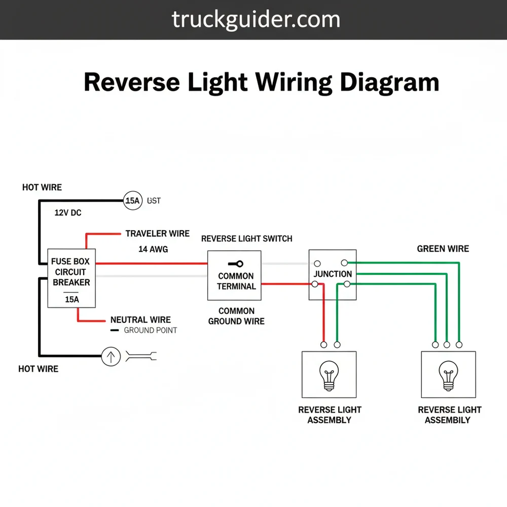
A reverse light wiring diagram serves as a visual map for the electricity’s journey from the battery to the rear of the vehicle. At its core, the diagram represents a series circuit that is interrupted by a switch. When you shift your vehicle into reverse, the mechanical action of the gear selector closes this switch, allowing the “hot wire” to deliver current to the lamps.
In a standard diagram, you will see several distinct components. First is the power source, typically labeled as the battery or a “hot” bus bar in the fuse box. From there, a wire leads to the reverse light switch. In vehicles with automatic transmissions, this switch is often integrated into the neutral safety switch (NSS) located on the transmission housing. In manual vehicles, it is usually a simple two-pin plunger switch.
The diagram will also detail the “common terminal” on the switch, which acts as the entry point for the power. Once the switch is engaged, the electricity exits through the output terminal and travels toward the rear of the car via a long wire often referred to as the load wire or traveler wire in complex relay setups. The color-coding in these diagrams is vital; while many manufacturers use a solid green or white wire for reverse lights, this varies significantly by brand. The diagram will explicitly state these colors so you can identify the correct path among the large harness of wires running along the chassis.
Finally, the diagram illustrates the “ground wire” connection. In automotive applications, the ground is just as important as the power. The light socket must be connected to the vehicle’s metal frame to complete the circuit. If the diagram shows a wire returning to a common ground point, ensure that the connection is clean and free of corrosion.
Anatomy of the Reverse Light Components
📤 Share
💾 Download
To fully grasp the reverse light wiring diagram, one must understand the hardware it represents. Each component has a specific role and physical characteristics that define its placement in the electrical sequence.
The first major component is the fuse. The fuse acts as the sacrificial lamb of the circuit, breaking the connection if the current exceeds a safe level. This prevents the wires from overheating and potentially causing a fire. On the diagram, the fuse is usually the first symbol after the battery.
Next is the switch. As mentioned previously, the reverse light switch is the gatekeeper. On some heavy-duty applications or aftermarket setups, you might encounter switches with a “brass screw” terminal. These are often found on industrial-grade switches where a secure, corrosion-resistant connection is paramount. The “common terminal” on these switches is where the constant 12V power sits, waiting for you to shift into gear.
The wires themselves are categorized by their “gauge.” The gauge refers to the thickness of the wire. For a standard reverse light circuit, 16-gauge or 18-gauge wire is typical. Using a wire that is too thin (a higher gauge number) can lead to a “voltage” drop, resulting in dim lights or even melted insulation. The “voltage” must remain consistent at approximately 12.6V to 14.4V (when the engine is running) to ensure the bulbs reach their full brightness.
Step-by-Step Guide to Implementing the Wiring Diagram
📤 Share
💾 Download
Implementing a reverse light wiring diagram requires a methodical approach. Whether you are replacing a damaged harness or building a circuit from scratch, following these steps will ensure a professional and safe installation.
- ✓ Multimeter or Test Light
- ✓ Wire Strippers and Crimpers
- ✓ Heat Shrink Tubing
- ✓ Correct Gauge Automotive Wire (16 AWG recommended)
- ✓ Electrical Tape or Loom
Step 1: Disconnect the Battery
Before touching any part of the electrical system, disconnect the negative battery terminal. This prevents accidental shorts that could blow fuses or damage sensitive electronic control modules. Safety is the first priority when working with live “hot wire” connections.
Step 2: Locate the Reverse Switch
Find the switch on your transmission. If you are following the diagram for an automatic vehicle, look for the neutral safety switch. Use the diagram to identify which pins are dedicated to the reverse function. There are usually two pins: one for the incoming power and one for the outgoing signal.
Step 3: Route the Hot Wire
From your fuse source, run the primary power wire to the switch. If the switch uses a “brass screw” or terminal block, wrap the wire clockwise around the screw before tightening to ensure a snug fit. This wire is technically the “neutral wire” in some industrial contexts (meaning it carries no current until the switch is flipped), but in automotive terms, it is your switched power.
Step 4: Connect the Traveler Wire
If you are using a relay (recommended for high-powered LED bars), you will run a “traveler wire” from the switch to the relay’s trigger pin (usually pin 86). The relay allows a small amount of current from the switch to control a much larger current directly from the battery to the lights.
Step 5: Identify the Common Terminal
On your relay or switch, identify the “common terminal.” This is the point where the circuit branches or where the primary load enters. Connecting to the correct terminal ensures that the lights only receive power when the vehicle is in reverse and the ignition is in the “ON” position.
Step 6: Run Wires to the Rear
Run the output wire from the switch (or relay) along the vehicle’s frame rail toward the back. Use plastic loom to protect the wire from heat and road debris. Follow the reverse light wiring diagram to ensure you are tapping into the correct side of the bulb socket.
Step 7: Establish a Solid Ground
The “ground wire” is the final piece of the puzzle. Most reverse light sockets have a dedicated ground wire (often black). Connect this wire to a clean, unpainted spot on the vehicle’s chassis. If your lights are dim, a poor ground is the most likely culprit.
Step 8: Test the Voltage
Reconnect the battery. Turn the ignition to the “ON” position (but do not start the engine) and shift into reverse. Use your multimeter to check the “voltage” at the light socket. You should see a reading close to your battery’s standing voltage. If the lights illuminate, you have successfully followed the diagram.
Never replace a blown fuse with one of a higher amperage rating. If a 10A fuse blows, it indicates a short circuit or an overload. Installing a 20A fuse instead can cause the wiring to melt or catch fire before the fuse ever breaks.
Common Issues and Troubleshooting
Even with a perfect reverse light wiring diagram, issues can arise. Understanding how to troubleshoot these problems using your diagram is key to a quick fix.
The most common issue is a complete failure of both lights. If both lights are out, the problem is likely at the beginning of the circuit. Start at the fuse. If the fuse is intact, use your diagram to locate the reverse switch and test for power at the “hot wire” entering the switch. If you have power going in but no power coming out when in reverse, the switch itself has failed.
If only one light is working, the “reverse light wiring diagram” shows that the circuit usually splits at the rear of the vehicle. This means the problem is downstream from the split—likely a burnt-out bulb, a corroded socket, or a broken “ground wire” on that specific side.
Use dielectric grease in your bulb sockets and on your ground connections. This specialized grease prevents moisture from reaching the metal terminals, stopping corrosion before it starts and ensuring your lights stay bright for years.
Another frequent problem is flickering lights. This is almost always caused by a loose “common terminal” connection or a frayed “traveler wire” that is intermittently touching the chassis and causing a partial short. Use your diagram to trace the physical path of the wire and look for areas where the insulation might have rubbed through against the frame.
Tips and Best Practices for Wiring Success
When working with your reverse light wiring diagram, there are several professional strategies you can use to ensure the longevity of your work.
First, always use the correct “gauge” of wire. While 18-gauge is standard for single bulbs, if you are adding multiple auxiliary lights, you should step up to 14-gauge or 12-gauge wire to handle the increased current. High-power lights draw more amperage, and thin wires will create resistance, which generates heat and reduces “voltage” at the light source.
Second, pay close attention to your “brass screw” connections and terminal crimps. A common mistake for beginners is failing to crimp terminals tightly enough. A loose crimp creates high resistance, which can melt the plastic connector. Use a high-quality ratcheting crimp tool for the best results.
Third, consider the environment. Automotive wiring is exposed to salt, water, and extreme temperature swings. Always use marine-grade heat shrink tubing over your splices. This tubing has an internal adhesive that melts when heated, creating a waterproof seal around the wire connection.
Lastly, keep your wiring organized. Use zip ties to secure the “hot wire” and “ground wire” away from moving parts like the driveshaft or suspension components. A clean installation is not just about aesthetics; it is about preventing mechanical damage to the electrical system.
Voltage and Resistance Specifications
For those who want to be truly precise, monitoring the “voltage” and resistance (ohms) of the circuit provides the ultimate diagnostic data. A healthy reverse light circuit should show very little resistance between the switch and the bulb.
Using the ohms setting on your multimeter, you can check the continuity of the traveler wire. A reading of 0.2 to 0.5 ohms is ideal. If you see a reading of 10 ohms or higher, the wire is likely damaged or heavily corroded internally, even if the insulation looks fine. This “invisible” damage is a common cause of dim lights that many DIYers overlook.
Furthermore, ensure that your “neutral wire” or return path is not restricted. In DC systems, the ground completes the circuit. If the ground has a high resistance, the “voltage” will drop significantly across the load (the bulb), leading to poor performance. Always clean the metal surface with a wire brush before securing your ground terminal.
Summary and Final Checklist
In conclusion, mastering the reverse light wiring diagram is a matter of understanding the path of the current and the role of each component. By identifying the hot wire, ensuring a solid ground, and using the correct gauge for your needs, you can maintain a safe and reliable vehicle.
Before you close your hood and call the job finished, run through this final checklist:
1. Is the fuse the correct amperage for the circuit?
2. Are all “brass screw” or terminal connections tight and shielded?
3. Does the “voltage” at the bulb match the battery voltage?
4. Is the “ground wire” secured to bare metal?
5. Have you protected the “traveler wire” from heat sources and moving parts?
By following these guidelines and referencing your reverse light wiring diagram, you ensure that your vehicle remains safe, visible, and compliant with road regulations. Whether you are performing a simple repair or a complex auxiliary lighting installation, the principles of proper wiring sequence and terminal identification remain the same. Clear communication between your gear selector and your rear lamps is vital for every mile you drive.
Frequently Asked Questions
Where is the reverse light switch located?
The reverse light switch is typically located on the transmission housing. For manual vehicles, it is screwed into the side; for automatics, it is often integrated into the neutral safety switch. Refer to your vehicle’s service manual to find the exact mounting point relative to the shift linkage.
What does a reverse light wiring diagram show?
A reverse light wiring diagram shows the electrical flow required to illuminate backup lights. It details the connection between the power source, fuse box, reverse gear switch, and the bulbs. This visual aid helps technicians identify where power is interrupted or where a short circuit might be occurring.
How many wires does the reverse light circuit have?
Most systems use three main connections: a hot wire from the fuse, a traveler wire leading to the lamps, and a ground wire at the bulb socket. In some advanced setups, a common terminal on a relay might be used to handle higher current loads for upgraded LED lighting.
What are the symptoms of a bad reverse light circuit?
Symptoms of a failing circuit include lights that stay on constantly, lights that don’t turn on at all, or flickering when shifting. If the fuse is intact but the bulbs are dark, the problem is likely a faulty reverse switch or a break in the neutral wire.
Can I repair the reverse light wiring myself?
Replacing a reverse light switch or repairing a wire is generally a beginner-to-intermediate DIY task. Most switches are easily accessible under the vehicle or hood. However, tracing complex wiring through the chassis requires patience and a basic understanding of automotive electrical systems to ensure safe operation.
What tools do I need for reverse light troubleshooting?
To work on this system, you will need a digital multimeter for testing voltage and continuity. Basic hand tools like a socket set or wrenches are required to remove the switch. Additionally, wire strippers, crimpers, and electrical tape are necessary if you need to repair damaged sections.


![Ram Extended Warranty Price [2026]](https://truckguider.com/wp-content/uploads/2026/03/featured-c324498f.webp)

![Dodge Durango Bolt Pattern Guide: Specs & Fitment Guide [2026]](https://truckguider.com/wp-content/uploads/2026/03/dodge-durango-bolt-pattern-featured.webp)