dodge ram 1500 wiring diagram free: A Professional Guide to Locating and Interpreting Electrical Schematics
For any Dodge Ram 1500 owner, the complexity of the vehicle’s electrical system can be the difference between a simple fix and an expensive trip to the dealership. Electrical malfunctions are responsible for a significant portion of truck downtime, yet finding a reliable, high-quality dodge ram 1500 wiring diagram free of charge remains a challenge for many DIY enthusiasts. Modern trucks are no longer just mechanical beasts; they are rolling computers connected by miles of copper and complex data protocols. This comprehensive guide provides professional insight into sourcing trusted schematics, interpreting technical symbols, and utilizing these diagrams to perform expert-level troubleshooting on your Ram’s electrical grid, ensuring your repairs are both safe and effective.
The Fundamental Role of a Dodge Ram 1500 Wiring Diagram Free Resource
In the realm of automotive repair, a wiring diagram serves as the “GPS” for your truck’s nervous system. It is a complete visual representation of every connection, component, and terminal within the vehicle’s architecture. Unlike a simple block diagram—which merely shows that two components are related—a true electrical schematic provides the precision of wire paths, specific terminal locations within connectors, and critical ground points. Without this guide, attempting to trace a faulty sensor or a flickering headlight becomes an exercise in frustration and potential damage.
Research indicates that approximately 70% of modern vehicle repairs involve electrical systems, according to data from the Automotive Service Association. This statistic highlights why having an accurate complete schematic is no longer optional for the serious owner. Whether you are dealing with the Totally Integrated Power Module (TIPM) on a fourth-generation Ram or the advanced Uconnect infotainment system in a newer DT model, the diagram allows you to see how power flows and where it might be interrupted.
Evolution of the Ram Electrical Grid
The jump in complexity over the last two decades is staggering. For example, a 1998 Dodge Ram 1500 headlight circuit is relatively straightforward: a switch, a relay, a fuse, and the bulbs. In contrast, a 2020+ Ram 1500 utilizes a CAN bus (Controller Area Network) integrated LED lighting system. In the modern truck, when you pull the headlight switch, you aren’t sending power to the lights; you are sending a digital request to a computer module, which then decides whether to ground the circuit and illuminate the LEDs. A quality wiring diagram is the only tool that can bridge the gap between these two vastly different eras of engineering.
By The Numbers
Repairs Involving Electrical Systems
Avg. Hourly Diagnostic Cost
Annual Cost for Pro Software

Sourcing Reliable Dodge Ram 1500 Wiring Diagrams: Free vs. Paid Options
When searching for a “dodge ram 1500 wiring diagram free,” many owners fall into the trap of downloading unverified PDF files from obscure forums. These files are often incomplete, missing specific pages for high-end trim levels like the Laramie or Limited, or—worse—applicable to the wrong model year. To ensure you are using reliable data, you must evaluate your sources carefully. Legitimate free resources do exist, such as the AutoZone Repair Help section or local public library databases. Many libraries provide free access to expert tips via ChiltonLibrary or EBSCO, which host factory-style schematics accessible with a standard library card.
Professional technicians often pay over $1,500 annually for software like ALLDATA to ensure diagram accuracy. For a DIYer, this is overkill, but it underscores the value of verified information. If you choose to use a free resource, always cross-reference the wire color codes on the diagram with the physical harness in your vehicle before making any cuts or connections. You can also consult the official guide from Mopar for specific parts-related wiring info. Incorrect wiring can damage expensive electrical components and potentially cause a vehicle fire, making accuracy your number one priority.
✅ Pros of Official Diagrams
- Includes technical service bulletins (TSBs)
- Precise terminal and pin-out data
- Specific to your VIN and trim level
- Covers complex CAN-Bus data paths
❌ Cons of Free Forum Downloads
- Often missing key circuit pages
- May apply to wrong engine/trim
- Potential malware in PDF links
- Low-resolution, unreadable text

Decoding Automotive Electrical Symbols and Technical Terminology
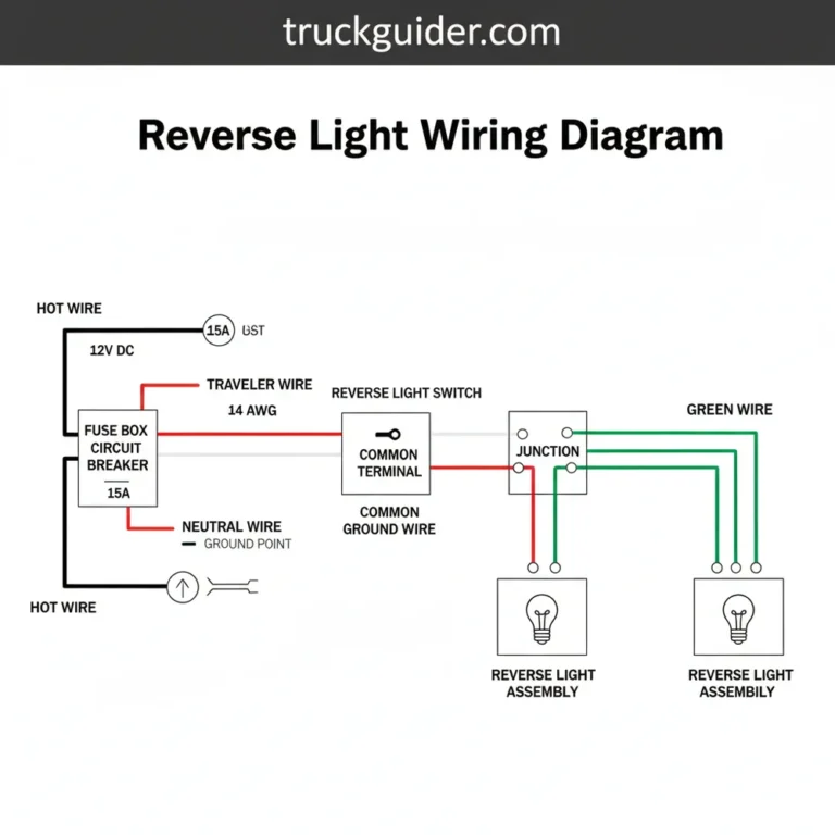
Once you have secured a quality schematic, the next hurdle is interpreting it. Dodge factory service manuals utilize standardized ISO and SAE symbols. A basic understanding of these is essential for any expert repair. For example, a zig-zag line represents a resistor, while a line with a small “loop” or “break” indicates a fuse or circuit breaker. Most importantly, you must master the Mopar wire color coding system.
In a Ram 1500 diagram, wires are often labeled with a two-part abbreviation. For instance, WT/OR represents a White wire with an Orange tracer (stripe). Understanding this prevents you from probing the wrong circuit in a harness containing dozens of similar-looking wires. Additionally, you need to identify physical locations based on alphanumeric codes:
- G-Codes: G105 refers to a specific ground point, usually a bolt on the frame or engine block.
- C-Codes: C202 identifies a specific multi-pin connector.
- Splices: Represented by a solid dot where multiple wires meet inside the harness wrap.
Take a standard 5-pin Bosch-style relay, frequently used for fog lights or fuel pumps in Ram trucks. The diagram will show pins 85 and 86 as the trigger circuit (the coil), pin 30 as the fused power source, and pin 87 as the output to the component. Without the diagram, you wouldn’t know if the relay is “normally open” or “normally closed,” which is a nuanced but vital distinction for proper function.
When reading pin-out diagrams for connectors, pay attention to whether you are looking at the “face” of the connector or the “wire side.” Plugging your multimeter probe into the wrong side of the pin can result in false readings or damaged terminals.
Step-by-Step Electrical Troubleshooting Using Your Wiring Diagram
The average cost of professional electrical diagnosis ranges from $75 to $150 per hour. By following a professional methodology, you can save significant money while ensuring a permanent fix. Before you start, always disconnect the battery to prevent accidental shorts—especially when working near the airbag (SRS) system or the PCM.
📋
Professional Troubleshooting Workflow
Use the wiring diagram to identify all fuses and fusible links related to the malfunctioning component. A visual check isn’t enough; use a multimeter to check for continuity across the fuse.
This is the gold standard for pros. Use the schematic to find the power source and the load. Measure voltage across the circuit while it’s under load to find high resistance caused by corrosion or frayed wires.
If you find a short, use the junction points and connectors shown in the diagram to disconnect sections of the harness. This allows you to narrow down exactly which segment of wire is grounded.
Consider a common scenario: a Ram 1500 owner experiences a parasitic battery drain. By using a trusted wiring diagram, they can identify every circuit that remains “hot” when the ignition is off. By pulling fuses while monitoring the drain with a Digital Multimeter (DMM), they might trace the issue back to a faulty glove box light switch or a hanging relay in the TIPM that isn’t visible without the schematic’s pathing info.
Common Electrical Failure Points in Dodge Ram 1500 Models
Every vehicle has its “Achilles heel,” and for the Ram 1500, several well-documented electrical issues often require a wiring diagram to solve. One of the most prominent is the Totally Integrated Power Module (TIPM) found in 2006-2012 models. The TIPM is a fuse box with internal circuit boards and relays. When an internal relay fails—such as the fuel pump relay—the entire module often needs replacement. However, with a comprehensive wiring diagram, some owners perform a “TIPM bypass,” jumping external power to the fuel pump circuit to save thousands in repair costs.
Never probe a CAN-Bus communication wire (usually twisted pairs) with a standard test light. The high current draw of the bulb can fry the sensitive logic circuits in the truck’s computers. Always use a high-impedance multimeter for data circuit testing.
Corrosion and Grounding Issues
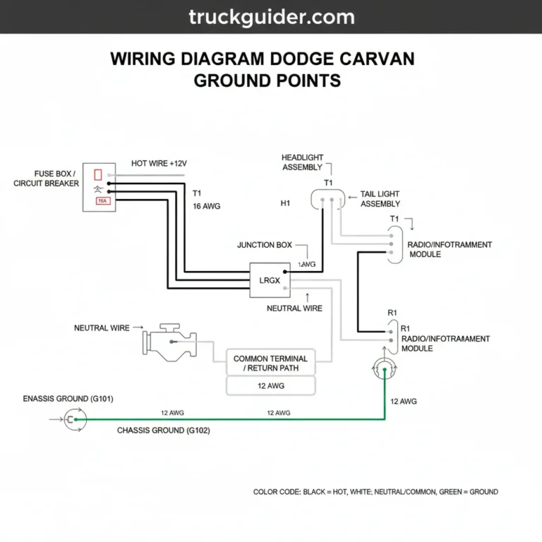
Another common failure point is the trailer towing harness and 7-way plug. Because these are exposed to the elements, corrosion often travels up the wires into the main harness. A reliable diagram is essential here to ensure you are matching the correct pin functions during a replacement. Furthermore, grounding strap degradation is a major cause of “ghost” electrical issues, where multiple unrelated systems fail at once. A professional technician uses the diagram to locate the three primary ground paths—Engine, Body, and Frame—to ensure they are clean and tight. You can find more Ram specs regarding common ground locations on enthusiast forums, which often host crowdsourced data on these failure points.
Wiring diagrams are essential professional tools for diagnosing the 70% of repairs involving electrical components. While free resources exist through libraries and authorized retailers, verifying the diagram’s accuracy against your specific model year and trim is critical for safety. Mastering symbols and color codes allows for precise troubleshooting of common issues like TIPM failures or ground faults. Before beginning your next electrical repair, download a verified schematic and invest in a quality multimeter to ensure a safe and successful fix. Your Ram’s reliability depends on the integrity of its electrical grid; treat it with the expert care it deserves.
Frequently Asked Questions
Where can I find a free wiring diagram for my specific Dodge Ram 1500 year?
The most reliable sources for a free dodge ram 1500 wiring diagram include the AutoZone ‘Repair Help’ section, which offers free schematics for registered users, and local public library portals like ChiltonLibrary. Be cautious of forum PDFs, as they may lack the specific technical service bulletins or trim-level variations necessary for a professional-grade repair.
How do I read a professional-grade wiring diagram?
Reading a wiring diagram requires understanding standard ISO symbols for components like relays and ground points. Start by identifying the power source (usually at the top) and follow the wire path through fuses and switches down to the load (the component) and finally to the ground. Note the color codes, such as ‘RD/YL’ for a red wire with a yellow stripe.
What tools do I need to troubleshoot electrical problems in my truck?
A professional troubleshooting kit must include a high-impedance Digital Multimeter (DMM) to measure voltage, resistance, and continuity without damaging the truck’s ECU. Additionally, a 12V test light is useful for quick power checks, and a set of back-probe pins allows you to test connectors without piercing the wire insulation, which prevents future corrosion.
What do the different symbols in a wiring diagram mean?
Symbols represent physical electrical components: a jagged line typically denotes a resistor, a coil represents a relay or solenoid, and a triangle pointing to a line indicates a ground. Circles with letters inside often refer to connectors (C) or splices (S). Consult the legend page of a factory service manual to ensure you are interpreting Ram-specific symbols correctly.
Are wiring diagrams the same for all trim levels of the Dodge Ram 1500?
No, wiring diagrams vary significantly between trim levels. For example, a Ram 1500 Tradesman has a much simpler wiring architecture than a Limited or Laramie trim, which includes complex circuits for heated seats, air suspension, and advanced infotainment. Always ensure your diagram matches your specific VIN or trim level to avoid incorrect pin-out interpretations.


![Battery Saver Mode Dodge Journey Warning [2026]](https://truckguider.com/wp-content/uploads/2026/03/featured-5a4205d1-768x768.webp)