How to Reset the Electronic Stability Control Light (DIY Steps) 2026
The modern automotive landscape has been irrevocably transformed by the advent of active safety systems. Among these, Electronic Stability Control (ESC) stands as the single most significant development in vehicle dynamics since the introduction of the pneumatic tire. For owners and operators of light-duty and heavy-duty trucks, understanding ESC is not merely an academic exercise; it is a functional necessity for safe towing, off-road navigation, and daily operation.
This report provides an exhaustive analysis of ESC systems, specifically tailored to the truck market (Ford F-Series, Chevrolet Silverado/GMC Sierra, Ram 1500/2500/3500, and Toyota Tundra/Tacoma), detailing the technical architecture, failure modes, diagnostic procedures, and the critical “Service ESC” warning light that serves as the system’s primary communication interface.
The Evolution from Passive to Active Safety
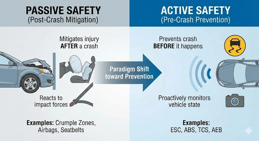
Historically, vehicle safety focused on passive measures—systems designed to mitigate injury after a crash has occurred, such as crumple zones, seatbelts, and airbags. However, the late 20th and early 21st centuries saw a paradigm shift toward active safety—systems designed to prevent the crash from happening in the first place. ESC is the pinnacle of this active safety evolution. It is a computerized technology that improves a vehicle’s stability by detecting and reducing loss of traction (skidding).
While Anti-lock Braking Systems (ABS) manage longitudinal tire slip during braking and Traction Control Systems (TCS) manage longitudinal slip during acceleration, ESC is unique in its ability to manage lateral dynamics. It continuously monitors the driver’s intended path against the vehicle’s actual path. When a discrepancy arises—indicating a loss of control—the system intervenes by applying brakes to individual wheels and modulating engine torque to restore the vehicle to the desired trajectory.
Statistical Efficacy and Safety Impact
The implementation of ESC has yielded profound improvements in road safety, particularly for vehicles with higher centers of gravity, such as pickup trucks and SUVs. Research conducted by the National Highway Traffic Safety Administration (NHTSA) and the Insurance Institute for Highway Safety (IIHS) provides compelling data on ESC’s effectiveness:
- Rollover Reduction: ESC reduces the risk of fatal single-vehicle rollovers by 75% for SUVs and 72% for passenger cars. This statistic is critical for truck owners, as the geometry of a pickup truck inherently predisposes it to rollover events during high-speed evasive maneuvers.
- Run-Off-Road Mitigation: Fatal run-off-road crashes were reduced by 70% for light trucks and vans (LTVs), compared to a 36% reduction for passenger cars. This disparity highlights that while ESC is beneficial for all vehicles, it is indispensable for trucks.
- Overall Fatality Reduction: NHTSA estimates that ESC reduces fatal single-vehicle crashes of SUVs by 56% and passenger cars by 38%.
ESC Light On?
Don’t ignore the warning. Electronic Stability Control reduces single-vehicle crash risks by up to 67%.
What is Electronic Stability Control?
ESC is your car’s digital safety net. It continuously monitors steering input against actual vehicle direction. If it detects a loss of traction or “plowing” (understeer), it instantly applies brakes to individual wheels to restore control.
Why It Matters
Without ESC, a sudden swerve can lead to a spin-out. With ESC, the computer corrects the slide faster than any human driver can react.
Vehicle Dynamics Comparison
Comparing vehicle stability metrics in adverse conditions.
Why is My ESC Light On?
The light indicates the system has disabled itself due to a fault. It is rarely the ESC controller itself; usually, it is a sensor feeding data to the system that has failed.
Top 5 Common Failures
Wheel Speed Sensor
The #1 culprit. Exposed to road grime, brake dust, and heat. If the car can’t read wheel speed, ESC cannot function.
Steering Angle Sensor
Located in the steering column. Tells the computer where you *want* to go. misalignment after wheel alignment is common.
Brake Light Switch
A cheap part ($20) that often fails. If the computer doesn’t know you are braking, it disables traction systems.
Estimated Repair Costs
Cost varies significantly by vehicle make and model. While sensors are relatively affordable, labor for electrical diagnosis can add up quickly.
Pro Tip:
Always scan for “C-Codes” (Chassis Codes) before buying parts. Don’t fire the parts cannon!
DIY Troubleshooting Workflow
1. Visual Inspection
Check tires for damage & verify brake fluid levels.
2. Scan OBD-II Codes
Look for ‘C’ codes (e.g., C1234) indicating chassis faults.
3. Check Battery Voltage
Low voltage causes random sensor dropouts. Ensure >12.4V.
4. Inspect Wiring
Look for frayed wires near wheel wells (speed sensors).
The Real World Impact
Data from the National Highway Traffic Safety Administration (NHTSA) confirms that ESC is one of the most significant safety advancements since the seatbelt.
- Single-Vehicle Crashes: Drastically reduced by preventing overcorrection.
- Rollover Accidents: Specifically effective in high-center-of-gravity vehicles like SUVs and Trucks.
© 2026 TruckGuider Infographics
The Sensor Suite and Control Logic
To comprehend the meaning of an illuminated Electronic Stability Control light, one must first understand the complex network of components it represents. The ESC system is not a standalone unit but a high-level software function that commands the hardware of the ABS and Traction Control systems, guided by a dedicated array of inertial and driver-input sensors.
The Sensory Nervous System
The ESC Control Unit (ECU) relies on a continuous stream of data—sampled hundreds of times per second—to model the vehicle's physical state. The core sensor suite includes:
Steering Angle Sensor (SAS)
The SAS is the primary input for determining driver intent. Located within the steering column (often behind the clock spring), this sensor measures the position of the steering wheel in degrees and the rate of change (how fast the wheel is being turned).
- Technology: Modern SAS units typically utilize Anisotropic Magnetoresistive (AMR) elements or optical encoders to provide a precise, digital signal of the steering angle.
- Role in Logic: This data tells the ECU where the driver wants the vehicle to go. If the SAS reports a 45-degree left turn, but the vehicle is moving straight, the system identifies an understeer condition.
Yaw Rate Sensor
This is the heart of the stability system. The yaw rate sensor measures the vehicle's rotational velocity around its vertical axis (the Z-axis). In simpler terms, it measures how fast the nose of the truck is turning left or right.
- Location: To function correctly, this sensor must be placed as close to the vehicle's center of gravity as possible. In many trucks, it is mounted under the center console, beneath the driver's seat, or integrated into the Airbag Control Module.
- Mechanism: It typically employs micromachined tuning forks or vibrating gyroscopic elements. Coriolis forces acting on these vibrating elements during rotation cause a voltage change proportional to the yaw rate.
- Role in Logic: This data tells the ECU where the vehicle is actually going.
Lateral Acceleration Sensor (Accelerometer)
Often integrated into the same housing as the yaw rate sensor (creating a "cluster" sensor), the lateral accelerometer measures the centrifugal force acting on the vehicle during cornering.
- Role in Logic: It quantifies the grip level. If the vehicle is generating high lateral G-forces, the tires are gripping. If the yaw rate is high but lateral G is low, the vehicle is likely spinning on a low-friction surface (ice or gravel).
Wheel Speed Sensors (WSS)

Mounted at each wheel hub, these sensors monitor the rotational speed of each tire.
- Active vs. Passive: Older trucks used passive (inductive) sensors that generated an AC voltage signal that increased with speed. Modern trucks (2010+) largely use Active (Hall Effect or Magnetoresistive) sensors. Active sensors receive a 12V power supply and return a digital square wave signal, allowing them to read accurate speeds even at near-zero velocity—a requirement for advanced features like Hill Descent Control and intricate traction management.
- Role in Logic: These sensors detect wheel lockup (for ABS), wheel spin (for TCS), and differential wheel speeds that indicate cornering.
The Physics of Intervention: Understeer vs. Oversteer
The ESC ECU continuously compares the "Desired Yaw Rate" (calculated from Steering Angle and Vehicle Speed) with the "Actual Yaw Rate" (measured by the Yaw Sensor). When the difference exceeds a pre-programmed threshold, the system intervenes.
Mitigating Understeer (Plowing)
Scenario: A truck enters a slippery corner too fast. The driver turns the wheel left, but the momentum carries the truck straight forward.
- Physics: The front tires have lost traction and are sliding.
- ESC Intervention: The system applies the brake to the Inner Rear Wheel (e.g., left rear).
- Result: This braking force creates a drag on the inside corner of the vehicle, generating a yaw moment that pulls the nose of the truck into the turn, realigning it with the driver's steering input.
Mitigating Oversteer (Fishtailing)

Scenario: A driver makes a sudden lane change to avoid an obstacle. The rear of the truck swings out, threatening to spin the vehicle around.
- Physics: The rear tires have lost traction, and the vehicle is rotating faster than intended.
- ESC Intervention: The system applies the brake to the Outer Front Wheel (e.g., right front).
- Result: This braking force on the outside front corner creates a counter-moment that opposes the spin, "snapping" the rear end back into line.
Torque Management
In both scenarios, the ESC system will almost simultaneously command the Engine Control Module (ECM) to reduce torque. This is achieved by:
- Retarding ignition timing.
- Cutting fuel injection pulses.
- Closing the electronic throttle plate. Reducing power is critical because applying torque to tires that are already sliding will only reduce their ability to generate lateral grip (according to the friction circle concept in tire physics).
The Human-Machine Interface
The "Electronic Stability Control Light" is a standardized ISO symbol, typically depicting a car with wavy skid marks behind it inside a yellow triangle. However, the behavior of this light conveys different messages, and manufacturer-specific text warnings can add layers of complexity.
Flashing vs. Steady Illumination
The most fundamental diagnostic distinction for a driver is whether the light is flashing or steady.
- Flashing Light: Active Protection
- Meaning: If the light flashes rapidly while driving, the system is working. It has detected a loss of traction or stability and is actively applying brakes or cutting power.
- Context: You might feel the truck shudder, hear a grinding noise (the ABS pump activating), or feel the engine power cut out momentarily.
- Driver Action: This is a warning that you are driving near the limit of adhesion. The correct response is to ease off the accelerator and steer smoothly. Do not panic brake, as the system is already managing brake pressure.
- Steady Light: System Disabled
- Meaning: If the light remains illuminated constantly, the system has detected a fault or has been manually deactivated.
- Implication: When the light is solid, the ESC system is OFF. The vehicle will rely solely on mechanical grip. ABS may or may not still be functional depending on the nature of the fault.
- Driver Action: Check if the "ESC Off" switch was accidentally pressed. If not, the vehicle requires service. While generally safe to drive carefully, the vehicle is vulnerable to spinning out in emergency maneuvers.
Manufacturer-Specific Nomenclature and Warnings
Truck manufacturers market their stability systems under different names, leading to confusion when researching warning lights.
Table 1: ESC Nomenclature and Dashboard Messages by Manufacturer
| Manufacturer | System Name | Acronyms | Common Warning Messages |
| General Motors (Chevy/GMC) | StabiliTrak | STS, TC | "Service StabiliTrak", "Service Traction Control", "Engine Power Reduced" |
| Ford Motor Co. (F-Series) | AdvanceTrac with RSC | RSC, ESC | "Service AdvanceTrac", "Trailer Sway Reduce Speed", "Hill Descent Control Fault" |
| Stellantis (Ram/Jeep) | Electronic Stability Program | ESP, BAS | "Service Electronic Stability Control", "Service Shifter" (Rotary Dial Models) |
| Toyota (Tundra/Tacoma) | Vehicle Stability Control | VSC, VDIM | "Check VSC System", VSC OFF light, TRAC OFF light |
| Nissan (Titan/Frontier) | Vehicle Dynamic Control | VDC | "VDC OFF", "SLIP" light |
The "Christmas Tree" Effect: Correlated Warning Lights

The ESC system is deeply integrated with other vehicle modules. Consequently, an ESC warning light is rarely seen alone.
- ESC + Check Engine Light: This is a frequent occurrence, especially in GM and Toyota trucks. Because ESC relies on torque management (cutting engine power) to stabilize the vehicle, a fault in the engine (like a misfire, P0300) means the engine cannot reliably control torque. Therefore, the ECU disables ESC as a safety precaution.
- Insight: In this scenario, the root cause is engine-related, not brake-related. Fixing the spark plug or ignition coil (misfire) will clear both lights.
- ESC + ABS Light: This combination points to a failure in the shared hardware of the chassis. The most common culprit is a Wheel Speed Sensor, as both ABS and ESC require wheel speed data to function. If the ABS module itself fails, both lights (and often the red 'BRAKE' light) will illuminate.
- ESC + Trailer Brake Light: On trucks equipped with integrated trailer brake controllers, a fault in the ESC system will often disable the trailer brake controller, as the systems share data regarding vehicle deceleration and sway.
Truck-Specific Implementations and Common Failure Points
Pickup trucks present unique dynamics challenges: a light rear end (when empty), high center of gravity, and heavy towing duties. Consequently, manufacturers have developed specialized iterations of ESC.
Ford AdvanceTrac with Roll Stability Control (RSC)
Ford's system, standard on the F-150 and Super Duty, is distinct because it includes a second gyroscopic sensor specifically to monitor the roll rate (tipping) of the vehicle. Standard ESC infers roll risk from lateral Gs; RSC measures it directly.
- Common Failure: The steering angle sensor inside the steering column is a known weak point. Additionally, wiring harness corrosion near the spare tire (where the fuel pump driver module and rear sensor wiring converge) can cause communication loss.
- "Service AdvanceTrac" Root Causes: Often linked to a wheel speed sensor, but also frequently caused by a steering rack failure in models with Electronic Power Assist Steering (EPAS). If the rack cannot communicate strictly with the AdvanceTrac module, the light illuminates.
GM StabiliTrak (Silverado/Sierra)
GM's StabiliTrak is notorious for its sensitivity to engine performance.
- The AFM/DOD Connection: GM trucks with Active Fuel Management (cylinder deactivation) are prone to lifter failures and spark plug fouling. Even a minor misfire that the driver can barely feel will trigger the "Service StabiliTrak" message immediately.
- Throttle Body Issues: The Throttle Position Sensor (TPS) is critical for StabiliTrak's torque management. Carbon buildup on the throttle body butterfly valve can cause TPS correlation errors, triggering the StabiliTrak light and "Reduced Engine Power" mode.
- Ground Straps: The G218 ground on the dashboard and the chassis ground straps on the frame rails of GMT900 and K2XX platform trucks are prone to corrosion, causing intermittent StabiliTrak faults.
Ram Electronic Stability Program (ESP)
Ram trucks (formerly Dodge) utilize a system heavily influenced by Mercedes-Benz architecture (from the DaimlerChrysler era).
- Brake Light Switch: The brake pedal switch in Ram trucks is a dual-signal switch. One signal lights up the tail lights; the other tells the ESP computer that braking is requested. If these signals disagree due to a faulty switch, the ESP light illuminates. This is a cheap and common fix.
- TIPM Issues: The Totally Integrated Power Module (fuse box) in older Rams is known for internal relay failures that can cut power to the ABS/ESP module, causing intermittent warning lights.
Trailer Sway Control (TSC)
For the truck owner, ESC is not just about keeping the truck on the road; it is about keeping the trailer there too. Trailer Sway Control (TSC) is a functional extension of the ESC software standard on almost all modern trucks.
Mechanics of Trailer Sway
Trailer sway (or snaking) acts as a harmonic oscillator. Once it begins, it can amplify due to driver over-correction or aerodynamic forces. The ESC system's yaw sensor can distinguish the rhythmic lateral forces of a swaying trailer from a standard slide.
- Detection: The system detects a yaw rate that oscillates (left-right-left) at a specific frequency characteristic of a trailer instability.
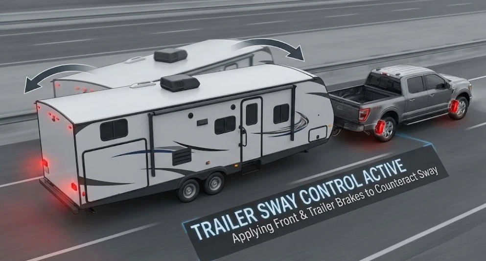
- Intervention: Unlike standard ESC which might brake one wheel, TSC often brakes both front wheels or uses asymmetric braking to counteract the sway's phase. Crucially, it aggressively cuts engine throttle to reduce speed, which is the primary energy source for the sway.
- Trailer Braking: On trucks with integrated 7-pin trailer connectors and OEM brake controllers, the TSC system can send a signal to the trailer's electric brakes to engage. This "stretches" the combination, pulling the trailer straight—a maneuver that is much more effective than braking the truck alone.
Warning Indicators
When TSC activates, the ESC light will typically flash rapidly, and the Driver Information Center (DIC) will display "TRAILER SWAY REDUCE SPEED". This is a critical warning that the setup (tongue weight, speed, or wind conditions) is unstable.
Compatibility with Weight Distribution Hitches
A common question is whether Weight Distribution (WD) hitches interfere with ESC.
- Answer: No. In fact, they complement each other. A WD hitch restores weight to the truck's front axle, ensuring the front tires have enough traction for the ESC system's steering and braking interventions to be effective. Without a WD hitch, a heavy tongue weight lifts the front steering tires, rendering the ESC's ability to correct understeer almost useless.
Off-Road Protocols: ESC Management in 4x4 Environments
While ESC is a safety net on pavement, it can be a liability in off-road environments. Understanding how to manage ESC modes is essential for effective 4x4 operation.
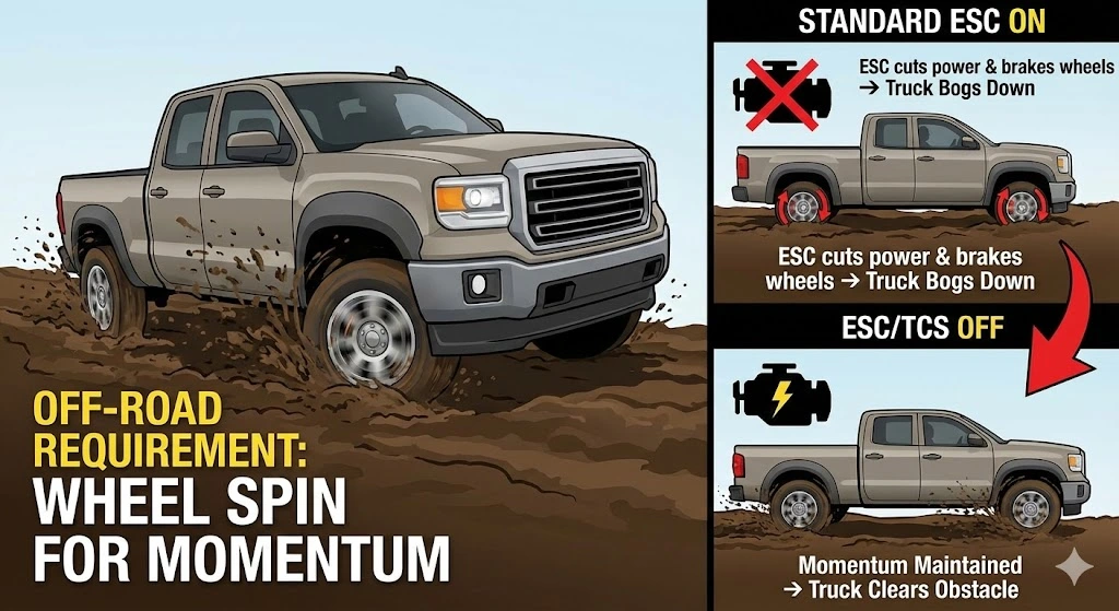
The Momentum Problem
In deep substrates like mud, sand, or snow, tires must spin to maintain momentum and clear their tread blocks.
- The Conflict: Standard ESC and TCS interpret wheel spin as a loss of traction. The system will cut throttle and brake the spinning wheels. In deep mud, this throttle cut can cause the truck to bog down and become stuck instantly.
- The Solution: Deactivation.
Hierarchy of Deactivation
Most trucks offer a multi-stage deactivation logic via the dashboard button :
- Stage 1: Traction Control Off (Single Press)
- Function: Disables engine torque reduction for wheel spin. Allows tires to spin freely.
- Status: "TCS OFF" light illuminates.
- Use Case: Getting out of a snowy driveway, powering through a mud hole, or driving in deep sand. ESC (lateral stability) remains active to prevent spin-outs.
- Stage 2: Full ESC Off (Press and Hold for 5-10 Seconds)
- Function: Disables both Traction Control and Electronic Stability Control.
- Status: "ESC OFF" and "TCS OFF" lights illuminate.
- Use Case: High-speed desert running, drifting (track use), or extreme technical off-roading where sliding the vehicle is necessary to maneuver.
- Note: Many systems will automatically re-engage if speeds exceed ~35 MPH for safety.
- 4WD Low Range Integration
- Function: Shifting a truck into 4-Low almost universally disables ESC automatically.
- Reasoning: The massive torque multiplication in low range would confuse the TCS algorithms. Furthermore, off-road driving in low range typically involves speeds below the threshold where ESC is effective or necessary.
- Hill Descent Control: While ESC is off in 4-Low, the ABS pump remains active to provide Hill Descent Control, which pulses brakes to manage downhill speed without driver input.
Comprehensive Diagnostic Guide
When the "Service ESC" light illuminates steadily, a systematic diagnostic approach is required.
Diagnostic Flowchart
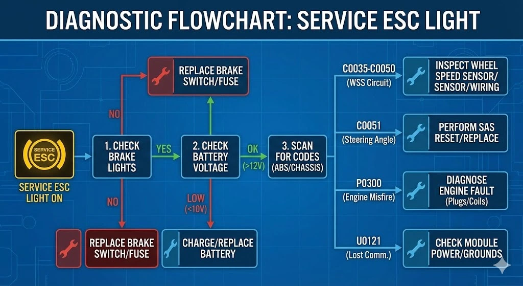
- Check Brake Lights: Are the tail lights working? If not, check the brake pedal switch and fuses.
- Check Battery: Load test the battery. A voltage drop below 10V during cranking can cause module communication errors.
- Scan for Codes: Connect a scanner capable of reading ABS/Chassis (C-codes). A basic engine reader is insufficient.
- Interpret Codes:
- C0035-C0050: Wheel Speed Sensor Circuit faults.
- C0051: Steering Angle Sensor.
- P0300-P0308: Engine Misfire (Primary cause on GM/Toyota).
- U0121: Lost Communication with ABS Module.
- Live Data Analysis: View the data stream while driving.
- Wheel Speed: Do all four sensors read the same speed in a straight line?
- Steering Angle: Does the sensor read 0 degrees when the wheel is centered?
- Yaw Rate: Does the sensor read 0 deg/sec when stopped?
Component Testing Procedures
Testing Wheel Speed Sensors (Multimeter Method)
- Resistance Test (Passive Sensors): Disconnect the sensor. Set multimeter to Ohms (Ω). Measure resistance across the two pins. Compare to factory spec (typically 1000Ω - 2500Ω). Open circuit (OL) or 0Ω indicates a failed sensor.
- Voltage Test (Passive Sensors): Set multimeter to AC Volts. Spin the wheel by hand. You should see voltage generation (e.g., >100mV AC). No voltage means a bad sensor or too large an air gap due to rust.
- Active Sensors: Cannot be reliably tested with resistance. They require a 12V power source and an oscilloscope to see the square wave signal. Diagnostics usually involve swapping the sensor to the other side of the vehicle to see if the code follows the sensor.
Steering Angle Sensor Reset (Lock-to-Lock)
After a dead battery or alignment, the SAS may need recalibration.
- Procedure:
- Start Engine.
- Turn steering wheel fully to the Left lock. Hold for 2 seconds.
- Turn steering wheel fully to the Right lock. Hold for 2 seconds.
- Center the wheel.
- Turn off ignition, then restart. This procedure teaches the ECU the mechanical limits and center point of the steering rack.
Repair Cost Analysis: Parts and Labor
Repair costs vary significantly based on vehicle design (e.g., hub-integrated sensors vs. bolt-on sensors).
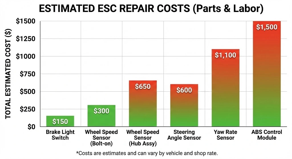
Table 2: Estimated Repair Costs (Full-Size Trucks)
| Component | Part Cost (OEM) | Labor Time | Total Estimated Cost | Notes |
| Wheel Speed Sensor (Bolt-on) | $40 - $100 | 0.5 - 1.0 hrs | $150 - $300 | Common on Ford F-150 rear axles. |
| Wheel Speed Sensor (Hub Assy) | $150 - $350 | 1.5 - 2.5 hrs | $350 - $650 | Chevy Silverado Front/Ram Front. Requires replacing full wheel bearing. |
| Brake Light Switch | $20 - $50 | 0.5 hrs | $80 - $150 | Common DIY fix for Ram trucks. |
| Steering Angle Sensor | $150 - $300 | 1.5 - 2.5 hrs | $400 - $600 | Often requires airbag removal. |
| Yaw Rate Sensor | $500 - $800 | 1.0 - 2.0 hrs | $800 - $1,100 | Located under center console/seats. |
| ABS Control Module | $600 - $1,000 | 2.0 - 4.0 hrs | $1,000 - $1,500 | Requires programming and brake bleeding. |
The "Hub Assembly" Cost Factor
Truck owners should be aware that on many modern heavy-duty trucks (Silverado 2500HD, Ram 2500), the front wheel speed sensors are permanently integrated into the sealed wheel bearing hub assembly. If the $40 sensor fails, the entire $300 hub unit must be replaced. This design increases repair costs significantly but protects the sensor from the elements.
Regulatory Landscape and Safety Standards
The legal framework surrounding ESC reinforces its importance.
Federal Motor Vehicle Safety Standards (FMVSS)
- FMVSS No. 126: Mandated that all passenger vehicles and light trucks (GVWR < 10,000 lbs) manufactured after September 1, 2011, must be equipped with ESC. This is why you will see ESC lights on every modern F-150 or Silverado.
- FMVSS No. 136: Extended this mandate to heavy-duty truck tractors and large buses (GVWR > 26,000 lbs). It required compliance for 3-axle tractors by August 1, 2017, and all other tractors by August 1, 2019. This regulation was driven by the need to reduce jackknifing and rollover accidents in the commercial trucking sector.
State Inspection Implications
Can you pass a state inspection with the ESC light on?
- Safety Inspections: In states with rigorous safety inspections (e.g., Virginia, New York, Pennsylvania, Massachusetts), a lit ESC or ABS light is often an automatic FAIL. The logic is that the vehicle's critical safety systems are compromised.
- Emissions Testing: The ESC light itself will not cause an emissions failure unless it is triggered by a "Check Engine" light (P-code). If the ESC light is on due to a chassis fault (C-code), it does not affect the OBD-II emissions readiness monitors.
Conclusion
The Electronic Stability Control light is a guardian, a mechanic, and a warning flare all in one. For the truck owner, it signifies a sophisticated system working to counteract the laws of physics that threaten high-center-of-gravity vehicles. From the gyroscopic yaw sensors detecting a trailer sway event to the precise braking interventions preventing a rollover on an icy highway, ESC is indispensable.
While the illumination of the "Service ESC" light can be a source of frustration—and potentially a significant repair bill—it serves a vital function. It alerts the driver that the safety net is withdrawn. Whether caused by a simple brake switch failure in a Ram, a corroded ground strap in a Silverado, or a steering rack fault in an F-150, addressing these warnings is not just about clearing a dashboard light; it is about restoring the vehicle's capacity to protect its occupants in the split-second moments when control is lost. Understanding the system's physics, its interaction with towing and off-road modes, and its diagnostic pathways empowers owners to make informed decisions, ensuring their trucks remain as safe and capable as designed.

![2012 Ram 2500 Leveling Kit Guide: Best Fits & Tire Sizes [2026]](https://truckguider.com/wp-content/uploads/2026/03/2012-ram-2500-leveling-kit-featured-768x403.webp)

![2002 Dodge Ram 1500 Interior Configuration, Material [2026]](https://truckguider.com/wp-content/uploads/2026/03/featured-1d381560-768x768.webp)
![Ram 1500 Single Cab Short Bed Performance, Specifications, [2026]](https://truckguider.com/wp-content/uploads/2026/03/featured-7450283a.webp)