Service Trailer Brake System: The Ultimate Troubleshooting Guides 2026
The modern automotive landscape has witnessed a paradigm shift in towing technology, moving from passive, reactive systems to active, integrated control networks. At the heart of this evolution lies the Integrated Trailer Brake Controller (ITBC), a complex system that interfaces directly with a towing vehicle’s hydraulic braking, anti-lock braking system (ABS), and stability control modules.
While this integration offers unprecedented safety and control, it also introduces a sophisticated layer of potential failure points that manifest in the ubiquitous and dreaded dashboard warning: “Service Trailer Brake System.”
This report serves as an exhaustive technical dossier on the subject. It is designed for automotive technicians, fleet managers, and advanced enthusiasts who require a granular understanding of the system’s architecture, failure logic, and repair protocols. The analysis focuses primarily on the two market leaders in heavy-duty towing—General Motors (Chevrolet/GMC) and Ram Trucks—while establishing universal principles applicable to all SAE J2863 standard towing interfaces.
The Shift from Aftermarket to OEM Integration
Historically, trailer braking was achieved through aftermarket controllers mounted under the dashboard, utilizing a simple pendulum or time-delay circuit to send voltage to the trailer. These standalone units were robust but isolated; they had no data regarding the truck’s wheel speed, hydraulic pressure, or stability status. The advent of the ITBC (Integrated Trailer Brake Controller) changed this dynamic fundamentally.
By embedding the controller into the vehicle’s Controller Area Network (CAN), OEMs enabled “proportional braking” that scales trailer stopping power based on the driver’s exact master cylinder pressure.
However, this digitization means that a simple resistive variance—caused by a corroded pin or a loose ground—is no longer just a “bad connection”; it is a system-wide fault. The Body Control Module (BCM) monitors the circuit continuity thousands of times per second. If the parameters fall outside the rigid software lookup tables, the system disables output to the trailer to protect the module, triggering the “Service Trailer Brake System” alert. This default-to-safety logic, while protective of the hardware, can leave a driver with 10,000 pounds of un-braked cargo, creating a critical safety hazard.
The Anatomy of the Warning
The “Service Trailer Brake System” message is a generic catch-all for a multitude of specific errors. It does not identify the component at fault; rather, it indicates that the system has detected a condition that prevents safe operation. This could range from a $40 dashboard switch failure to a corroded frame ground, a blown fuse, or a compromised 7-way connector. Understanding the context of the warning—whether it appears continuously, intermittently over bumps, or only when braking—is the first step in a complex diagnostic chain.
The implications of this warning extend beyond mechanical inconvenience. Federal regulations, specifically 49 CFR § 393.43, mandate operational service brakes on all towed trailers engaged in interstate commerce. Operating a combination vehicle with a known brake system fault constitutes a violation of these safety standards and exposes the operator to significant liability in the event of a collision. Furthermore, the loss of ITBC function often disables concomitant safety features such as Trailer Sway Control, which relies on the ability to independently brake the trailer wheels to dampen harmonic oscillation.
Service Trailer Brake System
The dreaded dashboard warning. It disables your trailer brakes and signals a break in the electrical continuity. Don’t replace the module until you read this.
Where to Look First
Most truck owners panic and assume the truck’s computer (ITBC Module) is dead. However, real-world mechanics data suggests the problem is almost always “downstream”—at the bumper or on the trailer itself. This chart breaks down the most frequent causes of the “Service Trailer Brake System” message.
Key Takeaway
Over 70% of issues originate at the 7-way connector (corrosion/loose fit) or within the trailer’s own wiring. The expensive ITBC module is rarely the culprit.
Source: Aggregated Mechanic Forum Data & Service Bulletins
Integrated vs. Aftermarket
Understanding which system you have helps in diagnosis. Modern trucks use Integrated Trailer Brake Controllers (ITBC) which speak directly to the ECU, making them smarter but more sensitive to electrical faults.
Factory ITBC
💻- ✓ Fully integrated into the dashboard information center.
- ✓ Uses hydraulic brake pressure data for proportional braking.
- ⚠ Extremely sensitive to resistance changes (corrosion triggers codes easily).
Aftermarket Unit
🔌- ✓ Usually mounted under the dash (knee knocker).
- ✓ Often uses inertia sensors (pendulums) rather than ECU data.
- ✓ More forgiving of minor wiring resistance issues.
The Physics of Failure
The “Service Trailer Brake System” message is often triggered by Bad Grounds. When a ground connection corrodes, resistance increases. This chart demonstrates how corrosion impacts the voltage reaching your trailer brakes.
Diagnostic Tip:
If your brake output voltage drops significantly below 12V at the plug, check the white ground wire on the truck side frame rail.
The Diagnostic Logic Tree
Follow this path before buying any parts.
Step 1: Isolate the Variable
Disconnect the trailer. Does the message persist?
Truck Side Issue
- Check Fuse box (ITBC fuses)
- Check 7-Way plug back-side for corrosion
- Inspect frame ground wire
Trailer Side Issue
- Clean Trailer Plug contacts
- Check magnet wires for fraying
- Test brake electromagnets (Ohms)
Advanced Check: The Dummy Load
Use a “Trailer Emulator” or 12V test light to simulate a trailer load. This tricks the truck into thinking a trailer is connected for safe voltage testing.
© 2024 TruckGuider.com – All Rights Reserved.
Theoretical Framework: Physics and Engineering of Electric Trailer Brakes
To diagnose the “Service Trailer Brake System” fault effectively, one must first master the underlying physics of the load being controlled. The ITBC does not merely “send electricity” to the trailer; it manages a dynamic electromagnetic circuit.
Electromagnets and Friction Material
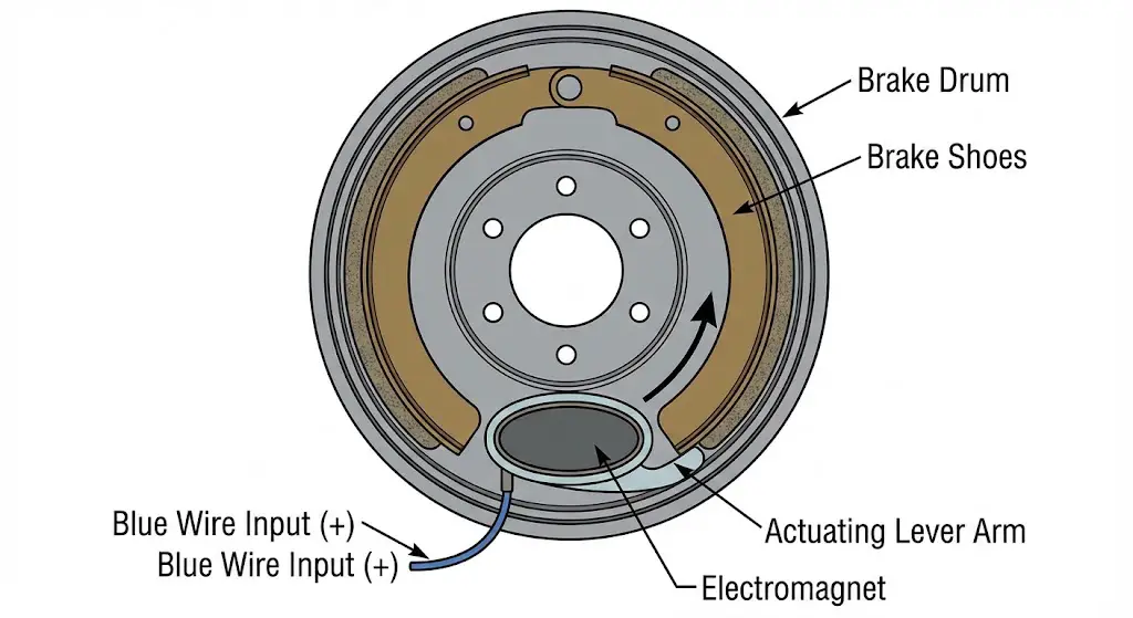
Electric trailer brakes operate on the principle of electromagnetism. Inside the trailer’s brake drum, an electromagnet is suspended on an actuating arm. When the ITBC sends current (amperage) down the blue wire, the magnet energizes and is attracted to the spinning vertical face of the brake drum. As the magnet grabs the drum, the rotational force (torque) drags the actuating arm, which in turn expands the brake shoes against the drum surface.
The “Service Trailer Brake System” fault is often triggered by the ITBC’s monitoring of this specific circuit’s resistance. A standard 7-inch brake magnet typically has a resistance of 3.2 to 4.0 ohms. If the ITBC detects resistance significantly lower than this (indicating a short to ground) or significantly higher (indicating a broken wire or corrosion), it sets a Diagnostic Trouble Code (DTC) such as C1114. The system is designed to protect the output transistors in the control module from overheating due to a short circuit.
Pulse Width Modulation (PWM) and Signal Monitoring
Unlike simple DC circuits that are either “on” or “off,” modern ITBC systems utilize Pulse Width Modulation (PWM). The controller rapidly switches the 12V output on and off to control the average voltage reaching the magnets. This allows for smooth, proportional braking.
- The Check Pulse: Even when the brakes are not applied, the ITBC sends a very short voltage pulse down the brake line every few seconds. This pulse is too short to activate the magnets but long enough to measure the circuit’s integrity.
- The Phantom Fault: This “check pulse” is the reason why the “Service Trailer Brake System” or “Check Trailer Wiring” message can appear even when the driver is not touching the brake pedal. The system constantly “pings” the trailer to verify presence. If moisture or corrosion in the 7-way connector alters the resistance during this ping, the system flags a fault immediately.
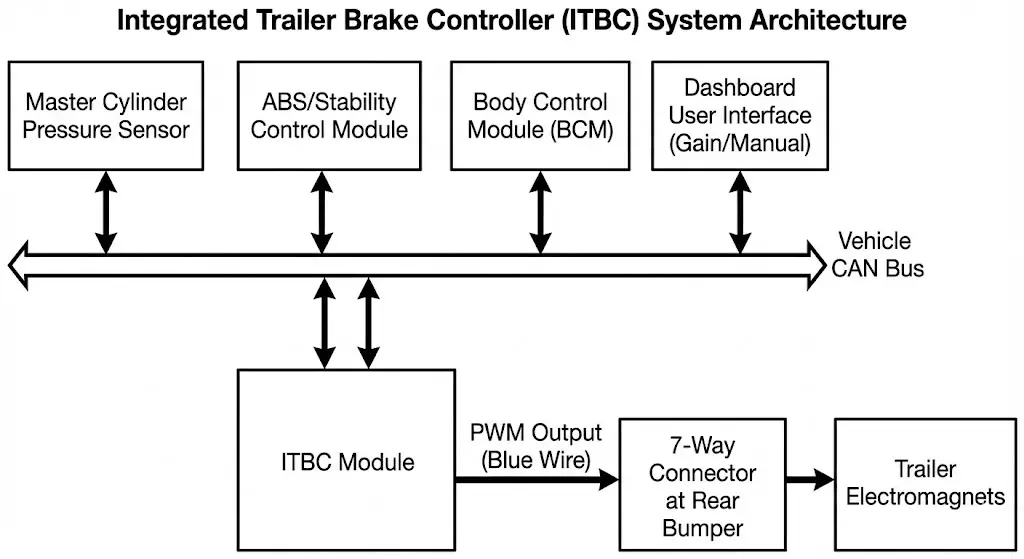
The Role of the Integrated Controller
The ITBC acts as the central processor for towing operations. It receives inputs from:
- Master Cylinder Pressure Sensor: Determines how hard the driver is braking.
- Vehicle Speed Sensors: Determines the rate of deceleration.
- Stability Control Module: Detects yaw (sway) or traction loss.
- User Interface: The gain setting and manual override slider.
Deep Dive: General Motors Architecture (Silverado & Sierra)
General Motors’ implementation of the ITBC, particularly across the GMT900 (2007-2013), K2XX (2014-2018), and T1XX (2019-Present) platforms, exhibits specific, documented failure modes. The fleet data suggests that while the modules themselves are robust, the peripheral wiring and user interfaces are prone to degradation.
The Dashboard Switch Failure (K2XX Platform)
On the 2014-2018 Silverado and Sierra 1500/2500/3500 models, the most statistically significant cause of the “Service Trailer Brake System” warning—when no trailer is connected—is the dashboard control switch itself.
- Component ID: The switch assembly (Part # 23145874, updated to 84108373) is located to the left of the steering wheel.
- Mechanism of Failure: The switch utilizes internal contacts to register the position of the manual squeeze tabs and the gain adjustment buttons. Over time, these contacts suffer from oxidation or mechanical wear, leading to “signal jitter.” The BCM detects this fluctuating signal as an implausible input (e.g., the switch signaling “brake apply” and “no brake” simultaneously) and declares the switch defective.
- Symptoms: The warning message cycles rapidly or appears randomly while driving on smooth roads. The gain setting may change spontaneously.
- Diagnostic Validation: If the warning can be triggered or cleared by wiggling the switch or adjusting the gain, the switch is almost certainly the culprit.
- Repair Protocol: Replacement is a Level 1 repair. It requires removing the fuse panel cover and the lower knee bolster (secured by 7mm screws). The switch pops out from the rear. No reprogramming is required for the switch itself, making this a viable DIY repair for owners.
The “Stud 1 / Stud 2” Power Supply Issue (GMT900)
For the earlier generation of trucks (2007-2013), a design peculiarity in the Under-Hood Electrical Center (UBEC) often confuses owners and technicians alike. The power feeds for the trailer system were not fully connected at the factory.
- The Disconnect: Two heavy-gauge wires (Red/Black) are typically taped to the harness bundle between the fuse box and the driver’s side fender. These wires correspond to “Stud 1” (12V Auxiliary Power to the 7-way) and “Stud 2” (Power to the Trailer Brake Controller).
- The Symptom: A newly installed brake controller (factory or aftermarket) powers on but displays “Service Trailer Brake System” or fails to output voltage because the high-current supply line is disconnected.
- The Fix: Technicians must physically locate these ring terminals, route them to the threaded studs on the front of the fuse box, and secure them with M8/M6 nuts. This is often overlooked during Pre-Delivery Inspections (PDI) or used vehicle reconditioning.
The Achilles Heel: Ground G401
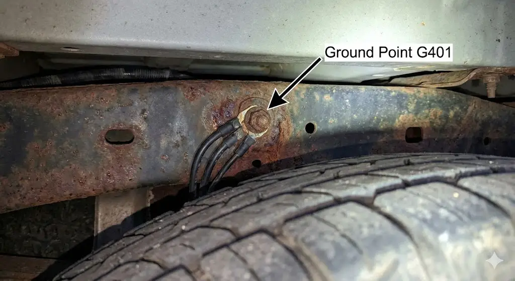
Grounding is the single most critical aspect of the GM electrical architecture, and Ground Point G401 is the nexus of trailer brake failures.
- Location: G401 is located on the rear frame rail, typically on the driver’s side, often obscured by the spare tire or the rear crossmember.
- The Corrosion Cell: The interaction between the steel frame, the copper wire terminal, and the zinc-coated bolt creates a galvanic cell. Accelerated by road salt and moisture (brine), this connection corrodes, increasing resistance.
- Impact on ITBC: The trailer brake circuit is a high-amperage load (up to 12-16 amps). According to Ohm’s Law ($V = I \times R$), even a small amount of resistance at the ground point causes a significant voltage drop when the current spikes. The ITBC detects this voltage drop as a system fault and disables the output.
- Remediation: The only permanent fix is mechanical abrasion. The bolt must be removed, the frame rail sanded to bare bright metal, the terminal cleaned, and the assembly re-torqued. The application of conductive grease (or fluid film) after assembly is crucial to prevent recurrence.
Module Failure and Programming
The Trailer Brake Control Module (TBCM) on GMT900 trucks is located on the rear frame rail, exposing it to extreme environmental stress. Water intrusion into the module housing can cause the circuit board to swell and short.
- DTC C1114: This code, “Trailer Brake Solenoid Control Circuit,” is the hallmark of ITBC issues. While it often points to wiring, it can indicate internal module failure if the wiring tests good.
- Replacement Complexity: Unlike the switch, replacing the TBCM is not plug-and-play. The new module must be “flashed” or programmed with the vehicle’s VIN and calibration software using a J2534 pass-through device and a GM SPS2 subscription. Installing a module from a junkyard or Amazon without programming will result in a non-functional system.
Ram Trucks Architecture (Gen 4 & Gen 5)
Ram Trucks (formerly Dodge Ram) utilize a different architecture centered around the Totally Integrated Power Module (TIPM) in older models and a Central Gateway in newer models. The “Service Trailer Brake System” warning in Rams has a distinct set of triggers.
The “Trailer Disconnected” Phantom Cycle
A specific and maddening issue plagues Ram owners: the dashboard message cycling between “Trailer Connected” and “Trailer Disconnected” repeatedly while driving.
- The Sensitivity Issue: Ram’s ITBM (Integrated Trailer Brake Module) uses a sensing pin in the 7-way connector to detect trailer presence. The firmware threshold for continuity is extremely tight. Even a micro-second loss of contact due to road vibration causes the system to flag a disconnect.
- The Mechanical Fix: This is rarely a software fault. It is a mechanical mismatch between the truck’s 7-way socket and the trailer’s plug. The internal spring clips of the truck’s socket fatigue over time. The “Fork Trick”—using a small screwdriver to slightly spread the male pins on the trailer plug—improves contact pressure and often resolves the issue.
- OEM Part Quality: Ram uses Pollak-brand sockets. It is widely documented that replacing the factory socket with a fresh Pollak 11-893 unit solves the issue when cleaning does not.
Integrated Trailer Brake Module (ITBM) and Fuse F11
The power distribution for the Ram ITBM is handled through the Power Distribution Center (PDC) under the hood.
- Fuse F11: This 30-amp J-case fuse supplies the main power to the brake controller. A blown F11 fuse immediately triggers the “Service Trailer Brake System” message because the module cannot self-test.
- Fuse F87: This 10-amp fuse supplies the logic/ignition power.
- TIPM Failure: On 2010-2014 Ram trucks, the TIPM itself is a known failure point. Internal relays that manage the trailer circuits can fail, necessitating a TIPM replacement or an external bypass relay wiring job.
2018+ Security Gateway Module (SGW) and Diagnostics
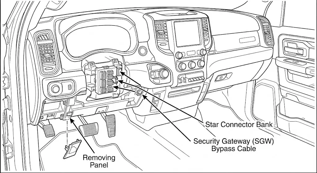
For the 2018 model year and newer, Ram introduced a Security Gateway Module (SGW) to protect the vehicle’s CAN bus from cyber intrusions. This has significant implications for DIY diagnostics.
- The Firewall: The SGW blocks unauthorized write commands to the vehicle networks. This means a standard OBDII scanner can read codes but cannot clear them or perform active tests on the brake controller.
- The Bypass Solution: To diagnose the ITBM deeply, technicians must install an “SGW Bypass Cable.” This physical adapter connects to the Star Connector (usually located behind the radio or near the driver’s kick panel), bypassing the security module to allow full bidirectional communication.
- AlphaOBD: This software has become the gold standard for Ram enthusiasts. With a bypass cable and an OBDII Bluetooth dongle, AlphaOBD allows owners to:
- Enable the factory trailer brake controller sales code (XHC) without visiting a dealer.
- Change the ITBM configuration settings.
- Reset the module logic if it becomes corrupted.
- Procedure: The user must access the “Body Control Module” menu, select “Car Configuration Change,” and update the “Trailer Brake” settings to “Present.” This “tells” the truck that the controller is installed, activating the dashboard displays.
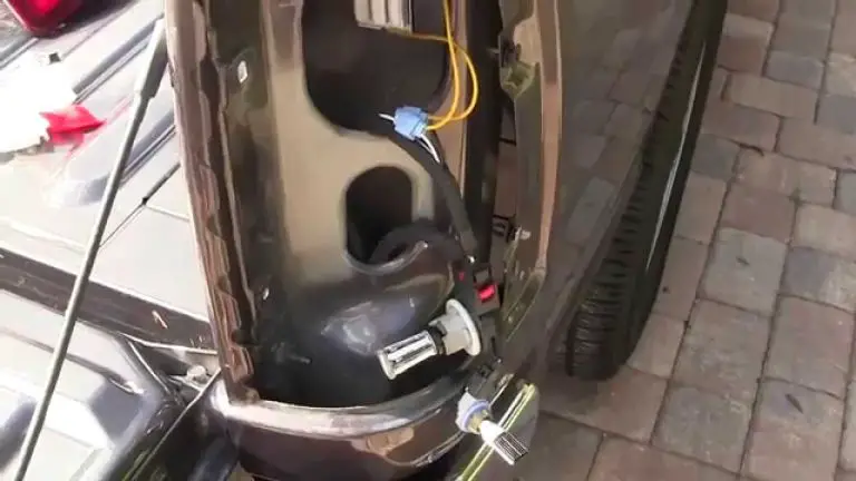
The 7-Way Connector: The Nexus of Environmental Failure
Regardless of the vehicle make, the 7-way trailer connector (SAE J2863) is the single most common point of failure. Situated at the rear bumper, it exists in a harsh environment of road spray, salt brine, and physical abuse.
Galvanic Corrosion and “Green Death”
The interface between the brass or copper pins of the connector and the wire harness is prone to oxidation.
- The Mechanism: When moisture enters the connector housing, it bridges the gap between the 12V constant power pin (Pin 4, Black) and the Ground pin (Pin 1, White). This electrolysis creates copper oxide (green corrosion) and rapidly eats away the wire terminals.
- TSB 21-NA-155: General Motors issued this bulletin to address the high rate of “Check Trailer Wiring” messages. The bulletin explicitly blames low-quality aftermarket trailer plugs that do not meet SAE dimensional tolerances. It recommends switching to Pollak Heavy Duty plugs to ensure a tight seal and proper pin engagement.
The Dielectric Grease Controversy
A common debate in automotive circles involves the use of dielectric grease.
- The Science: Dielectric grease is insulating (non-conductive). Its primary function is to seal rubber gaskets and prevent moisture intrusion.
- The Risk: If a technician fills the female sockets of the 7-way connector with dielectric grease, they can hydraulically prevent the male pins from seating fully. Furthermore, if the contact pressure is weak, the grease acts as an insulator, preventing the electrical connection entirely.
- Best Practice:
- Clean pins with electrical contact cleaner and a mechanical brush.
- Tighten the pin tension manually.
- Apply a thin film of dielectric grease to the housing seal and the base of the pins, but do not pack the socket.
- For corroded pins, specialized conductive grease (carbon-infused) is a better option, though replacement is preferred.
Diagnostic Pinout Reference
To properly diagnose the “Service Trailer Brake System,” one must verify the truck’s output at the 7-way plug.
| Pin No. | Function | Color (SAE Standard) | Diagnostic Value (Key On) |
| 1 | Ground | White | 0 Ohms to Frame |
| 2 | Trailer Brakes | Blue | Variable Voltage (with Gain) |
| 3 | Tail/Running Lights | Green (or Brown) | 12V (Lights On) |
| 4 | 12V Battery Charge | Black | 12V Constant |
| 5 | Left Turn/Stop | Yellow | Pulsing 12V |
| 6 | Right Turn/Stop | Red (or Green) | Pulsing 12V |
| 7 | Reverse Lights | Purple | 12V (in Reverse) |
Comprehensive Diagnostic Methodology
When faced with the “Service Trailer Brake System” warning, a shotgun approach of replacing parts is expensive and often ineffective. The following diagnostic tree isolates the variable.
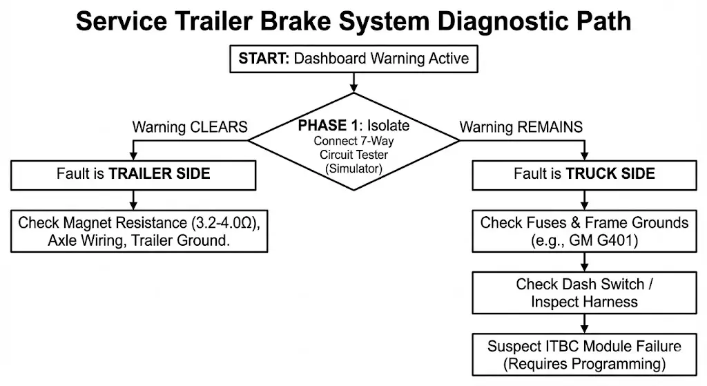
Phase 1: Isolation (The “Dummy” Test)
The first step is to determine if the fault lies with the Truck or the Trailer.
- Disconnect the Trailer: If the message persists on the dashboard with the trailer unplugged, the fault is 100% within the truck (Switch, Module, Fuse, or Wiring).
- The Circuit Tester: Plug in a dedicated 7-way circuit tester (e.g., Tekonsha 6562). This tool simulates a trailer load using resistors.
- If the message clears with the tester plugged in, the truck is functioning correctly, and the issue is on the trailer (likely a shorted magnet or bad ground).
- If the message remains with the tester, the truck has an internal fault.
Phase 2: Truck-Side Diagnostics
If Phase 1 indicts the truck:
- Fuse Inspection:
- Check high-amperage fuses (Stud 1/2 for GM, F11 for Ram).
- Check logic fuses (Interior panel for GM, F87 for Ram).
- Note: Visually inspecting a fuse is insufficient. Use a multimeter to check for continuity across the test points.
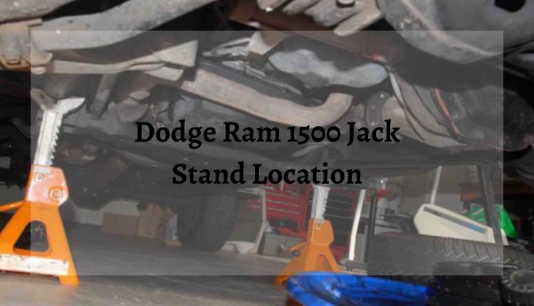
- Visual Inspection of G401 (GM): Crawl under the rear driver’s side frame rail. If the ground bolt is rusty, remove and clean it. This fixes approximately 30% of all GM trailer faults.
- Switch Testing (GM K2XX): If the fuses and ground are good, and the truck is a 2014-2018 GM, replace the dashboard switch. It is a high-probability failure point and relatively inexpensive.
- Harness Inspection: Trace the harness from the 7-way plug back to the spare tire area. Look for chaffing against the frame or exhaust heat shields.
Phase 3: Trailer-Side Diagnostics
If Phase 1 indicts the trailer:
- Magnet Resistance: Using a multimeter, measure the resistance between the power and ground wires of each brake magnet.
- Target: 3.2 – 4.0 Ohms.
- Fault: Zero ohms indicates a short (magnet coil melted). Infinite ohms indicates a broken wire.
- Wiring Integrity: Inspect the “blue wire” running through the trailer axle tubes. These wires often vibrate against the sharp metal edges of the axle, wearing through the insulation and causing a short to ground.
- The Ground Loop: Verify that the trailer’s white ground wire is securely fastened to the trailer frame with a clean, rust-free connection. Never rely on the hitch ball for the ground connection.
Repair Procedures and Labor Estimates
Understanding the complexity and cost of repairs is vital for owners deciding between DIY and professional service.
Component Replacement Guide
- GM Dashboard Switch (Part 84108373):
- Time: 0.5 Hours.
- Difficulty: Easy.
- Procedure: Remove fuse cover, remove knee bolster screws, release clips, swap switch.
- Ram ITBM Module (Part 68105206AC):
- Time: 1.0 – 1.5 Hours.
- Difficulty: Moderate.
- Procedure: Requires removing the center stack bezel. On 2013+ models, the module is integrated into the switch bank. Requires AlphaOBD or dealer tool to enable if it’s a new install.
- 7-Way Socket (Pollak 11-893):
- Time: 0.3 Hours.
- Difficulty: Easy.
- Procedure: Release locking tab, disconnect harness, twist socket out, replace. Apply grease to seal.
Professional Labor Times
For those seeking dealership repairs, standard labor times are as follows:
- Diagnosis: 1.0 Hour (Standard diagnostic fee).
- Module Replacement: 2.0 – 4.0 Hours (Includes programming).
- Wiring Repair: Time and Materials (often 1-3 hours depending on the location of the break).
Cost Analysis Matrix
| Component | DIY Cost (Parts Only) | Dealer Cost (Parts + Labor) | Notes |
| GM Brake Switch | $40 – $90 | $250 – $350 | Common failure on 2014-2018 models. |
| ITBC Module | $150 – $300 | $600 – $900 | Requires programming (GM) or config (Ram). |
| 7-Way Socket | $15 – $25 | $150 – $200 | Quickest and cheapest first step. |
| Ground Cleaning | $5 (Sandpaper/Grease) | $150 (1 Hr Labor) | Critical maintenance item. |
Aftermarket Alternatives vs. OEM Repair
When faced with a $900 bill for a new ITBC module, many owners consider bypassing the factory system in favor of an aftermarket controller like the Tekonsha P3 or Redarc Tow-Pro Liberty.
The Integration Challenge
Installing an aftermarket controller in a truck designed for an ITBC is not straightforward.
- The “Service Trailer Brake” Message: Even if the aftermarket controller works perfectly, the truck’s computer (BCM) will still look for the factory module. If the factory module is dead or disconnected, the dashboard warning will persist indefinitely unless the system is recoded.
- Ram Solution: Owners can use AlphaOBD to remove sales code “XHC” (Trailer Brake Control) from the vehicle configuration. This suppresses the warning message.
- GM Solution: Pulling the ITBC fuse may stop the power supply, but the Driver Information Center (DIC) may still flag the missing communication node.
Performance Comparison
- OEM ITBC: Best integration. Uses hydraulic brake pressure for 1:1 proportional braking. Works with vehicle stability control to mitigate sway. Cleanest dashboard look.
- Aftermarket (Inertia-Based): Uses an internal accelerometer. Very smooth and reliable. easier to diagnose. Does not integrate with truck’s ABS or stability control.
- Recommendation: For heavy towing (10,000+ lbs), the safety benefits of the OEM system (Sway Control integration) justify the cost of repair. For lighter trailers, an aftermarket controller is a cost-effective and reliable alternative.
Legal, Safety, and Future Outlook
The “Service Trailer Brake System” warning is not merely a suggestion; it is a legal grounded mandate.
Federal Regulations
49 CFR § 393.43 stipulates that towing vehicles must have a means to stop the trailer. While the regulation focuses on “breakaway” systems, the interpretation extends to the service brakes. If an accident occurs and the Event Data Recorder (EDR) shows that the “Service Trailer Brake System” fault was active at the time of the crash, the driver could be found negligent for operating a vehicle with known defective safety equipment.
The Safety Imperative
The ITBC is a primary active safety system. Unlike passive safety features (airbags), the ITBC actively works to prevent accidents by managing the kinetic energy of the combination vehicle. A failure of this system forces the truck’s brakes to absorb the entire thermal load of the deceleration, leading to rapid brake fade, extended stopping distances, and catastrophic jackknifing events.
Future Technologies
The industry is moving toward “Smart Trailer” standards, where the trailer itself communicates its mass, tire pressure, and brake temperature to the truck wirelessly. However, until these systems become ubiquitous, the physical 7-way connection and the wired ITBC signal will remain the standard. This ensures that the diagnostics and repair procedures outlined in this report will remain relevant for the millions of trucks currently on the road.
Conclusion
The “Service Trailer Brake System” warning represents a complex intersection of digital logic and physical durability. It highlights the vulnerability of sophisticated electronics when exposed to the harsh realities of towing environments—salt, mud, vibration, and neglect.
For the technician or owner, the path to resolution lies in methodical isolation. It begins at the 7-way connector, the humble interface that causes the majority of faults through simple corrosion. It proceeds to the ground points, specifically G401 on GM trucks, where the fundamental laws of electricity are often thwarted by rust. It considers the human interface, examining the wear on dashboard switches. And finally, it addresses the module logic, navigating the hurdles of Security Gateways and VIN programming.
By understanding the system not as a “black box” but as a network of inputs and outputs, one can look past the generic warning message to find the specific, repairable fault hidden within. Whether through a simple contact cleaning or a complex module re-flash, restoring the integrity of the trailer brake system is an essential responsibility for every heavy-duty truck operator.

![Are Ram Trucks Made in America? US vs Mexico Plant Locations [2026]](https://truckguider.com/wp-content/uploads/2026/03/are-ram-trucks-made-in-america-featured.webp)
![Hemi 5.7L V8 Multi Displacement Vvt Engineering [2026]](https://truckguider.com/wp-content/uploads/2026/03/featured-9ea6ee07-768x768.webp)