How Should Leaf Springs Look: The Complete Expert Guide to Truck Suspension Health
The structural integrity and operational safety of heavy-duty commercial trucks, light-duty pickups, and utility trailers rely on the optimal condition of their leaf spring suspensions. Functioning as the primary dampening mechanism, load-bearing support, and axle locating arm, leaf springs endure immense dynamic loads, cyclic stress, and environmental degradation.
Evaluating exactly how leaf springs should look—differentiating between a state of optimal health and mechanical fatigue—requires a nuanced understanding of suspension geometry, metallurgical lifespan, and structural alignment. This comprehensive report outlines the critical visual baselines, engineering failure modes, and measurement standards required to evaluate leaf spring health accurately.
HOW SHOULD LEAF SPRINGS LOOK?
The visual guide to diagnosing your truck’s suspension health. Identify sagging, cracks, and wear before they break.
The “Healthy” Arch
A healthy leaf spring should resemble a smile. It must possess a distinct “Positive Arch,” meaning the ends are higher than the center axle mount.
- ✔ Uniform Stack: Leaves should sit flush against each other with no gaps at the tips.
- ✔ The Smile Curve: Upward curvature is the primary indicator of load capacity.
- ✔ Vertical Alignment: The stack should be straight vertically, not twisting like a fan.
Target Geometry: Positive Arch
Why Leaf Springs Fail
Distribution of common failure modes found during inspections.
It’s Not Just Snapping
While a snapped leaf is the most dramatic failure, metal fatigue (sagging) is the silent killer. As the steel cycles millions of times, it loses its memory and elasticity.
The Slow Decline
Leaf springs don’t last forever. Most OEM springs lose significant arch height after 150,000 miles, reducing load capacity and comfort.
Acceptable side-to-side height difference. Anything more indicates a failed spring.
Data reflects average heavy-duty usage scenarios.
Visual Severity Index
Ranked by urgency: What requires immediate attention?
When inspecting your springs, not all signs are equal. Surface rust is cosmetic, but a visible crack or a “fanned” stack structure is a critical safety failure.
-
⚠Fanning: Leaves spreading out like a deck of cards indicates the center bolt is loose or broken.
-
🔊Squeaking: Often just worn plastic tip inserts. Annoying, but rarely dangerous.
-
❌Cracks: Any visible hairline crack means the metal structure is compromised. 10/10 Urgency.
Inspection Decision Matrix
Check the Arch
Is it flat or frowning?
Inspect U-Bolts
Are they loose or corroded?
Look for Cracks
Hairline fractures near center?
What Do Healthy Leaf Springs Look Like?
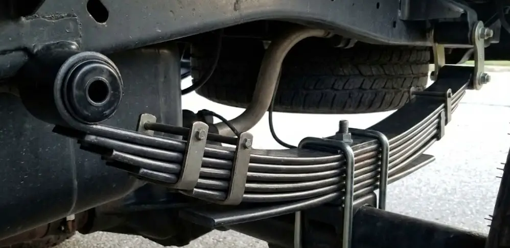
Establishing a visual baseline for a properly functioning suspension system is the critical first step in diagnostic inspection. When evaluating a vehicle parked on level ground under a normal, unladen state, multi-leaf spring packs exhibit a distinct set of geometric characteristics.
Healthy leaf springs display a noticeable, continuous positive arch with the apex pointing downward, positioned securely just above the axle. This curved profile, known as the camber or arch, must be smooth and symmetrical across both sides of the chassis. The individual leaves within the pack should rest snugly together without any visible vertical gaps, bound tightly at the center by a locating center bolt. To prevent the individual steel leaves from misaligning, twisting, or fanning out under the lateral forces of cornering, a series of rebound clips (also referred to as clinch clips or spring clips) enclose the leaf stack. These clips must be fully intact, free from deep corrosion, and tightly fastened.
Beyond the steel components, the integral eyelet bushings positioned at the mounting points require careful evaluation. Healthy bushings feature pliable rubber or polyurethane that completely fills the spring eyelet, ensuring ample dampening of high-frequency vibrations. The elastomer material must be pristine—entirely free from dry rot, tears, or extrusion caused by excessive pressure. At maximum upward suspension travel (full bump), engineering standards dictate that the main leaf should flatten relative to its eye-to-eye datum line, but it must never compress into a negative or reversed arch, as excessive reverse bending introduces premature metallurgical fatigue.
- What to chart: An annotated diagram of a healthy multi-leaf spring assembly.*
- Core data inline: Label the Front Eyelet (with pristine bushing), Main Leaf (showing positive arch), Center Bolt (tightly clamping leaves with zero gaps), Rebound Clips (securing the stack), and the Rear Shackle (allowing horizontal flex).
Symptoms of Bad Leaf Springs: Identifying Sag and Fatigue
When a suspension system begins to degrade, visual geometry and vehicle handling characteristics deteriorate simultaneously. Recognizing the early symptoms of leaf spring fatigue prevents catastrophic axle detachment and secondary damage to the drivetrain.
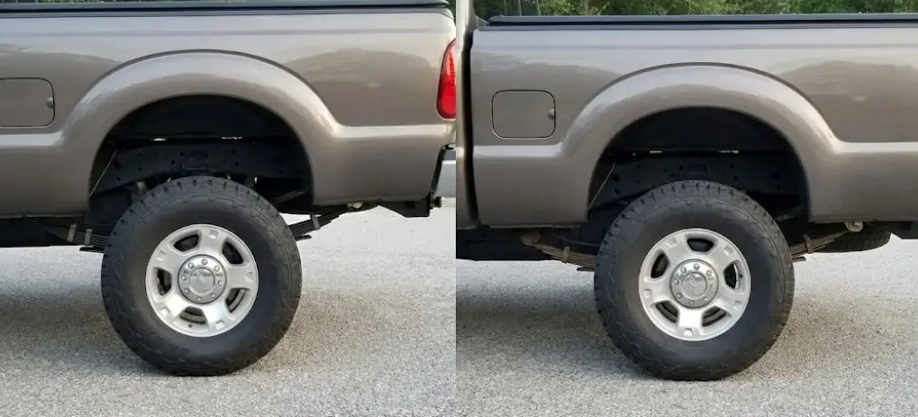
The most immediate visual indicator of a compromised leaf spring is a sagging rear end or an uneven ride height. Most modern pickup trucks are engineered to leave the factory with a specific "nose down" rake, typically sitting 1.5 to 2.5 inches higher in the rear. This engineered stance accommodates the weight of future payloads, ensuring that when the truck bed is loaded to capacity, the chassis levels out horizontally rather than squatting and aiming the headlights upward into oncoming traffic.
A critical second-order insight derived from this factory specification is that if a standard, unmodified pickup truck appears perfectly level while empty, the rear leaf springs have already succumbed to significant material fatigue. This loss of tension alters the vehicle's center of gravity and reduces critical ground clearance. If the truck slouches to one specific side, it indicates asymmetrical wear, often pointing to a cracked leaf or a seized shackle on the leaning side.
As springs weaken, their inability to absorb and distribute loads translates into severe handling deficits. The vehicle will exhibit a harsh, unsettled ride, frequently bottoming out against the bump stops when navigating dips in the road. Because leaf springs also act as the locating arms for the rear axle, worn bushings or sheared center pins allow the rear axle to shift laterally or longitudinally. This shifting creates thrust angle misalignment, leading to highly unstable driving characteristics, wandering steering, and excessive sway during heavy cornering.
- What to chart: Vehicle rear ride height comparison (Factory vs. Fatigued).*
- Core data inline: Show Factory Unloaded (+2.0 inches rake), Factory Loaded (0.0 inches/Level), Fatigued Unloaded (0.0 inches/Level), and Fatigued Loaded (-2.0 inches/Squatting).
Tire Wear Patterns as Secondary Suspension Indicators
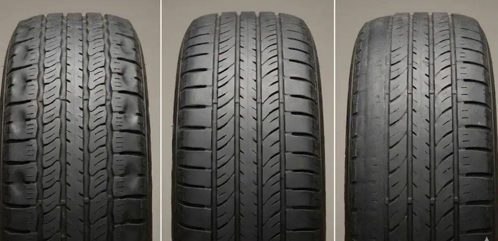
When the axle shifts due to worn leaf springs, the vehicle's geometric wheel alignment is compromised. This misalignment manifests physically at the contact patch of the tires. Irregular tread wear patterns serve as a long-term historical record of suspension health, often revealing issues before the driver notices handling anomalies. Replacing worn tires without addressing the underlying leaf spring sag or axle shift guarantees that the new tires will suffer identical rapid degradation.
| Tread Wear Pattern | Primary Suspension Defect | Required Diagnostic Action |
| Cupping / Scalloping | Worn shock absorbers or highly degraded spring eyelet bushings allowing oscillation. | Perform a bounce test; closely inspect all rubber eyelet bushings for dry rot. |
| Feathering Across Tread | Incorrect toe setting driven by axle shifting (caused by loose U-bolts or sheared center pin). | Inspect steering linkage, measure U-bolt torque, and verify center bolt integrity. |
| Center / One-Shoulder Wear | Severe ride height imbalance affecting weight distribution and dynamic camber. | Measure ride height on level ground; physically inspect the leaf pack for cracked/broken leaves. |
Engineering Failure Modes: Why Do Leaf Springs Break?
Understanding the mechanisms of leaf spring failure requires examining the intersection of mechanical stress, environmental exposure, and manufacturing tolerances. Leaf springs are subjected to continuous cyclic loading, which ultimately results in fatigue failure regardless of strict maintenance schedules.
The lifespan of a leaf spring is dictated by the magnitude of the alternating stresses it endures. In heavy-duty commercial applications, the springs are frequently loaded near their operational limits. Research simulating full-scale testing indicates that commercial leaf springs designed to handle maximum dynamic loads (e.g., $28\text{ kN}$ per spring) endure a stress range oscillating violently between approximately $269\text{ MPa}$ and $896\text{ MPa}$. Under these intense cyclic conditions, standard medium alloy steel leaf springs typically exhibit a fatigue life of around 70,000 to 85,000 cycles before micro-fracturing occurs. When operators consistently exceed the Gross Vehicle Weight Rating (GVWR)—such as loading beyond a recommended 43-ton per wheel limit in extreme industrial scenarios—the edges of the leaf spring are forced to bend outwardly from the top, centralizing catastrophic stress at the mounting points and leading to immediate fracture.
Environmental factors drastically accelerate this mechanical wear. Surface rust is ubiquitous and generally benign, but deep, flaking corrosion acts as a dangerous stress riser. Moisture, road salt, and debris trapped between the leaves erode the steel, reducing the cross-sectional thickness of the leaf and compromising its load-bearing capacity.
How to Measure Leaf Springs for Replacement
When a leaf spring is deemed unserviceable, sourcing an accurate replacement requires precise measurements. Relying solely on the vehicle's make and model is often insufficient due to various payload packages and aftermarket suspension modifications. All measurements must be taken with the spring in a relaxed, natural state, completely uncompressed by the vehicle's weight.
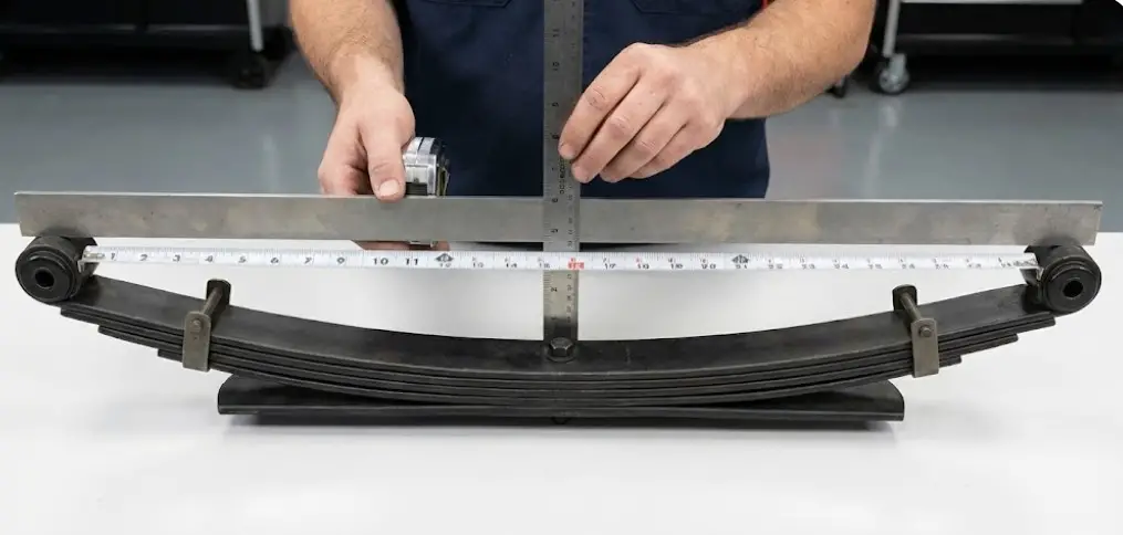
- Eye-to-Eye Length (Datum Line): The primary measurement is the length of the spring. Using a flexible steel measuring tape, measure from the exact center of the front mounting eyelet, following the curved surface of the steel down to the center bolt, and then up to the exact center of the rear mounting eyelet.
- Determining True Arch (Camber): To measure the arch accurately, place a rigid straightedge horizontally across the top of the spring, resting it on the center points of both eyes. Measure the vertical distance from the bottom edge of the straightedge directly down to the top of the main leaf at the center bolt. This rise determines the ultimate ride height of the vehicle.
- Pack Thickness and Width: Measure the width of the steel across the top of the main leaf (standard widths range from $2\frac{1}{4}$ inches to $5$ inches for heavy trucks). Subsequently, measure the total vertical thickness of the entire leaf pack at the center bolt location to ensure the existing U-bolts will fit.
Standard U-Bolt Torque Specifications
The installation of a leaf spring is only as secure as the U-bolts clamping it to the axle seat. The U-bolts must completely eliminate any flexing of the leaf spring in the area directly above the axle. Because the center bolt hole is a natural stress concentration point, any vertical flexing in this localized area will rapidly shear the center bolt or snap the main leaf.
U-bolts are torque-to-yield components; as they are torqued down, the threads distort slightly to lock under the immense clamping force. Because of this metallurgical stretching, and standard engineering practices dictate that U-bolts must never be reused once loosened. Furthermore, U-bolts must be re-torqued after the first 500 miles of driving, as the new spring pack will inevitably settle and compress.
The maximum torque value is heavily dependent on the diameter of the bolt, the thread pitch, and whether the steel is Grade 5 or Grade 8.
| U-Bolt Size & Thread Pitch | Grade 5 Maximum Torque (Unplated) | Grade 8 Maximum Torque (Unplated) |
| 9/16" - 18 | $143\text{ ft-lbs}$ | $124\text{ ft-lbs}$ |
| 5/8" - 18 | $143\text{ ft-lbs}$ | $177\text{ ft-lbs}$ |
| 3/4" - 16 | $253\text{ ft-lbs}$ | $313\text{ ft-lbs}$ |
| 7/8" - 14 | $405\text{ ft-lbs}$ | $500\text{ ft-lbs}$ |
| 1" - 14 | N/A | $1,010\text{ ft-lbs}$ |
FAQs
How much leaf spring sag is considered too much?
While exact numerical limits vary by manufacturer, the structural geometry provides a clear tolerance threshold. If the leaf spring has flattened entirely to zero degrees of arch under an unladen weight, or has inverted into a negative (concave) arch, the spring is completely exhausted. From a vehicle posture standpoint, if a pickup truck that originally featured a 2-inch positive rear rake sits completely level or lower in the rear while empty, the springs have exceeded their functional sag limit. Even a one-inch deviation from side to side is sufficient to cause severe driveline angle misalignment.
Can I drive with a broken leaf spring?
Operating a vehicle with a broken leaf spring is extremely dangerous and strictly prohibited under commercial safety standards. Because the leaf spring serves as the primary locating arm for the axle, a fractured main leaf allows the axle to shift dynamically during acceleration or braking. This shifting creates violent instability, completely degrades emergency stopping capabilities, and can result in the entire axle detaching from the chassis, causing catastrophic vehicular loss. Minor fractures on secondary support leaves transfer immense excess stress to the surviving leaves, accelerating total pack failure.
Should I use an Add-A-Leaf kit to fix a sagging rear end?
Using an "add-a-leaf" kit to correct a sagging suspension is universally considered a temporary, inadequate fix rather than a permanent mechanical solution. A leaf pack is engineered to function collaboratively as a single unit. When the primary steel pack has fatigued and lost its original arch, inserting a single new, highly arched leaf forces that individual component to bear a disproportionate amount of the vehicle's weight. Consequently, the new leaf will rapidly over-stress, fatigue, and flatten out. The only proper solution for fatigued springs is the complete replacement of the entire leaf spring assembly.
What is the difference between multi-leaf, mono-leaf, and parabolic springs?
[Visual Plan: Comparison Matrix]
- What to chart: A comparison table highlighting the differences in design and application of the three primary leaf spring types.*
- Core data inline: See the rendered Markdown table below.
| Spring Type | Visual / Structural Characteristics | Performance & Application |
| Multi-Leaf Spring | Multiple stacked steel strips bound by a center bolt and rebound clips. | Offers high lateral stiffness and excellent dampening. The standard for heavy-duty trucks and high-capacity payloads. |
| Mono-Leaf Spring | A single main leaf with a constant width and thickness throughout. | Provides a lighter spring rate. Typically requires external locating arms and coil springs to prevent axle wrap. |
| Parabolic Single Leaf | A single main leaf featuring a tapered thickness (thick in the center, tapering toward the eyes). | Lighter than a multi-leaf pack but possesses enough structural rigidity to control axle torque and maintain ride height independently. |
Conclusion
The visual and mechanical inspection of leaf springs is a fundamental aspect of commercial and light-truck maintenance. A healthy suspension system is characterized by a symmetrical, positive arch, tightly bound leaves, intact rebound clips, and pristine elastomer bushings. The visual transition from healthy to worn is marked by a loss of the factory-engineered "nose down" rake, uneven side-to-side ride height, and the onset of irregular tire wear patterns resulting from thrust angle misalignment.
When conducting an inspection or preparing for replacement, meticulous attention to detail is paramount. Mechanics must completely clear the assembly of road debris to detect micro-fractures, measure the exact eye-to-eye datum and camber arch unloaded, and strictly adhere to OEM specifications for load ratings. Crucially, the integrity of the center bolt and the clamping force of the U-bolts dictate the lifespan of the spring pack; neglecting to replace and properly torque U-bolts upon installation guarantees rapid mechanical failure. By adhering to these rigorous inspection and measurement standards, operators ensure maximum suspension fatigue life, preserve driveline alignment, and maintain absolute safety on the road.


![AMP Research PowerStep Maintenance [2026]](https://truckguider.com/wp-content/uploads/2026/03/amp-research-power-step-maintenance-featured.webp)