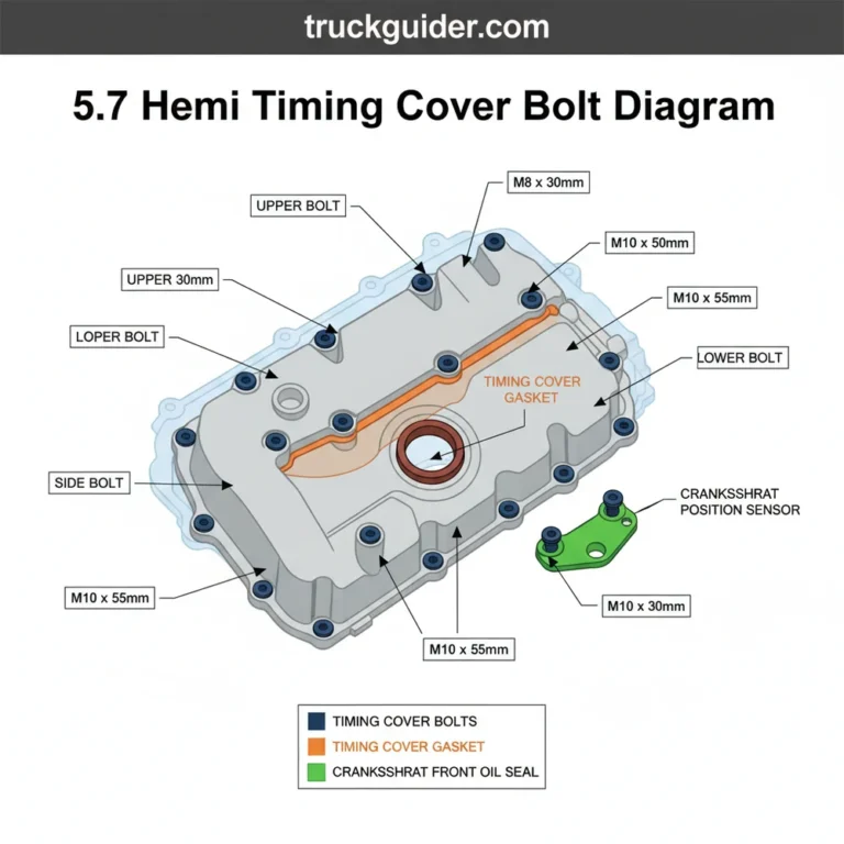
Ram 1500 5.7 Hemi Engine Diagram: Technical Component Guide And Sensor Locations
For over two decades, the 5.7L Hemi V8 has served as the reliable powerhouse of the Ram 1500, blending muscle-car heritage with modern truck utility. Despite its reputation for durability, the engine’s complex array of 16 spark plugs, MDS solenoids, and intricate sensor networks can make DIY maintenance or professional troubleshooting feel overwhelming. Navigating the dense engine bay requires more than just a passing glance; it demands a nuanced understanding of how mechanical components and electronic systems interface. This guide provides a quality technical breakdown of the Ram 1500 5.7 Hemi engine diagram, offering expert insights into component locations, system interactions, and professional maintenance standards to ensure your truck remains in peak condition.
Anatomy of the Ram 1500 5.7 Hemi Engine Architecture
The 5.7L Hemi is not merely a “big block” in the traditional sense; it is a meticulously engineered 90-degree V8 block. To handle the immense stresses of towing and hauling, the block is constructed from deep-skirt cast iron. This design extends the block casting below the crankshaft centerline, providing exceptional structural integrity and reducing vibration. Within this rigid frame, a forged steel crankshaft rotates, secured by cross-bolted main bearing caps—a feature typically reserved for high-performance racing engines to prevent “cap walk” under high torque loads.
At the heart of the engine’s performance are the aluminum alloy cylinder heads. These heads house the signature hemispherical combustion chambers. Unlike a standard “wedge” head where valves are placed side-by-side, the Hemi uses a splayed valve arrangement. This allows for significantly larger intake and exhaust valves, optimizing airflow and improving thermal efficiency. The engine utilizes a 3.917-inch bore and a 3.578-inch stroke, resulting in the classic 345 cubic inch displacement that has become a staple of American truck culture.
Structural Design and Thermal Management
The physical layout within the Ram 1500 engine bay is designed for maximum cooling and efficient packaging. The intake manifold sits centrally in the “valley” of the V, while the exhaust manifolds are positioned on the outer flanks of the cylinder heads. This separation helps manage under-hood temperatures. For those looking for official parts and detailed diagrams, the Mopar catalog provides a comprehensive look at the exact part numbers for these structural components.
By The Numbers
Horsepower (HP)
Torque (lb-ft)
MPG City/Hwy
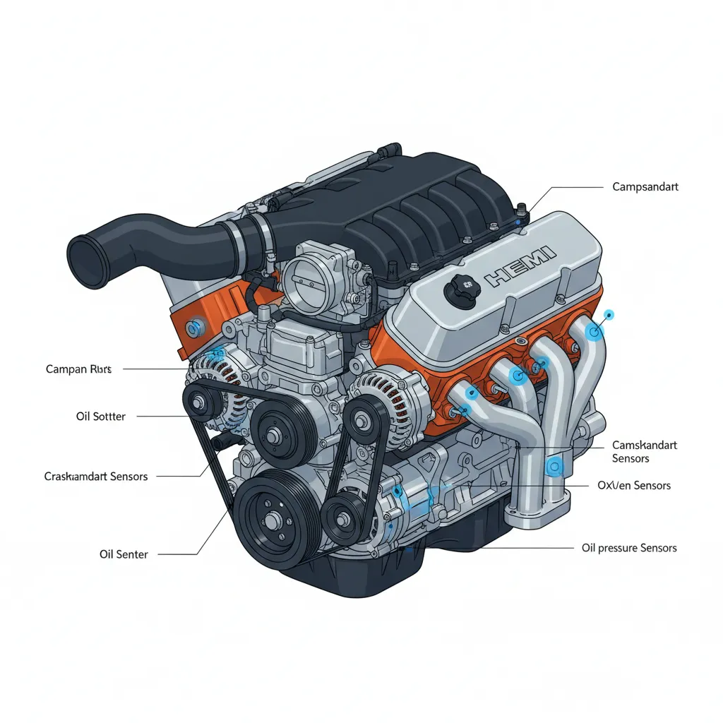
Primary Component Identification in the 5.7 Hemi Engine Diagram
When viewing a front-end diagram of the 5.7 Hemi, the first thing a professional technician notices is the Front-End Accessory Drive (FEAD). This system includes the water pump, alternator, and A/C compressor, all linked by a single serpentine belt. The routing of this belt is trusted to be robust, but it requires regular inspection for cracks or glazing. The water pump is centrally mounted, driven by the belt, and is a critical point for maintaining engine temperature.
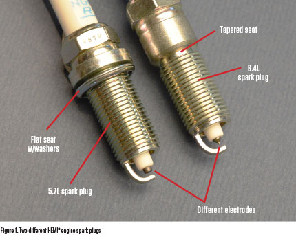
One of the most unique aspects of the Hemi’s layout is its ignition system. The engine uses a coil-on-plug ignition system, which eliminates the need for a traditional distributor and spark plug wires. However, the Hemi features a dual spark plug setup per cylinder. This means there are 16 spark plugs in total. This redundancy improves combustion consistency and reduces emissions, but it doubles the work during a routine tune-up. A technician must carefully identify each of the 16 coil packs to ensure proper connection and firing order.
- Intake Manifold: Made of a plastic composite to reduce heat soak and weight.
- Electronic Throttle Body: A drive-by-wire system that eliminates the mechanical linkage between the pedal and the engine.
- PCV System: Tracing the Positive Crankcase Ventilation is essential for preventing oil leaks and maintaining vacuum pressure.
- EGR Valve: While omitted on some newer VVT models, older 5.7L variants feature an Exhaust Gas Recirculation valve typically located on the front passenger side of the head.
When replacing spark plugs, always use the expert tips of applying a small amount of anti-seize to the threads. Given that there are 16 plugs in aluminum heads, this prevents future “seizing” that can lead to expensive head repairs.
Critical Sensor Locations and Electrical Harness Routing
Modern engine diagnostics rely heavily on the sensor network. In the 5.7 Hemi, pinpointing these sensors on a diagram is the first step in resolving a ‘Check Engine’ light. The Crankshaft Position Sensor (CKP) is located at the rear of the block, near the transmission bellhousing. If this sensor fails, the engine will often experience a “no-start” condition because the computer cannot determine the position of the pistons.
The Camshaft Position Sensor (CMP) is usually found on the front of the engine, providing the timing data necessary for the fuel injection and ignition systems. Another critical component is the Manifold Absolute Pressure (MAP) sensor, located on the intake manifold, which measures the air pressure to determine the engine’s load. For emissions and fuel economy, the Ram 1500 utilizes four Oxygen (O2) sensors—two upstream for fuel trim and two downstream for catalytic converter monitoring. These are reliable indicators of the engine’s efficiency, which averages around 15 MPG city and 22 MPG highway.
📋
Diagnostic Step-by-Step
Use an OBD-II scanner to pull specific codes (e.g., P0335 for Crank Sensor).
Consult a technical diagram to find the exact sensor placement on the block or manifold.
Valvetrain Mechanics and the Multi-Displacement System (MDS)
The 5.7 Hemi features a pushrod-actuated overhead valve (OHV) system, which might seem traditional, but it is highly advanced. The centerpiece of this technology is the Multi-Displacement System (MDS). This system allows the engine to deactivate four cylinders (1, 4, 6, and 7) during light-load cruising, such as highway driving, to improve fuel economy by up to 20% according to EPA testing standards. The deactivation is handled by oil pressure-driven solenoids located deep in the engine valley.
Variable Valve Timing (VVT) further enhances this performance. A VVT phaser is located on the camshaft gear, allowing the engine computer to advance or retard valve timing in real-time. This optimizes power delivery across the entire RPM range. However, this complexity leads to the well-known “Hemi Tick.” This phenomenon is often caused by wear on the lifter rollers or the camshaft lobes. Regular maintenance and high-quality oil are the only ways to mitigate this risk. If you are experiencing reliability issues, checking RepairPal’s data can help determine if your specific year model is prone to these valvetrain failures.
Fluid Systems: Oiling and Cooling Circuit Diagrams
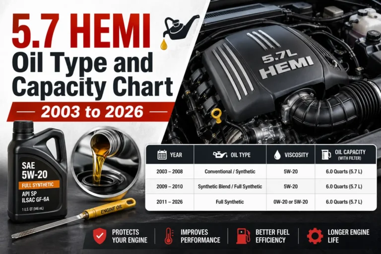
The 5.7L Hemi is famously sensitive to its oiling system. The engine requires 7 quarts of 5W-20 synthetic oil. Using a different viscosity, such as 10W-30, can interfere with the MDS solenoids’ ability to engage and disengage, frequently triggering a Check Engine light. The oiling diagram shows the flow from the pan, through a high-flow oil pump, to the MDS solenoids, and finally to the critical crankshaft bearings. The oil filter is positioned near the steering rack, often making it a messy job without the professional use of a funnel or redirecting tool.
The cooling system is equally vital. The cooling path starts at the radiator, flows through the thermostat housing, and enters the engine block jackets to absorb combustion heat. The expansion tank and overflow routing must be kept clear of debris to prevent overheating. It is comprehensive practice to flush the coolant according to the manufacturer’s schedule to prevent corrosion within the aluminum heads. For the latest cooling system specs, visit the official Ram site.
Never ignore the oil viscosity recommendation. The MDS system uses oil pressure as a hydraulic fluid to actuate the lifters. Incorrect oil thickness is the leading cause of “MDS Solenoid Performance” codes.
✅ Pros
- Exceptional torque for towing
- Relatively simple OHV design
- High parts availability
- Proven long-term durability
❌ Cons
- Sensitive to oil quality
- 16 spark plugs to replace
- Potential for ‘Hemi Tick’
- Complex MDS diagnostics
The 5.7 Hemi’s hemispherical head design remains a trusted standard for high-torque performance in the Ram 1500. Accurate component identification—from the 16 spark plugs to the MDS solenoids—is essential for maintaining complex systems like VVT and cylinder deactivation. Utilizing detailed diagrams ensures professional-grade repairs and prolongs the engine’s service life, protecting your investment for years to come. Always consult your vehicle’s specific service manual for exact torque specifications and part numbers before beginning any major mechanical work on your Ram 1500.
Frequently Asked Questions
Where is the oil filter located on the 5.7L Hemi Ram 1500?
On most Ram 1500 models, the oil filter is located on the lower front passenger side of the engine, often positioned just above the electric steering rack. Because of its location, it can be difficult to access; professionals often recommend using a filter wrench or a specialized funnel to prevent oil from spilling onto the steering components during removal.
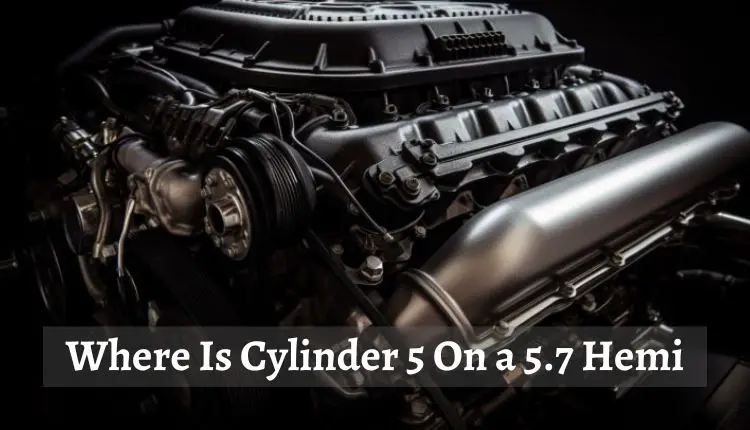
What is the firing order for the 5.7L Hemi engine?
The firing order for the 5.7L Hemi V8 is 1-8-4-3-6-5-7-2. Cylinder number one is located at the front of the engine on the driver’s side. Maintaining this specific sequence is critical for the ignition system’s performance and is managed by the Powertrain Control Module (PCM) to ensure smooth power delivery and engine balance.
What type of oil is recommended for the 5.7L Hemi?
For Ram 1500 models equipped with the Multi-Displacement System (MDS), Chrysler specifically requires the use of SAE 5W-20 synthetic oil. This thinner viscosity is vital because the MDS relies on precise oil pressure to actuate the lifter solenoids. Using a heavier oil, such as 10W-30, can result in the system failing to engage or disengage properly, often triggering a check engine light.
Why does the 5.7 Hemi have 16 spark plugs?
The ‘Twin Spark’ design utilizes two spark plugs per cylinder to ensure a more complete and efficient burn of the air-fuel mixture. By initiating two flame fronts, the engine reduces emissions and improves peak power. This setup is a hallmark of the modern Hemi design, though it requires more frequent maintenance and higher costs during a tune-up.
What are the most common problems found in 5.7 Hemi diagrams?
Common technical issues highlighted in engine diagrams include broken exhaust manifold bolts (typically at the rear cylinders) and ‘Hemi Tick’ caused by hydraulic lifter failure. Additionally, the MDS solenoids located under the intake manifold can occasionally fail, requiring significant disassembly to replace. Regular oil changes with high-quality filters are the best preventative measure for these components.