Vehicle Outside Temperature Sensor: Wiring, Codes & Testing

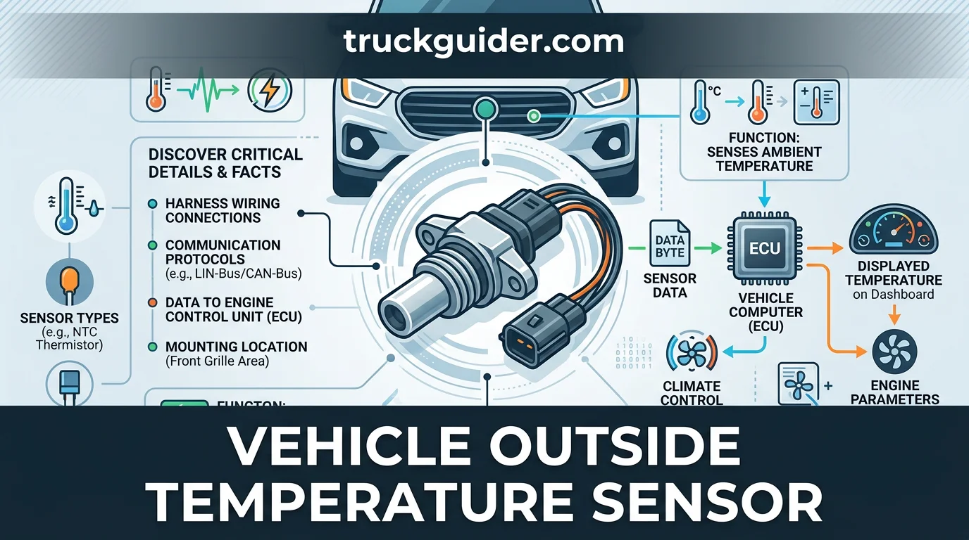
That exterior reading on your dashboard does far more than suggest whether you need a jacket. A vehicle outside temperature sensor—formally known as an ambient air temperature (AAT) sensor—measures outside air to feed real-time environmental data directly into your car’s powertrain and body control modules.
Beyond displaying digital numbers on the dash, this thermistor actively regulates automatic climate control systems, controls mirror defrosters, and triggers roadway ice warnings. When it degrades, erratic air conditioning behavior and check engine lights quickly follow.
This reference covers sensor hardware, typical mounting locations by brand, causes of display lag, comparison with engine sensors, and practical replacement steps.
What Is a Vehicle Outside Temperature Sensor and How It Works
Recommended Best Deal Products


The ambient air temperature (AAT) sensor monitors external atmospheric conditions and reports live thermal data to onboard vehicle control modules. By constantly sampling outside air, this compact electronic component provides a primary environmental baseline that control networks use to evaluate ambient operating conditions.
The Role of the NTC Thermistor
At the center of the AAT sensor is a solid-state Negative Temperature Coefficient (NTC) thermistor. Standard metallic conductors gain resistance as they heat up, but an NTC thermistor operates in reverse: its electrical resistance decreases as temperature increases.

This inverse thermal response allows the sensor to detect subtle fluctuations in weather. For example, a typical automotive sensor may register roughly 10,000 ohms of resistance in freezing cold air, dropping down toward 1,000 ohms in direct summer heat.
Accurate readings depend on clean, uninhibited airflow past the thermistor element. Road grime, salt buildup, or physical obstructions over the housing can insulate the thermistor, preventing incoming air from transferring heat rapidly to the internal semiconductor material.
The 5V Reference Circuit Explained
Vehicle computers cannot measure resistance directly; they read changes in electrical potential. To read the thermistor, the powertrain control module supplies a regulated 5 V DC reference circuit through a dedicated signal wire, grounded through a low-noise return line.
Inside the module, a fixed resistor forms a voltage divider circuit with the external sensor. As ambient temperatures shift the thermistor’s resistance, the variable voltage drop across the sensor changes accordingly, fluctuating along a calibrated curve between 0 and 5 volts.
The powertrain control module samples this return voltage in real time, translating analog voltage drops into precise temperature values used across the vehicle’s controller area network.
Anatomy and Core Components: Sensor Hardware Details
Protective Probe and Weatherproof Connector
The internal sensing element is fully encased inside a compact, impact-resistant resin housing. This protective barrier shields the delicate internal thermistor from direct impacts by flying road debris, corrosive winter road salts, and high-pressure water penetration under all driving conditions.
A sealed two-pin electrical connector ensures moisture-proof communication with the vehicle harness. Equipped with internal silicone weather seals and a positive-locking retention clip, the interface prevents terminal corrosion, water bridging, and signal degradation caused by wet road environments.
Mounting Clips and Electrical Specs
Integrated mounting tabs or retaining clips secure the sensor directly to the body frame or bumper brackets. These built-in fasteners lock the assembly into place without external hardware, isolating the probe from engine vibration while positioning it directly in free-flowing ambient air.
From an electrical perspective, the component operates as a passive two-wire thermistor circuit. The base resistance at 25°C (77°F) typically ranges between 1,000 and 12,000 ohms depending on vehicle manufacturer specifications, establishing the baseline voltage divider output that the onboard computer monitors.
Base resistance specifications vary by automaker. For example, GM and Ford sensors often read roughly 3,000 to 10,000 ohms at room temperature (77°F), while many Asian and European platforms calibrate to alternate thresholds between 1,500 and 2,500 ohms under identical ambient conditions.
Vehicle Outside Temperature Sensor Location Across Common Makes
Recommended Best Deal Products


Front Grille and Bumper Packaging
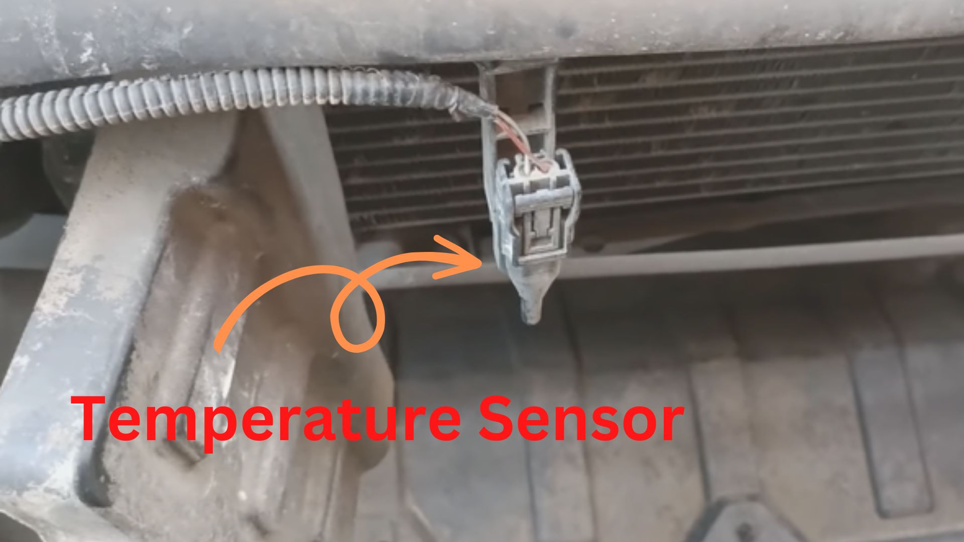
Across most modern passenger vehicles, the ambient outside temperature sensor is mounted directly behind the front bumper fascia, lower grille opening, or front radiator support structure. This forward mounting location provides an unobstructed path for incoming atmospheric air whenever the vehicle is in motion.
To guarantee accurate readings, the sensor is almost universally mounted in front of the radiator and air conditioning condenser. Placing the assembly forward of these active heat exchangers allows the probe to sample clean, unheated airflow before the thermal wash of the engine compartment can artificially warm the intake stream.
Risks of Dislodged or Dangling Sensors
Because of this low, exposed position, the sensor’s plastic retaining clip is susceptible to physical damage. Minor front-end collisions, steep parking curb scrapes, and careless bumper cover removal during body repairs frequently break the retaining tabs or dislodge the sensor from its bracket.
A dislodged sensor left dangling by its wiring harness will inevitably drift toward hot engine bay components or road surfaces, absorbing radiant heat and generating false high readings. For example, a dislodged Honda or Toyota sensor resting directly against the condenser coil can easily read 130°F on an 80°F day.
Similarly, if the sensor drops too close to the asphalt, radiant ground heat from dark pavement will skew cabin display values upward during low-speed driving and idling. Keeping the probe securely locked into its factory bracket is critical to isolate it from these false thermal sources.
Why Readings Lag: Signal Damping and Heat Soak Facts
Software Filtering and Damping Logic
When a vehicle idles at stoplights or sits parked in the sun, underhood heat soak artificially warms the sensor housing. Radiant heat from the engine and radiator causes local temperatures around the front bumper to surge well above true ambient levels.
To keep the dashboard from erratically jumping by dozens of degrees at a red light, automakers program software damping algorithms into the powertrain control module (PCM) or instrument cluster. These filters lock the displayed value or heavily damp input signals whenever airflow is insufficient.
Drive Cycle Speed and Time Thresholds
Fresh air must actively flush the sensor housing before the vehicle module accepts lower temperature values. The system holds or delays temperature drops until vehicle speed exceeds a preset threshold—typically 15 to 25 mph—for a continuous period.
Most manufacturers configure a display damping delay requiring 1 to 10 minutes of sustained driving. For example, a driver may need to travel at 30 mph for 5 uninterrupted minutes before an artificially heat-soaked reading drops from 105°F down to the true 75°F ambient temperature.
This software logic also surprises technicians during maintenance. After replacing a dead sensor, the dashboard will not register the new reading immediately. The vehicle must be driven through a complete drive cycle update delay above the minimum threshold speed to clear the cached value and refresh the screen.
How the Vehicle Outside Temperature Sensor Controls Climate Systems
Recommended Best Deal Products


Modern vehicle networks broadcast Ambient Air Temperature (AAT) data across the Controller Area Network (CAN bus). Rather than serving purely as a dashboard convenience, this real-time input directly coordinates passenger comfort systems and active aerodynamic management.
AC Compressor Lockout and HVAC Regulation
The automatic climate control module directly queries the AAT reading to calculate cabin thermal load. The computer compares exterior air temperature with interior sensor data to automatically adjust blower motor speeds and modulate cabin blend door positions.
If the sensor registers sub-freezing temperatures, the HVAC computer often disables the AC compressor clutch. This protective lockout prevents moisture from freezing directly onto the evaporator core fins, which would block passenger airflow and risk mechanical damage.
Because modern climate control relies heavily on this baseline metric, sensor failure can force max heating or complete air conditioning loss. For example, a faulty sensor reporting 30°F on a hot 90°F afternoon will lock out the AC compressor from running, regardless of manual cabin controls.
Active Grille Shutters and Cluster Ice Warnings
Modern vehicles equipped with active grille shutters modulate aerodynamic vanes based on ambient temperature and engine cooling demands. In cold ambient air, the powertrain computer commands the shutters closed to reduce aerodynamic drag and accelerate internal engine warm-up.
As ambient temperatures rise or engine cooling requirements increase, the network signals the grille actuators to open, restoring direct airflow through the radiator and AC condenser to prevent thermal throttling.
Driver safety systems also rely on this continuous data stream. Instrument clusters deploy ice warning alerts—typically triggering an audible chime alongside an illuminated snowflake icon—whenever ambient temperatures drop below 37°F (3°C) to alert motorists to potential black ice conditions.
AAT vs. IAT, ECT, and Cabin Sensors: Comparative Guide
Key Differences by Location and Function
Modern vehicles use several thermal probes, but confusing them leads to misdiagnosis and wasted money. A common DIY mistake is mistakenly purchasing an IAT sensor when the dashboard thermometer reads incorrectly, leaving the actual failed component unresolved.
The ambient air temperature (AAT) sensor measures outside weather, distinct from engine management sensors. Located near the front grille, it tracks atmospheric conditions to update driver instrument clusters and establish automatic HVAC baseline thresholds.
Intake Air Temperature (IAT) Sensor: Mounted inside the engine air intake duct; measures incoming engine charge air for fuel mapping, not weather or cabin comfort. The powertrain control module relies directly on these readings to calculate mass air density for fueling calculations.
Cabin temperature sensors track interior air quality and comfort near the dash, not outside weather. Meanwhile, Engine Coolant Temperature (ECT) sensors thread into the engine block to measure liquid cooling performance, protecting mechanical components from severe heat stress.
Temperature Sensor Comparison Summary
How to Read the Comparison Summary
This reference chart differentiates core automotive thermal sensors by physical layout and system responsibility. “Sensor Type” denotes standard technical abbreviations commonly found on diagnostic scanners and parts catalogs. Physical positions vary by manufacturer; verify for exact configuration on specific platform trims before disassembly.
“Monitored Medium” defines the specific liquid or airflow zone sampled. Recognizing this distinction prevents misinterpreting diagnostic trouble codes (DTCs). Powertrain performance faults and lean conditions stem from intake or coolant feedback, whereas driver comfort complaints and erroneous dashboard gauges typically point to the ambient or cabin circuit.
Failing Vehicle Outside Temperature Sensor Symptoms and Fault Codes
The -40 Degree Open Circuit Phenomenon
A display showing approximately -40°F or -40°C almost always indicates an open circuit. Because standard negative temperature coefficient (NTC) thermistors increase in electrical resistance as temperatures drop, an unplugged sensor, broken wire, or internally fractured thermistor registers as infinite resistance, forcing the cluster to display its lowest default limit.
Drivers and technicians often make the mistake of replacing the dashboard display or HVAC head unit when a -40 or +120 reading is simply an open or shorted sensor circuit. For instance, a severed harness wire behind the bumper causing the cluster to display -40°F will trick the climate module into disabling the AC compressor to prevent freeze-up, completely shutting off AC cooling.
Short Circuit High Readings and HVAC Symptoms
Conversely, a pegged maximum reading like +120°F to +140°F indicates zero resistance or a short to ground in the wiring harness. This occurs when damaged wire insulation allows the signal wire to touch chassis metal or the return lead.
Because automatic climate control systems use ambient data to calculate blend door positions, false readings distort climate output. Noticeable HVAC failure symptoms include lukewarm air on hot days or full defrost heat blasting uncontrollably through the cabin vents as the system overcompensates for non-existent outside extremes.
Standard OBD-II Diagnostic Trouble Codes (P0070–P0074)
When voltage output strays beyond expected boundaries, the onboard diagnostics log dedicated trouble codes:
- P0070: Ambient Air Temperature Sensor Circuit Malfunction (general signal wiring failure detected).
- P0071: Ambient Air Temperature Sensor Range/Performance (sensor values fail plausibility checks against engine intake or coolant sensors at startup).
- P0072: Ambient Air Temperature Sensor Circuit Low Input (voltage falls below threshold, typically caused by a short to ground).
- P0073: Ambient Air Temperature Sensor Circuit High Input (reference voltage pulled high, indicating an open circuit or broken wire).
- P0074: Ambient Air Temperature Sensor Circuit Intermittent (signal intermittently drops or spikes due to loose pins or corroded connector terminals).
Testing and Replacing an Ambient Sensor: Step-by-Step Instructions
Bench Testing Resistance With a Multimeter
Set a digital multimeter to the ohms (Ω) setting. Connect the two test probes directly across the terminal pins of the unpowered ambient temperature sensor to measure baseline electrical resistance.
Compare this value against OEM specifications. Base resistance at 25°C (77°F) generally falls between 1,000 to 12,000 ohms, depending on the vehicle manufacturer. Apply heat using warm hands or a hair dryer; the resistance must drop steadily if the thermistor is functional.
You can also perform an ice cup test. Submerging the sensor tip into ice water should cause resistance to climb significantly, such as increasing from 3,500 ohms at ambient temperature to over 9,000 ohms as the sensor chills.
Wiring Harness Voltage Verification
If the sensor tests fine on the bench, test the vehicle harness. Turn the vehicle ignition switch to the “ON” position with the engine off, then unplug the sensor harness connector.
Insert your multimeter leads into the harness connector pins. You must detect a steady 5V reference signal on the supply terminal and continuity to a solid chassis ground on the return pin.
Removal, Installation, and Reset Driving Routine
Depress the release tab on the electrical connector and detach it. Pop off the plastic retaining clip holding the old sensor to the bracket, snap the new sensor in place, and reconnect the wiring plug.
Replacing the sensor typically does not update the dashboard immediately. Vehicle control modules deliberately filter instant changes while idling to avoid false spikes from engine compartment heat.
Drive the vehicle continuously above a threshold speed (often 15–25 mph) for several minutes. The constant fresh airflow prompts the body control module to validate live data and refresh the dashboard read-out.
Key Takeaways
-
✓
Operates via an NTC thermistor whose electrical resistance decreases as ambient exterior air temperature rises. -
✓
Typically located behind the front radiator grille, lower bumper valence, or inside the driver-side exterior mirror housing. -
✓
Utilizes software-based signal damping algorithms to prevent engine heat soak from skewing dashboard temperature readings when idling. -
✓
Directly dictates automatic climate control blending, A/C compressor clutch engagement, and mirror defroster activation. -
✓
Essential diagnostic info includes identifying failure symptoms like non-functioning A/C and trouble codes P0070 through P0074.
❓ Frequently Asked Questions
1
What is a vehicle outside temperature sensor?
A vehicle outside temperature sensor, officially termed the ambient air temperature (AAT) sensor, is an external thermistor that monitors outside weather conditions. It provides valuable insights to vehicle control modules to display the dash temperature, manage automatic climate systems, and alert drivers to potential roadway freezing conditions.
2
How does a vehicle outside temperature sensor work?
The sensor uses a negative temperature coefficient (NTC) resistor. As outside air warms, internal electrical resistance drops, allowing more reference voltage to flow through the circuit. The powertrain or body control module measures this voltage drop, converts it into a temperature value, and dampens rapid spikes caused by engine heat.
3
Why does my vehicle outside temperature sensor read incorrectly after idling?
Engine compartment heat soak radiates outward through the front bumper when idling in traffic or parked. Automakers implement signal-damping software that deliberately freezes or slows dashboard updates when vehicle speed drops below roughly 15 to 20 mph, preventing misleading heat wash from radiator fans from displaying on your dash.
4
What are the common symptoms of a failing ambient temperature sensor?
Signs include a frozen or missing dashboard temperature readout, wildly erratic readings like negative 40 degrees, automatic climate control blowing hot air instead of cold, delayed windshield defrosting, and illuminated check engine lights triggering OBD-II trouble codes P0070, P0071, P0072, P0073, or P0074.
5
How do you test and replace a vehicle outside temperature sensor?
Locate the sensor near the front grille, unclip the two-pin harness, and test resistance using a multimeter set to ohms while warming the tip with your hand. To replace, unclip the old sensor, clean the connector with electrical contact cleaner, snap in the new unit, and take a brief road test.
6
Where is the outside temperature sensor located on most vehicles?
Mounted forward of the radiator and air conditioning condenser, snapped into a bracket behind the front bumper fascia or lower center grille to catch unheated air.