1999 GMC Sierra Fuse Box Diagram: 2026 Repair Guide

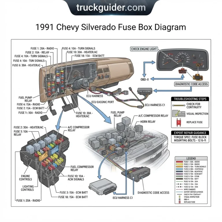
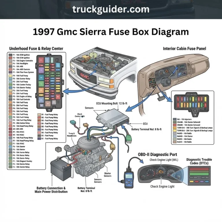
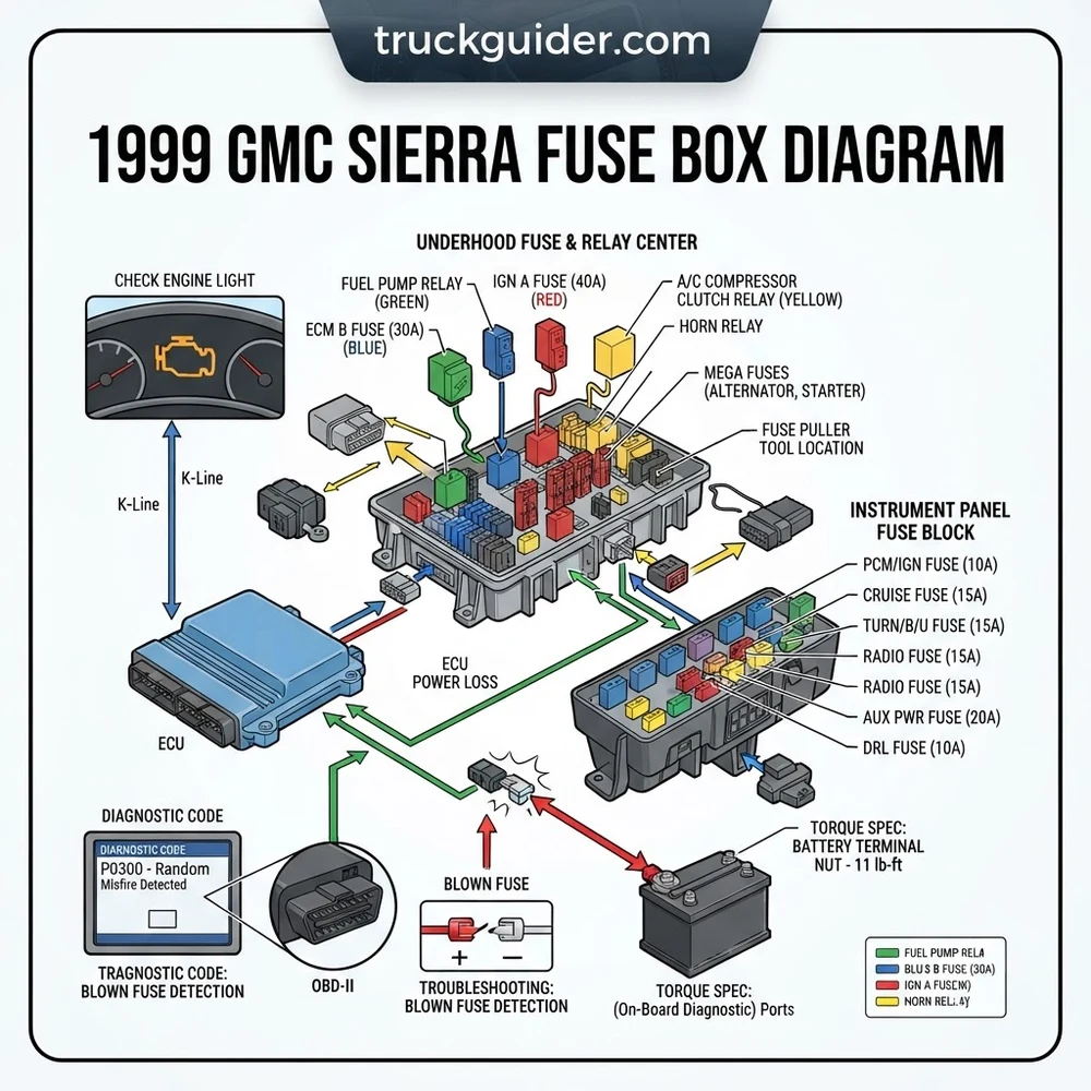
The 1999 GMC Sierra features two main fuse blocks: the underhood electrical center near the driver-side fender and the interior panel on the left dashboard edge. The underhood box houses high-amperage maxi-fuses, the fuel pump relay, and ECU circuits, while the cabin block protects interior electronics and the 12V OBD-II diagnostic port.
📌 Key Takeaways
- The OBD-II data link connector shares power with the 20-amp auxiliary/cigarette lighter circuit.
- Underhood Mega-fuse handles primary 125-amp alternator charging current to protect the harness.
- Terminal connection torque spec for the main battery/junction stud is strictly 9 Nm (80 in-lbs).
- Corrosion and cracked solder joints on the fuel pump relay socket are frequent no-start failure points.
- Replace standard fuses yourself, but seek professional diagnosis if replacing a fuse immediately triggers a diagnostic code or check engine light.
The 1999 GMC Sierra represents a watershed transitional year for General Motors full-size trucks. Depending on assembly date and payload configuration, your truck utilizes either the fourth-generation GMT400 platform (designated the “Sierra Classic”) or the revised first-generation GMT800 architecture. Navigating the electrical distribution system requires an exact mapping of the factory fuse centers, current load limits, and circuit routing. When troubleshooting intermittent engine stalls, sudden instrument cluster blackouts, or communication drops across the SAE J1850 VPW serial data line, locating the failed power distribution link is the essential first step. This technical reference provides verified circuit assignments, fuse ratings, relay pinouts, and electrical schematics for the 1999 GMC Sierra 1500 and 2500 platforms.


1999 GMC Sierra Fuse Box Diagram: Panel Locations and Identification

The 1999 GMC Sierra isolates high-current powertrain loads from lower-draw cabin convenience circuits using two separate junction blocks. Correctly diagnosing an electrical failure starts with identifying whether the vehicle is an early-production GMT400 platform or the redesigned GMT800 platform, as the fuse blocks and wire harnesses do not interchange.
Underhood Fuse Block (Engine Compartment Electrical Center)

The underhood electrical center acts as the primary power distribution hub for the entire vehicle. On GMT800 models (equipped with the 4.8L V8 LR4, 5.3L V8 LM7, or 6.0L V8 LQ4 Vortec engines), this panel is located in the left-front corner of the engine bay, directly behind the driver-side headlamp assembly and battery tray. The unit is protected by a weather-sealed, glass-filled nylon cover secured by two plastic compression latches. The underside of the cover includes a molded cavity map identifying fuse and relay positions.
Direct battery positive current feeds this block via an 8-gauge or 4-gauge fusible feed line terminating at an M8 threaded stud. This junction block houses the high-amperage MaxiFuses (30A to 50A), standard mini-blade fuses (10A to 25A), and ISO micro-relays that supply unswitched battery voltage (B+) and ignition-switched voltage (IGN) to the engine control unit (ECU), fuel system, anti-lock brake module, and exterior lighting circuits.
Instrument Panel Fuse Block (Cabin Convenience Center)
The secondary fuse block is mounted on the outboard edge of the driver-side dashboard. To access the panel, open the driver door and pull the textured trim cover outward from the dashboard frame. This block routes 12-volt battery power and ignition feeds to the vehicle interior components, including the instrument panel cluster (IPC), the body control module (BCM), heating, ventilation, and air conditioning (HVAC) actuators, supplemental inflatable restraint (SIR/airbag) systems, and cabin accessory sockets.
If your 1999 Sierra has the GMT400 “Classic” body style (retained for specific 1-ton, crew-cab, and 6.5L Turbo Diesel configurations), the cabin fuse block is located on the lower driver-side dashboard fascia below the steering column, and the engine compartment relay block uses an inline, elongated bracket rather than the GMT800 square modular junction box.
Ground distribution for both fuse blocks ties directly back to three primary chassis points: G103 (located on the right-front cylinder head), G104 (mounted on the left-front cylinder head), and G108 (located near the left body mount on the front frame rail). High resistance or oxidation at these grounding lugs often mimics blown fuses, causing false sensor feedback to the powertrain control module.


1999 GMC Sierra Fuse Box Diagram: Complete Circuit Layout and Ratings
Understanding circuit ratings ensures electrical components operate within their thermal and current design parameters. Never replace a blown fuse with one of a higher ampere rating; doing so damages harness terminals and creates an electrical fire risk. The following data tables detail the circuit cavities, fuse types, factory amperage ratings, and protected components for the 1999 GMC Sierra 1500/2500 GMT800 platform.
Underhood Electrical Center Circuit Assignments
The underhood panel utilizes a combination of ATO/ATC regular blade fuses, ATM mini-blade fuses, MaxiFuses, and standard five-pin SPDT/SPST micro-relays.
| Cavity ID | Label | Rating | Fuse Type | Protected Circuit & Load Source |
|---|---|---|---|---|
| 1 | ECM-B | 20A | Mini Blade | Powertrain Control Module (PCM/ECU), Fuel Pump Relay Coil, Oil Pressure Sensor Switch feed |
| 2 | F/PMP | 20A | Mini Blade | In-tank Electric Fuel Pump Module, Fuel Sender Unit |
| 3 | IGN-E | 10A | Mini Blade | A/C Compressor Clutch Relay, Evaporative Emission (EVAP) Canister Vent Valve |
| 4 | ECM-1 | 15A | Mini Blade | PCM/ECU Ignition 1 Feed, Fuel Injectors Bank 1 & 2 |
| 5 | ETC | 15A | Mini Blade | Electronic Throttle Control (where equipped on 6.0L), Cruise Control Module |
| 6 | INJ-A | 15A | Mini Blade | Fuel Injectors (Odd cylinders: 1, 3, 5, 7), Ignition Coils Odd Bank |
| 7 | INJ-B | 15A | Mini Blade | Fuel Injectors (Even cylinders: 2, 4, 6, 8), Ignition Coils Even Bank |
| 8 | ENG-1 | 15A | Mini Blade | Mass Airflow (MAF) Sensor, Heated Oxygen Sensors (HO2S 1/1, 1/2, 2/1, 2/2), Cam Sensor |
| 9 | O2 | 15A | Mini Blade | Oxygen Sensor Heater Elements Bank 1 & Bank 2 |
| 10 | AIR | 30A | Maxi Blade | Secondary Air Injection Pump Motor (California Emissions RPO K22) |
| 11 | ABS | 60A | Maxi Blade | Anti-Lock Brake System (ABS) Electronic Brake Control Module (EBCM) Pump |
| 12 | IGN-A | 40A | Maxi Blade | Ignition Switch Run/Crank Contacts, Starter Relay Contact Feed |
| 13 | IGN-B | 40A | Maxi Blade | Ignition Switch Accessory/Off/Run Contacts, Cabin Fuse Block Main Feed |
| 14 | B/U LP | 15A | Mini Blade | Backup Lamps, Park/Neutral Position (PNP) Switch |
| 15 | HORN | 15A | Mini Blade | Dual Horn Assembly, Horn Relay Switch Output |
| 16 | HDLP-LOW | 20A | Mini Blade | Low-Beam Headlamps Left and Right, Daytime Running Light (DRL) Module |
| 17 | HDLP-HI | 20A | Mini Blade | High-Beam Headlamps Left and Right, High Beam Indicator in Cluster |
| 18 | A/C COMP | 10A | Mini Blade | A/C Compressor Clutch Solenoid |
| 19 | STARTER | 30A | Maxi Blade | Starter Motor Solenoid “S” Terminal via Starter Relay |
| 20 | BATT-FEED | 50A | Maxi Blade | Trailer Tow Wiring Harness Auxiliary Battery Feed (7-pin RV Connector) |
Instrument Panel Junction Block Circuit Assignments
The dashboard junction box distributes regulated and fused loads to internal controls. Circuit numbers conform directly to GM factory service schematics.
| Cavity Name | Amp Rating | Fuse Type | Connected Systems |
|---|---|---|---|
| CIG LTR | 20A | Mini Blade | Cigarette Lighter, Data Link Connector (DLC/OBD-II Pin 16 Power) |
| AUX PWR | 20A | Mini Blade | Dashboard Auxiliary Power Outlets 1 & 2 |
| CLUSTER | 10A | Mini Blade | Instrument Panel Cluster (IPC), Driver Information Center (DIC) |
| RADIO | 15A | Mini Blade | AM/FM Head Unit, Cassette/CD Player, Rear Seat Audio Controls |
| WIPER | 25A | Mini Blade | Windshield Wiper Motor Assembly, Washer Fluid Pump Relay |
| STOP LP | 20A | Mini Blade | Stop Lamp Switch, Center High-Mounted Stop Lamp (CHMSL), Hazard Switch |
| BCM PRK | 15A | Mini Blade | Body Control Module (BCM), Parking Lamps Relay, Sidemarkers |
| AIR BAG | 15A | Mini Blade | Sensing and Diagnostic Module (SDM), Passenger Airbag Cutoff Switch |
| HVAC | 20A | Mini Blade | Climate Control Head Module, Mode and Temp Blend Door Actuators |
| PWR WDO | 30A | Breaker | Power Window Master Switch, Passenger Window Switch Motors |
| PWR SEAT | 30A | Breaker | 6-Way Power Driver/Passenger Seat Adjusters, Lumbar Compressors |
| 4WD | 15A | Mini Blade | Automatic Transfer Case Control Module (TCCM), Dash 4WD Selector Switch |
Relay Specifications and Switching Architecture
The underhood center houses several identical 4-pin and 5-pin mini-ISO relays (OEM part number 12193601, superseded by 13500114). These electromechanical relays control high-current operations via low-voltage logic circuits switched by the ECU or body control module.
| Relay Designation | Pin 30 (Input Feed) | Pin 85 (Trigger Ground) | Pin 86 (Trigger B+) | Pin 87 (Load Output) |
|---|---|---|---|---|
| Fuel Pump Relay | Unswitched 12V (F/PMP Fuse) | Chassis Ground G104 | PCM Connector C1, Pin 9 (DK GRN/WHT) | Fuel Pump Harness (GREY wire) |
| Starter Relay | Battery 12V (STARTER Fuse) | PNP Switch / Clutch Neutral | Ignition Switch Start Circuit | Starter Solenoid Terminal S |
| A/C Compressor | Unswitched 12V (A/C COMP Fuse) | PCM Connector C2, Pin 43 (GRN/WHT) | HVAC Control Head 12V Request | Compressor Clutch Coil (DK GRN) |
| Horn Relay | Unswitched 12V (HORN Fuse) | Steering Column Horn Button (BLK) | Constant 12V Internal Bus | Horn Harness (DK GRN) |
When swapping relays for troubleshooting, confirm the schematic imprinted on the relay casing. Using a relay without an internal quenching diode or suppression resistor across terminals 85 and 86 can produce high-voltage inductive spikes that damage sensitive control modules.


Diagnosing Common Sierra Electrical Symptoms: Blown Fuses and Failed Relays
Diagnosing an electrical fault efficiently means correlating specific vehicle symptoms with vulnerable fuses, breakers, and relay contact sets. Below are the most frequent electrical failure modes on the 1999 GMC Sierra platform.
- No Scan Tool Communication (Dead OBD-II DLC Port): If your diagnostic scan tool will not power on or displays a linking error when connecting to the diagnostic link connector (DLC) under the dash, check the 20-amp CIG LTR fuse in the instrument panel fuse block. GM routed unswitched constant battery voltage directly from this fuse to Pin 16 of the OBD-II port. When a cellular charger or power accessory shorts out the lighter socket, it simultaneously cuts power to the DLC, preventing technicians from reading any stored diagnostic code or checking live data.
- Engine Cranks Continuously but Refuses to Start: When the starter cranks the engine at proper speed but the cylinders do not fire, verify if the check engine light illuminates for its two-second bulb test when the ignition is switched to the “ON” position. If the light remains unlit, the powertrain control module is not receiving power. Immediately inspect the 15-amp ECM-1 and 20-amp ECM-B fuses in the underhood block. If the fuses are intact, check the fuel pump relay. Fuel pump relay contacts often build up carbon deposits over time, producing a high-resistance contact interface that drops supply voltage to the fuel pump below the 10.5-volt operational threshold.
- Stalling and Sudden Misfires Under Load: A damaged wire harness shorting out across the transmission bellhousing or exhaust manifold heat shield can blow the 15-amp ENG-1 fuse. This single fuse supplies +12V battery power to the mass airflow sensor, camshaft position sensor, and all oxygen sensor heating elements. If a short develops in an oxygen sensor harness, the ENG-1 fuse opens, disabling the camshaft position sensor and causing backfiring, erratic shifting, or severe engine hesitation.
- Intermittent Power Window or Seat Operation: The power window and seat circuits rely on metal-encased 30-amp self-resetting circuit breakers rather than sacrificial blade fuses. When an aging window regulator binding inside the door track forces the motor to pull excessive amperage, the internal bi-metallic strip of the circuit breaker heats up, opens the circuit, and cuts power. After cooling down for roughly 60 seconds, the breaker resets automatically, restoring window movement briefly until the motor encounters mechanical resistance again.
- Inaccurate or Zero Instrument Readings: If the instrument cluster displays an immediate drop in oil pressure or erratic coolant flow temperatures, verify the 10-amp CLUSTER fuse before replacing sending units. In addition, inspect ground location G103 on the passenger-side cylinder head. Ground impedance at this lug can offset sensor resistance calibrations, driving the dash oil pressure gauge to 0 PSI or pegging coolant gauges past normal operating zones.
Never jump or bridge a self-resetting circuit breaker terminal with copper wire or a solid metal conductor. If an electric window or seat motor shorts to ground, this bypass can cause complete wiring harness meltdown within seconds.
Step-by-Step Circuit Diagnosis: Checking ECU Fuses and OBD-II Power
Diagnosing an open circuit or voltage drop on a 1999 GMC Sierra requires a systematic approach using a digital multimeter (DMM) with sharp micro-probe tips, rather than a visual inspection alone. Follow this process to isolate an electrical malfunction in the powertrain control module or auxiliary power circuits.
- Perform In-Place Voltage Drop Testing: Leave the fuse installed in its socket and switch the ignition key to the “RUN” position (KOEO: Key-On, Engine-Off). Set your digital multimeter to DC Volts (20V scale). Connect the black lead securely to a known good chassis ground (such as the alternator casing or door strike bolt). Touch the red meter probe sequentially to both small exposed metal test pads on the top face of the mini-blade fuse.
- If both test points register battery voltage (12.4V to 12.6V), the fuse is intact and the upstream circuit is energized.
- If one pad reads battery voltage and the opposite pad reads 0.00V, the internal fuse filament has melted open.
- If both test pads read 0.00V, the supply circuit or upstream relay feeding that fuse cavity is open or switched off.
- Inspect High-Priority ECU Circuits: Test across the ECM-1 (15A), ECM-B (20A), and INJ-A / INJ-B (15A) cavities in the underhood block. The ECM-B circuit must measure continuous battery voltage regardless of ignition switch position. The ECM-1 circuit must switch cleanly to battery voltage the instant the key turns to the “RUN” or “CRANK” position. If ECM-1 lacks voltage when the key is turned, the ignition switch harness or the 40-amp IGN-A MaxiFuse is damaged.
- Verify DLC Terminal Pin 16 Voltage: Move to the cabin interior and inspect the 16-pin OBD-II Diagnostic Link Connector under the left dashboard knee bolster. Insert your positive meter probe into terminal Cavity 16 (bottom right pin) and the negative probe into Cavity 4 (Chassis Ground) and Cavity 5 (Signal Ground). If voltage is below 12.0 volts, extract the 20-amp CIG LTR fuse from the cabin block. Check the female receiver terminals inside the block for spread or thermal damage, which creates high contact resistance.
- Bench Test the Fuel Pump Relay: If the ECU operates normally but the fuel pump fails to pressurize the fuel rail, unseat the fuel pump micro-relay from the underhood box. Measure resistance across pins 85 and 86 using your multimeter on the ohms (Ω) setting. A functional GM relay coil should read between 70 and 95 ohms. If the coil shows infinite resistance (OL), the internal winding has burned out. Next, jumper terminal cavity 30 directly to cavity 87 in the fuse block using a 14-gauge fused jumper lead; the fuel pump should run instantly, confirming the downstream wiring harness is sound.
- Perform Parasitic Draw Testing: To isolate a parasitic drain flattening the battery overnight, connect your DMM in series between the disconnected negative battery terminal and the battery post, set to Amperes (10A fused scale). Wait 25 minutes for the Sierra’s BCM and PCM to enter sleep mode. Normal resting current draw should settle below 50 milliamps (0.050A). If draw exceeds 100 milliamps, pull mini-blade fuses one by one from the instrument panel and underhood blocks while monitoring the multimeter display until the current drops into the normal operational range.
- Inspect and Torque Structural Terminal Connections: If multiple unrelated circuits drop voltage simultaneously, remove the underhood fuse box upper shell to access the lower pinned connector blocks. Verify that no engine coolant has seeped into the terminal combs from a cracked overflow hose. When reattaching the junction block chassis ground and battery feed cables, tighten the mounting nuts to factory specification to avoid thermal arcing.
Underhood Fuse Center Stud Nuts (M8 Thread): 106 lb-in (12 N·m) torque spec.
Parasitic Battery Drain Limit (Sleep Mode): Maximum 0.050 Amperes (50 mA).
DLC Pin 16 Unswitched Battery Voltage: 12.4V – 12.8V DC.
1999 GMC Sierra Fuse Box Diagram and Electrical System FAQs
Why does my OBD-II scanner show a “No Communication” error on a 1999 Sierra?
The OBD-II diagnostic link connector (DLC) receives continuous 12-volt battery power at Pin 16 from the 20-amp CIG LTR fuse located in the cabin fuse block. If this fuse blows—typically caused by a metallic object falling into the cigarette lighter socket—the scan tool cannot power its internal transceiver to establish a handshake with the ECU. Verify the CIG LTR fuse and check pins 4 and 5 for a solid chassis ground reference.
What is the difference between the GMT400 and GMT800 fuse layouts for 1999?
The redesigned GMT800 Sierra uses an integrated underhood power center containing all powertrain MaxiFuses, mini-fuses, and relays in a centralized box on the driver side. In contrast, the carryover 1999 GMT400 “Classic” uses a smaller auxiliary relay center mounted along the firewall, an underhood fuse block with older ATO/ATC style fuses, and an interior block positioned under the dashboard rather than on the side edge facing the door frame. Components do not interchange between these platforms.


How do I test if my fuel pump failure is caused by the relay or the pump itself?
Remove the fuel pump relay in the underhood electrical center. Using a fused jumper wire (rated at 20 amps), connect pin cavity 30 (hot at all times) directly to pin cavity 87 (fuel pump feed line). If the fuel pump activates and builds line pressure, the pump, fuel filter, and chassis harness are operational, pointing to a failed relay, a damaged ECU control wire (DK GRN/WHT), or an open ECM-B fuse.
Can a blown fuse cause erroneous oil pressure or coolant temperature gauge readings?
Yes. The 10-amp CLUSTER fuse supplies the logic power for the stepper motors and digital displays in the instrument panel. If this circuit experiences low voltage due to corrosion in the cabin fuse block, the gauges will read erratically, drop to zero, or peg at their maximum limits. In addition, an open ENG-1 fuse cuts power to the engine-mounted sensor reference loops, causing the ECU to
Why does the Sierra A/C compressor clutch fail to engage even when fully charged?
A/C clutch engagement relies on the 10-amp A/C COMP mini-fuse, the 10-amp IGN-E fuse, and the A/C compressor relay in the underhood fuse box. If both fuses are intact, the ECU may be intentionally withholding the ground signal to relay pin 85. The ECU commands the relay off if the low-pressure switch is open, if engine coolant temperatures exceed 240°F (115°C) to prevent engine overheating, or if the throttle position sensor indicates wide-open throttle (WOT) acceleration.