2000 Chevy Silverado Brake Line Diagram: 2026 Routing Guide

The 2000 Chevy Silverado brake line layout routes two primary lines from the master cylinder down to the ABS module along the driver-side frame rail. Five lines exit the ABS unit: two independent 3/16-inch lines to the front calipers and one 1/4-inch feed leading to a rear axle tee fitting.
📌 Key Takeaways
- The master cylinder uses 1/2-20 and 7/16-24 inverted flare ports feeding directly into the Kelsey-Hayes 325 ABS unit.
- Primary runs consist of 3/16-inch tubing to front wheels and a 1/4-inch main line running along the left frame rail to the rear axle.
- Tighten flare nut fittings to a torque spec of 12-15 ft-lbs and bleeder screws to 80-140 in-lbs to prevent thread damage.
- The most critical failure point is the frame rail cluster beneath the driver cab mount, where road salt causes severe corrosion.
- If the brake warning or check engine light triggers with an ABS diagnostic code, use an OBD-II scanner capable of automated ABS bleeding.
Maintaining the hydraulic integrity of the first-generation GMT800 platform demands an exact understanding of its split-diagonal and front-to-rear hydraulic circuitry. The 2000 Chevrolet Silverado 1500 and 2500 light-duty pickups utilize a four-wheel disc brake arrangement routed through an engine-bay mounted master cylinder and a frame-mounted Kelsey-Hayes ABS module. Whether you are addressing catastrophic pedal drop caused by road-brine corrosion or fabricating custom replacement lines from nickel-copper coil, following an accurate hydraulic routing blueprint is critical. This guide provides certified line dimensions, port designations, flare geometries, diagnostic protocols, and routing specifications required to service the braking system on both two-wheel drive (2WD) and four-wheel drive (4WD) 2000 Silverado models.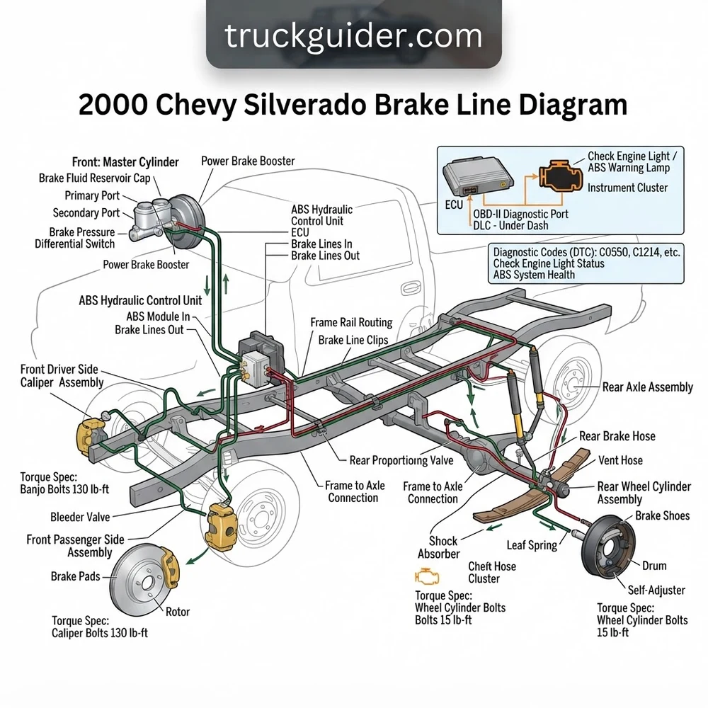
2000 Chevy Silverado Brake Line Diagram and Hydraulic Layout


The hydraulic circuit on the 2000 Chevy Silverado originates at the tandem-reservoir aluminum master cylinder, routes downward to the Kelsey-Hayes 325 Brake Pressure Modulator Valve (BPMV) mounted on the inner driver-side frame rail, and distributes controlled pressure to all four wheel calipers. Understanding this routing requires mapping the primary and secondary circuits independently.
The master cylinder utilizes a stepped bore design. The rear reservoir port supplies the secondary circuit (governing the front calipers via the ABS module), while the forward port delivers hydraulic force to the primary circuit (governing the rear calipers). Unlike older GM C/K platforms that routed lines directly across the firewall, the 2000 Silverado directs both primary and secondary feeds straight down into the top port block of the ABS Hydraulic Control Unit (HCU). As shown in the diagram above, this assembly isolates, dumps, and pulses fluid pressure through internally stepped solenoids managed by the Electronic Brake Control Module (EBCM).
From the ABS HCU outlet ports, three independent high-pressure circuits emerge on standard three-channel systems (or four circuits on four-channel StabiliTrak-equipped variations). The front left hard line exits the module and routes along the top flange of the frame channel directly to the driver-side wheel well bracket, terminating at a reinforced rubber flex hose. The front right hard line navigates beneath the engine along the front crossmember—fastened adjacent to engine bracket hardware and clear of rotating accessories—before reaching the passenger-side caliper flex hose.
The single rear circuit feed exits the ABS module via a larger-diameter hard line, traveling down the inner channel of the driver-side frame rail. It navigates a congested corridor between the frame web and the plastic fuel tank shield before reaching a crossmember-mounted bracket directly forward of the rear axle. Here, the line threads into a heavy-duty chassis-to-axle junction flex hose. At the differential housing, this flexible line connects to an integrated brass tee-fitting block, which bifurcates into dedicated left and right steel axle lines that follow the axle tubes to the rear disc calipers.
| Circuit / Component | Port Label / Location | Line OD | Thread Pitch & Flare Geometry |
|---|---|---|---|
| Master Cylinder Primary Feed | Forward Port (Feeds Rear ABS) | 1/4 in. (6.35 mm) | M12 x 1.0 ISO Bubble Flare |
| Master Cylinder Secondary Feed | Rear Port (Feeds Front ABS) | 1/4 in. (6.35 mm) | M11 x 1.5 ISO Bubble Flare |
| ABS HCU Front Left Outlet | BPMV Port “LF” | 3/16 in. (4.75 mm) | M10 x 1.0 ISO Bubble Flare |
| ABS HCU Front Right Outlet | BPMV Port “RF” | 3/16 in. (4.75 mm) | M10 x 1.0 ISO Bubble Flare |
| ABS HCU Rear Intermediate Outlet | BPMV Port “R” (or “LR/RR”) | 1/4 in. (6.35 mm) | M12 x 1.0 ISO Bubble Flare |
| Rear Axle Junction Tee Outlets | Axle Tube Junction Block | 3/16 in. (4.75 mm) | 3/8-24 Inverted Double Flare |
| Front & Rear Caliper Inlets | Caliper Piston Housing | N/A (Flex Hose) | M10 x 1.5 Banjo Bolt with Crush Washers |
When executing an overhaul, mechanics must note that the factory line transitions between metric and imperial standards across different junctions on the truck. The master cylinder and ABS block strictly require metric ISO bubble flares, while the rear axle junction hardware frequently employs SAE 45-degree inverted double flares. Cross-threading or pairing an inverted flare fitting into an ISO bubble seat will cause seal distortion, irreversible thread stripping, and rapid hydraulic failure under high line pressures.
Brake Line Dimensions, Flare Geometries, and Torque Specs



Precision is mandatory when fabricating lines for the 2000 Silverado. The original equipment manufacturer (OEM) configured the brake system with specific line diameters to balance volumetric displacement against pedal travel. The master cylinder primary and secondary feed runs, along with the main rear intermediate run, utilize 1/4-inch outside diameter (OD) tubing. This larger diameter handles the hydraulic volume required to actuate the dual-piston rear calipers without inducing fluid lag. Conversely, the runs extending from the ABS module to the front calipers and from the rear axle tee to the rear hubs utilize 3/16-inch OD tubing to maintain line rigidity, burst-pressure safety margins, and responsive pedal feedback.
Driveline configuration directly impacts routing paths along the lower chassis:
- Two-Wheel Drive (2WD) Models: The front crossover line travels along the upper lip of the lower front suspension crossmember, secured by nylon retention clips. Because the space forward of the engine oil pan is open, routing is direct, allowing straight drops down the steering knuckle assemblies.
- Four-Wheel Drive (4WD) Models: The front differential assembly, front driveshaft, and transfer case obstruct the lower perimeter of the engine bay. The front right brake line routes high along the upper boxed frame crossmember, using welded standoff tabs to prevent contact with front differential mounts and steering linkages. If lines are positioned improperly, suspension articulation can pinch the tube against the front axle carrier, causing immediate flow restriction.
According to OEM service specifications, all M10 and M12 tube nuts installed into the aluminum ABS BPMV module require a final torque spec of 19 lb-ft (26 Nm). Master cylinder flare tube nuts must be tightened to 18 lb-ft (24 Nm). Banjo bolts securing the flexible brake hoses to the front and rear calipers require a strict torque spec of 30 lb-ft (40 Nm) to achieve an airtight seal on the annealed copper crush washers. Bleeder screws require 106 lb-in (12 Nm).
| Fitting Location | Thread Dimension | Wrench Size | Sealing Mechanism | Torque Target |
|---|---|---|---|---|
| ABS Inlet/Outlet (M10) | M10 x 1.0 | 11 mm or 12 mm | ISO Bubble Flare Face | 19 lb-ft (26 Nm) |
| ABS Inlet/Outlet (M12) | M12 x 1.0 | 13 mm | ISO Bubble Flare Face | 19 lb-ft (26 Nm) |
| ABS Inlet (Secondary M11) | M11 x 1.5 | 12 mm | ISO Bubble Flare Face | 19 lb-ft (26 Nm) |
| Rear Axle Junction Nut | 3/8-24 | 3/8 in. | 45-Degree Inverted Cone | 14 lb-ft (19 Nm) |
| Caliper Banjo Bolts | M10 x 1.5 | 11 mm | Dual Copper Washers | 30 lb-ft (40 Nm) |
Failing to verify flare seat profiles can lead to line failure. In an ISO bubble flare (metric), the sealing surface is the bulbous outer shoulder of the flare compressing against the flat bottom of the internal port. In an SAE inverted double flare, the sealing surface is the internal 45-degree angled cone. Never use standard non-automotive compression fittings on a GMT800 vehicle; hydraulic pressures exceed 1,800 PSI under emergency stopping conditions, which will push a compression joint apart.
GMT800 Brake Line Corrosion Points and Physical Failure Symptoms


The 2000 model year Silverado sits squarely in the generation of trucks notorious for severe corrosion failures. The OEM brake lines were manufactured from copper-brazed, low-carbon steel wrapped in a thin zinc-terne or polyvinyl fluoride (PVF) coating. Over time, road salt, moisture, and fine road debris penetrate this barrier, oxidizing the steel underneath while the outer jacket conceals the deterioration. Technicians inspecting a 2000 Silverado brake line diagram should focus on several known failure points:
- The Driver-Side Intermediate Line Behind the Fuel Tank: This is the most dangerous failure point on the GMT800 platform. The 1/4-inch intermediate line travels along the inside of the frame rail directly outboard of the 26- or 34-gallon fuel tank. Road debris slung by the front tires collects in the 1/2-inch clearance gap between the plastic tank shell and the frame rail. Moisture cannot evaporate from this area, leaving the steel tube sitting in corrosive grit until the line perforates.
- The Frame-Mounted ABS BPMV Module Bracket: The Kelsey-Hayes ABS module sits under the driver-side cab floor, exposed to wheel spray. Salt encrusts the five top-facing ports. Rust blooms around the fitting hex heads, fusing the steel tube nut to the hydraulic line. When line flex occurs during chassis twisting, the brittle steel tube fractures immediately above the fitting.
- The Crossmember Front Crossover Run: This line drops under the engine oil pan. Oil seepage from an oil pressure sensor or timing chain cover seal can trap sand and road salt against the line, holding moisture against the tubing and accelerating corrosion.
- Rear Axle Housing Tubes: The lines traversing the axle tubes are exposed to flying gravel thrown by the rear tires. The protective coating chips away, leading to pinhole blowouts directly behind the differential pumpkin brackets.
A pinhole leak in a GMT800 brake line rarely announces itself under light pedal pressure. It typically ruptures during rapid, panic-stop threshold braking when internal pressures exceed 1,200 PSI. If your brake pedal drops through initial resistance straight to the floorboards, pull over immediately. The secondary master cylinder circuit will only provide minimal front braking force with extended pedal travel.
Physical symptoms indicating active line degradation include a progressive softening of the pedal feel, damp stains on the inner web of the driver-side frame rail, and fluid drips dripping off the bottom of the fuel tank skid plate. If the fluid level drops below the minimum threshold in either reservoir chamber, the dashboard red brake warning light will illuminate immediately via the differential pressure switch located in the master cylinder casting.
Diagnosing Hydraulic Pressure Loss and Check Engine Light Warnings
Accurately troubleshooting hydraulic failure on a 2000 Silverado requires differentiating between mechanical seal bypass, internal ABS leakage, and external pinhole ruptures. Follow this systematic diagnostic protocol to locate failures safely:
- Perform a Static Level and Master Cylinder Inspection: Park the truck on a level surface. Wipe the master cylinder reservoir cap clean and inspect both fluid chambers. If the rear chamber is empty while the forward chamber remains full, the rupture is located along the rear intermediate line or rear axle tubes. If the front chamber is depleted, the leak is located on the master cylinder feed lines, the ABS module, or the front caliper crossover lines.
- Execute an Engine-Off Hydrostatic Pressure Test: Pump the brake pedal 5 to 7 times with the ignition off to deplete the vacuum reserve within the brake booster. Once the pedal becomes firm, apply continuous, heavy foot pressure (approximately 70 lbs) for 45 seconds. If the pedal slowly sinks toward the floor mat with no external fluid visible on the ground, the internal primary piston seal within the master cylinder is bypassing fluid internally. If the pedal drops rapidly accompanied by the sound of escaping fluid or an audible hiss, an external line blowout has occurred.
- Isolate Frame Rail Runs and the ABS Module: Raise the vehicle safely on jack stands or a lift. Using a high-output inspection light, trace the hard lines from the master cylinder downward. Check the Kelsey-Hayes ABS module fittings for dampness or weeping. Use a brass inspection probe to scrape heavy road grime away from the brake lines tucked along the driver-side frame rail directly adjacent to the transmission crossmember and fuel tank straps. Look for damp black stains along the frame channel web.
- Check Caliper Connections and Axle Junctions: Inspect the rear axle junction flex hose for dry rot, swelling, or cracking. Examine where the flexible lines join the axle tubes. Verify that the copper washers on the front and rear caliper banjo fittings are dry. Ensure that weeping has not occurred near engine components; while a loose radiator petcock might affect coolant flow pathways, clear or amber brake fluid pooled on chassis rails indicates hydraulic failure.
- Scan the EBCM and ECU for Diagnostic Fault Codes: Connect a professional diagnostic scanner to the under-dash diagnostic link connector. While hydraulic line leaks will not trigger an engine fault code or directly activate the check engine light, line failures that alter wheel-speed deceleration ratios trigger ABS diagnostic trouble codes (DTCs). Scan the EBCM for fault codes such as C0265 (electronic relay circuit malfunction), C0221 (right front wheel speed sensor circuit open), or C0281 (brake switch circuit malfunction). These trouble codes help isolate whether an electrical communication failure is mimicking a hydraulic malfunction.
2000 Chevy Silverado Brake Line Replacement and OBD-II Bleeding
Restoring the brake plumbing on a 2000 Silverado requires selecting proper materials and applying correct bleeding procedures. Never replace ruptured lines with generic low-carbon steel tubing, as it will corrode again within a few winter seasons. Mechanics have two reliable options: CNC-bent pre-formed 304 stainless steel line kits or seamless Nickel-Copper (NiCopp) alloy tubing.
Stainless steel kits match the exact factory bends shown on the 2000 Chevy Silverado brake line diagram. However, stainless tubing is extremely rigid. Installing a pre-formed one-piece intermediate line requires either unbolting the truck bed and lifting the cab mounts or dropping the fuel tank. Conversely, 90/10 NiCopp tubing (copper-nickel) is fully DOT-approved, rated for over 3,000 PSI burst pressure, and will never rust. Its malleability allows a technician to snake the new 1/4-inch line above the fuel tank without dropping the tank assembly, shaping the bends by hand along the factory retention clips.
When running lines along the engine bay or near the transmission crossmember, ensure lines maintain a minimum 2-inch clearance from exhaust headers and hot transmission cooling conduits. While unrelated systems like the powertrain ECU or front timing chain cover seals operate in high-heat zones, brake fluid is susceptible to thermal vapor lock if routed improperly near exhaust components.
Once all lines are installed and torqued to specification, you must follow the correct fluid-bleed order. The standard mechanical bleeding sequence for the GMT800 platform begins at the wheel furthest from the master cylinder: Right Rear, Left Rear, Right Front, and Left Front.
If air has entered the ABS module—which always occurs when replacing master cylinder feed lines or the main intermediate line—traditional gravity or manual two-person pedal bleeding will not produce a firm pedal. Air pockets become trapped inside the Kelsey-Hayes 325 accumulator cylinders and dump valve pockets. You must connect a bi-directional OBD-II scan tool to the truck’s diagnostic port to perform an Automated ABS Bleed.
The scan tool commands the ABS module to run its internal 12-volt return pump motor and cycle the isolation and dump solenoids in rapid succession. This process drives trapped air bubbles out of the internal BPMV valves into the primary brake lines. After the automated cycle completes, perform a manual pedal bleed at all four calipers using fresh DOT 3 brake fluid. Continue this process until the fluid runs clean and bubble-free, and finish by checking related underbody components, such as your caliper slide pin torque specifications, before returning the truck to service.
2000 Chevy Silverado Brake Line Diagram FAQ and Diagnostic Codes
What are the exact brake line tubing sizes and flare types on a 2000 Silverado 1500?
The 2000 Silverado uses two distinct tubing sizes and flare types. The master cylinder primary line (feeding the rear brakes) and secondary line (feeding the front brakes) are both 1/4-inch OD lines using metric ISO bubble flares (M12x1.0 and M11x1.5, respectively). The single intermediate line running to the rear is also 1/4-inch with an M12x1.0 bubble flare at the ABS module. The lines leading to each front wheel, as well as the lines running across the rear axle tubes, are 3/16-inch OD lines. The front lines terminate in M10x1.0 ISO bubble flares, while the rear axle junction block uses standard SAE 3/8-24 45-degree inverted double flare nuts.
Can you bleed the 2000 Silverado ABS system without an OBD-II scan tool?
If air has migrated into the internal valve bores of the Kelsey-Hayes ABS module, you cannot bleed the system using only the brake pedal. While manual bleeding will clear the hard lines leading to the calipers, the pedal will remain soft and spongy because air pockets compress within the ABS valve bodies. Purging these internal chambers requires a bi-directional OBD-II scan tool capable of commanding the Automated ABS Bleed function. In emergency roadside situations, some technicians cycle the valves by driving on a loose gravel surface and triggering an ABS stop, but this is an unreliable substitute for an electronic scan tool bleed.
Why does the rear brake line rupture primarily behind the gas tank on GMT800 trucks?
The rear intermediate hard line corrodes behind the fuel tank due to a localized design vulnerability on the GMT800 chassis. The line is routed along the inside web of the driver-side frame rail with less than an inch of clearance from the large plastic fuel tank. The front tires kick up water, gravel, and road brine, which collects between the fuel tank and the frame rail. Because this area receives zero airflow or water rinse during standard vehicle washing, road salt remains trapped directly against the steel tubing, accelerating severe galvanic corrosion.
Does a leaking brake line trigger a check engine light or store a diagnostic code?
A leaking brake line will illuminate the red instrument cluster BRAKE warning light via the mechanical differential pressure switch in the master cylinder, but it will not directly illuminate the amber check engine light. The powertrain ECU monitors emissions and engine systems—such as verifying fuel trim, oxygen sensor voltages, or baseline engine oil pressure readings. However, if fluid loss causes a wheel to lock up unexpectedly under braking, the Electronic Brake Control Module (EBCM) may detect an erratic wheel-speed signal and set chassis diagnostic codes (such as C0035 for the left front or C0040 for the right front wheel-speed circuit).
What type and volume of brake fluid is required for a complete system dry-fill?
The factory hydraulic system on a 2000 Chevy Silverado 1500/2500 requires standard DOT 3 glycol-based hydraulic brake fluid, conforming to GM Specification 9985034. When replacing all lines and running an automated ABS purge sequence, approximately two to three 32-ounce (1-quart) containers are required to flush the old fluid and purge air pockets completely. While DOT 4 fluid can be used due to its higher boiling point, never use silicone-based DOT 5 fluid, as it is incompatible with the seals in the Kelsey-Hayes ABS unit and will cause internal seal failure.
Step-by-Step Guide to Understanding the 2000 Chevy Silverado Brake Line Diagram
Identify – Map the master cylinder output ports and compare your line sizes (1/4-inch rear feed vs 3/16-inch front lines) using the schematic.
Locate – Find the ABS module bracket along the inner driver-side frame rail and identify the input and output port stamping markings.
Reference – Trace the schematic routing paths along the frame clips, noting locations where protective spiral wrap shields lines from cab contact.
Connect/Route – Route replacement lines starting from the ABS block outward, threading fittings by hand before tightening to the specified torque spec.
Verify – Connect an OBD-II scanner to monitor the brake ECU, cycle the ABS solenoids to purge air pockets, and inspect all joints under pressure.
Troubleshoot – If pedal travel remains soft or a diagnostic code triggers the check engine light, recheck fittings for seepage and repeat automated bleeding.