2001 Toyota Tacoma Front Suspension Diagram: Repair Guide (2026)

The 2001 Toyota Tacoma front suspension features a double-wishbone independent layout. Key components include upper and lower control arms, coilover shock assemblies, stabilizer sway bar, and rack-and-pinion steering tie rods. Lower ball joint mounting bolts require a critical torque spec of 59 lb-ft with red Loctite to prevent catastrophic detachment.
📌 Key Takeaways
- Lower ball joint (LBJ) flanged bolts require a strict torque spec of 59 lb-ft and high-strength threadlocker.
- 4WD and PreRunner models utilize double-wishbone setups distinct from base 5-lug coil-spring configurations.
- Worn wheel speed ABS sensors integrated at the spindle can trigger a check engine light or ABS diagnostic code.
- Catastrophic lower ball joint failure is the most common safety defect on first-generation Tacomas.
- Replace struts and control arms at home with a press; seek professional alignment immediately afterward.
The 2001 Toyota Tacoma marks a pivotal production phase within the first-generation (1995.5–2004) platform, featuring updated front-end styling, refined steering architecture, and advanced vehicle stability options. Servicing this platform requires a thorough mechanical understanding of its independent front suspension (IFS). Whether you are troubleshooting high-speed steering oscillations, planning a suspension overhaul, or rebuilding structural links, consulting an accurate 2001 Toyota Tacoma front suspension diagram is vital for maintaining vehicle safety and factory alignment specifications. This technical guide delivers an exhaustive breakdown of the front suspension geometry, fastener torque values, component failure profiles, and diagnostic methodologies for professional technicians and advanced DIYers.
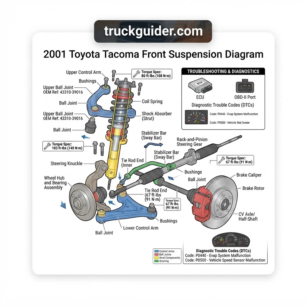
Exploded mechanical schematic detailing the 4WD/PreRunner double-wishbone layout, including lower control arm (LCA) cam bolts, tension-loaded lower ball joint (LBJ), upper control arm (UCA), coilover strut assembly, tie rod ends, and wheel hub assembly.
2001 Toyota Tacoma Front Suspension Diagram: Key Components Labeled

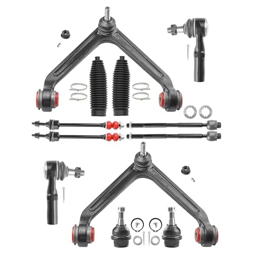


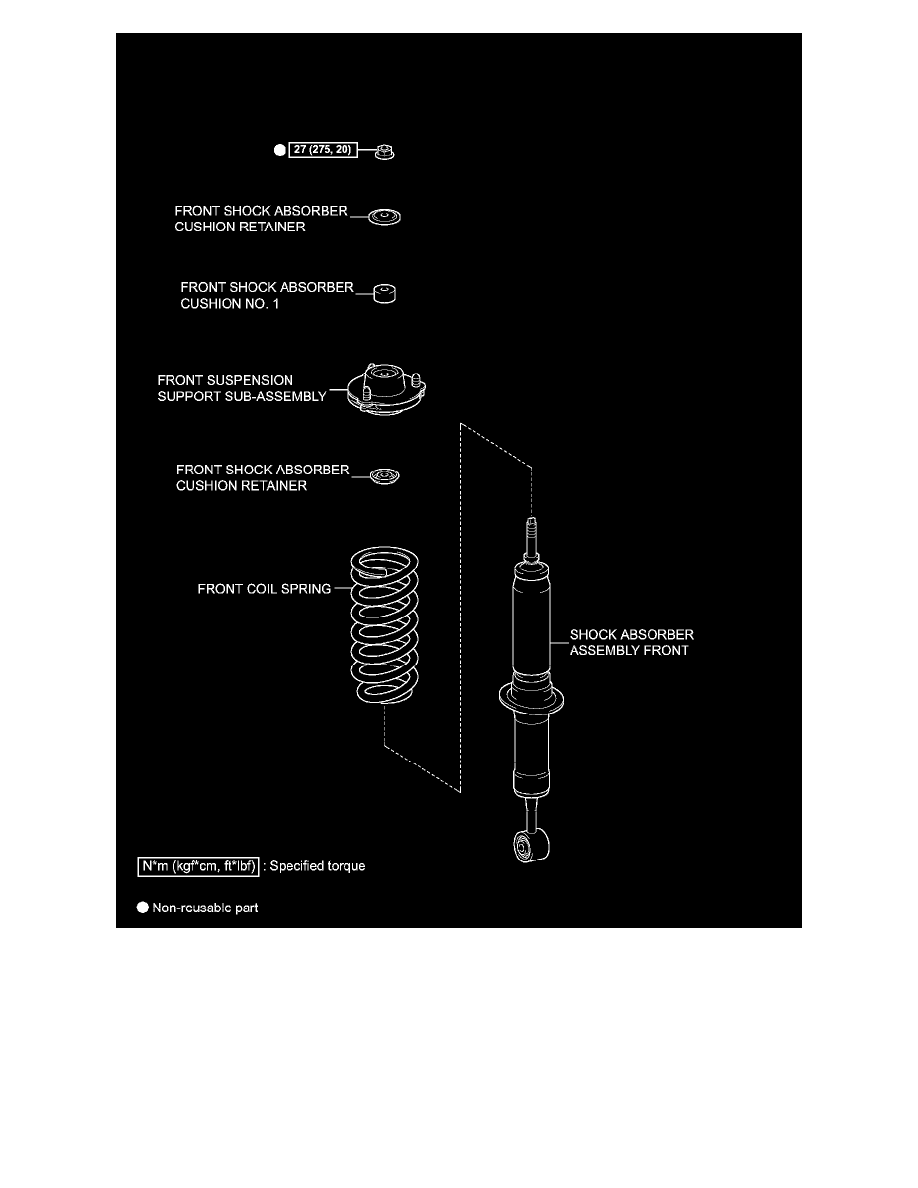
The front suspension architecture of the 2001 Toyota Tacoma utilizes an independent double-wishbone configuration on 4WD and PreRunner (2WD 6-lug) models, whereas base 2WD models use a 5-lug, front-steer configuration. The following breakdown concentrates on the heavy-duty 6-lug chassis shared across the PreRunner and 4WD trims, which accounts for the vast majority of off-road and service-related inquiries.
Lower Control Arm (LCA) and Pivot Assembly

As shown in the diagram above, the Lower Control Arm (LCA) is a high-strength stamped and welded steel assembly that bears the structural and dynamic load of the front corner. The LCA attaches to the front crossmember via two parallel horizontal frame pockets. Inside these frame mounts are bonded natural rubber bushings secured by eccentric alignment cam bolts. These cam bolts (OEM part reference series 48409-35050 / 48452-35020) adjust independent camber and caster. The LCA features a central clevis mount designed to accept the lower eyelet bushing of the coilover shock assembly, a mounting tab for the sway bar end link, and a heavy-duty four-bolt pad at its outboard extremity to seat the lower ball joint cradle.
Upper Control Arm (UCA) and Frame Axis
The Upper Control Arm (UCA) operates as the stabilizing upper link of the double-wishbone geometry, controlling dynamic camber change during suspension compression and rebound. The UCA is forged from tubular steel and pivots on a single, long M14 through-bolt that runs longitudinally through the inner fender apron and two press-fit rubber bushings. At the outboard apex, the UCA houses a press-fit upper ball joint (UBJ) featuring a downward-pointing, tapered stud. This stud inserts into the top casting eye of the steering knuckle, secured via a castellated nut and cotter pin. Unlike the lower joint, the UBJ operates predominantly under follower (stabilizing) loads rather than direct suspension tension.
Steering Knuckle (Spindle) and Wheel Hub Geometry
The steering knuckle is a massive nodular cast-iron component serving as the structural hinge between the upper and lower control arms. It features a bored center section designed to house the front wheel bearing (Koyo OEM standard or equivalent press-fit cartridge). In four-wheel-drive configurations, the center bore accommodates the splined drive axle (CV shaft). The knuckle features forward-facing mounting ears for the dual-piston or four-piston hydraulic brake calipers, an integrated rear-facing steering arm that interfaces with the outer tie rod end, and a machined port for the wheel speed sensor. This inductive sensor sends rotational frequency signals directly to the ABS/VSC skid control ECU, which flags a diagnostic code if air gaps fluctuate due to worn wheel bearings or bent spindle mounts.
For technicians cross-referencing factory service manuals: The 2001 Tacoma 6-lug IFS differs substantially from the 5-lug base model. The 5-lug utilizes a coil spring placed directly between the frame and lower control arm with a standalone shock absorber, whereas the 6-lug uses a true coil-over-strut architecture. Never interchange knuckle, ball joint, or control arm components between 5-lug and 6-lug frames.
Coilover Assembly (Coil Spring and Shock Absorber)
The primary springing and damping element is an integrated coil-over-shock unit. It comprises a progressive or linear steel coil spring encapsulated around a gas-pressurized, twin-tube or monotube hydraulic damper. The top of the assembly utilizes a stamped steel mounting plate (strut hat) with three welded M10x1.25 studs that penetrate the upper shock tower frame bracket. The internal damper shaft passes through a central elastomeric isolator bushing, secured with a self-locking nylon M12 center nut. The base of the shock cylinder ends in a reinforced eyelet with a vulcanized rubber bushing, pinned into the lower control arm channel by an M16 grade 10.9 high-tensile bolt.
2001 Toyota Tacoma Front Suspension Diagram Fastener Torque Spec Table


Adhering to factory-specified fastener torque values is imperative when assembling IFS components. Applying incorrect clamping force to tapered ball joints or eccentric cam bolts leads to dynamic fatigue failure, steering wandering, or stripped mounting ears. The table below outlines the factory-mandated torque spec values according to Toyota OEM workshop manuals.
| Fastener / Joint Description | Hardware Size & Pitch | Torque Spec (ft-lb) | Torque Spec (N·m) |
|---|---|---|---|
| Lower Ball Joint (LBJ) Attachment Bolts (4 per side) | M10 x 1.25 (Flanged Grade 10.9) | 59 ft-lb | 80 N·m |
| Lower Ball Joint Main Castle Nut (to Knuckle) | M16 x 1.5 Castle Nut | 103 ft-lb | 140 N·m |
| Upper Ball Joint (UBJ) Castle Nut | M14 x 1.5 Castle Nut | 80 ft-lb | 108 N·m |
| Eccentric Alignment Cam Bolts (LCA Pivot) | M16 x 1.5 Eccentric Nut | 96 ft-lb | 130 N·m |
| Upper Control Arm (UCA) Frame Through-Bolt | M14 Long Pivot Bolt | 87 ft-lb | 118 N·m |
| Outer Tie Rod End Castle Nut | M12 x 1.25 Castle Nut | 67 ft-lb | 91 N·m |
| Inner Tie Rod to Steering Rack (Rack End) | M20 Threaded Joint | 70 ft-lb | 95 N·m |
| Tie Rod Jam Nut (Outer to Inner) | M16 Jam Nut | 42 ft-lb | 56 N·m |
| Coilover Shock Lower Mount Bolt (LCA) | M16 x 1.5 Through-Bolt | 100 ft-lb | 135 N·m |
| Coilover Shock Top Hat Upper Nuts (3x per side) | M10 x 1.25 Flange Nut | 47 ft-lb | 64 N·m |
| Sway Bar End Link Nut (Top and Bottom) | M10 x 1.25 Metric Nut | 22 ft-lb | 29 N·m |
Whenever replacing the four lower ball joint M10x1.25 attachment flange bolts, always discard the used fasteners. Install genuine Toyota OEM bolts (Part # 90119-10610 or 90105-10406) coated with high-strength blue or red thread-locking compound. Torque in a crisscross sequence to exactly 59 ft-lb (80 N·m) to prevent shear-load unseating.
Common 2001 Tacoma Front Suspension Diagram Failure Points and Wear Symptoms

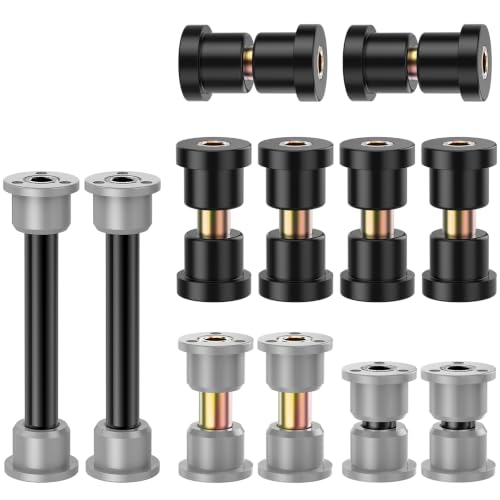


First-generation Tacomas are renowned for mechanical durability, matching the legendary endurance of their internal combustion components—from the robust timing chain on the 2.7L 3RZ-FE to the balanced oil pressure and coolant flow circuits of the 3.4L 5VZ-FE. However, the 1st Gen IFS layout possesses critical failure points that must be actively monitored to prevent catastrophic front-end breakdown.
The 2001 Toyota Tacoma front suspension diagram shows an underslung, tension-loaded lower ball joint. Vehicle weight and dynamic spring rebound continually pull the ball stud out of its socket casing. If internal clearance exceeds service limits, the ball stud tears out completely, severing steering control, snapping the front brake line, destroying the CV axle, and causing the front fender to collapse onto the pavement.
- Catastrophic Lower Ball Joint (LBJ) Separation: Unlike newer chassis designs where the vehicle mass rests on top of the ball stud (compression loading), the 2001 Tacoma places the LBJ in tension. Symptoms of advanced wear include a low-speed clunking noise when navigating driveway aprons, wandering on uneven asphalt, and metallic squeaking during slow-speed steering sweeps. Severe joint degradation will not always trigger a dashboard warning, although wheel displacement during joint separation can sever ABS speed wiring harnesses, triggering an immediate ABS fault or check engine light on systems monitored by the vehicle skid control ECU.
- Frozen Eccentric Alignment Cam Bolts: Road debris, water ingress, and galvanic corrosion weld the steel shank of the M16 eccentric cam bolts to the inner steel sleeve of the lower control arm rubber bushings. When frozen, professional alignment shops cannot adjust caster or camber angles. Symptoms include persistent pulling to one side, rapid inner shoulder tire wear, and an off-center steering wheel. Freeing them often requires reciprocating saws or oxy-acetylene torch work to cut through the hardened sleeve, necessitating full LCA bushing replacement.
- Sway Bar (Stabilizer Bar) Bushing and Link Wear: The 27mm front stabilizer bar uses frame-mounted D-bushings and vertical ball-jointed or grommet-style end links connected to the lower control arm. When the rubber degrades or the link micro-joints lose grease, drivers will experience a sharp metallic popping or knocking sound felt through the floorboards whenever the suspension articulates over diagonal speed bumps or off-road ruts.
- Steering Rack Guide Bushing and Tie Rod Play: The hydraulic power steering rack uses an internal guide block to hold the steering rack bar against the pinion gear. Over time, internal guide clearance loosens, manifesting as front-end vibration, steering wander, and excessive play at highway speeds. This instability can be mistakenly attributed to unbalanced wheels or drivetrain vibrations, such as loose engine mounts or timing chain harmonic resonance.
- Upper Control Arm Bushing Dry-Rot and Separation: The rubber bushings pressed into the UCA frame mount oxidize and crack over decades of operational cycles. This introduces radial slop into the upper suspension hinge, causing dynamic caster migration under hard braking. The driver will observe a heavy nose-dive combined with erratic pulling to the left or right, independent of brake caliper hydraulic pressure balance.
Diagnosing 2001 Tacoma Front Suspension Play and Chassis Diagnostic Code Triggers

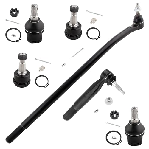


Diagnosing play within the 2001 Tacoma double-wishbone front end requires a structured, mechanical procedure. Due to the tension-loaded configuration of the coil-over-strut, standard suspension checking techniques—such as lifting the vehicle by the chassis frame rails—will leave the suspension at full droop. In full droop, the coil spring wedges the lower ball joint into its socket under extreme downward tension, masking ball joint axial clearance and loose internal tolerances.
- Properly Lift and Unload the Suspension Assembly: Position a heavy-duty hydraulic floor jack directly beneath the lower control arm (LCA) spring seat pad on the side you are inspecting. Raise the wheel approximately three inches off the floor and place a secondary jack stand under the frame rail for safety. Lifting under the LCA compresses the coilover spring slightly, keeping the control arm at ride height and fully unloading the internal mechanical tension across the lower ball joint.
- Measure Lower Ball Joint (LBJ) Axial and Radial Play: Mount a magnetic base dial indicator to the lower control arm and place the gauge plunger tip vertically against the bottom flat of the steering knuckle housing. Insert a 36-inch pry bar between the tire tread and the ground, or directly between the LCA casting and the knuckle base. Gently pry upward while observing the gauge face.
OEM Specification: According to Toyota factory tolerances, maximum allowable vertical (axial) play is 0.5 mm (0.020 in). Any perceptible axial movement registered on the dial indicator requires immediate replacement of both left and right lower ball joint assemblies. - Inspect Upper Ball Joint (UBJ) and Spindle Attachment: With the wheel still suspended, grab the tire at the absolute 12 o’clock and 6 o’clock positions. Push inward firmly at the top of the tire while pulling outward at the bottom, then reverse the force. Look and feel for lateral play at the upper knuckle neck where the UBJ tapered stud connects. If movement or a distinct clicking sound is observed, verify whether the motion originates from the UBJ ball stud, the wheel bearing assembly, or degraded UCA frame pivot bushings. Use a pry bar between the UCA and the coil spring frame bracket to isolate bushing deflection.
- Evaluate Steering Linkage and Rack Slack: Grasp the tire at the 9 o’clock and 3 o’clock positions and wiggle it back and forth with short, deliberate lateral pulses. Have an assistant monitor the steering linkage.
- Movement isolated to the outer tie rod end ball joint indicates a worn tie rod end requiring replacement.
- Movement traveling into the protective rubber steering bellows indicates internal wear within the inner tie rod (rack end) ball socket.
- Vertical movement of the entire steering rack shaft through the passenger-side guide sleeve indicates failed rack mounting bushings or an excessively worn internal rack guide brass slipper.
- Scan and Clear Chassis Diagnostic Codes via OBD-II: If suspension or steering rack play has caused violent vibrations, inspect the shielded wiring harness leading to the ABS wheel speed sensor on the steering knuckle. Excessive wheel bearing play or joint runout can cause the reluctor ring teeth to contact the sensor tip or damage the internal sensor coil. Connect an OBD-II diagnostic tool to the DLC3 port located beneath the lower driver-side instrument panel. Read all stored chassis diagnostic trouble codes (DTCs). Fault codes such as ABS DTC 31, 32, 33, or 34 indicate front wheel speed sensor signal interruptions. Rectify physical suspension play, verify sensor harness continuity, and clear the fault codes from the ECU to ensure proper traction control, ABS, and stability control operation.
- Perform Final Inspection of Bushings and Fasteners: Lower the truck back onto its tires so the suspension settles completely at curb weight. Visually inspect the lower control arm eccentric alignment cam plates to confirm the index marks align with frame alignment notches. Ensure that sway bar end link bushings are not compressed past their outer washers, and confirm that all cotter pins are correctly installed through the castellated nuts on the lower ball joint, upper ball joint, and outer tie rod ends.
Frequently Asked Questions: 2001 Toyota Tacoma Front Suspension Diagram
Why are 2001 Toyota Tacoma lower ball joints prone to sudden failure?
The 2001 Tacoma uses an “underslung” lower ball joint loaded in tension rather than compression. Because the coilover mounts directly to the lower control arm and the ball joint mounts underneath the steering knuckle, vehicle weight and road impacts continually try to pull the ball stud out of the housing cup. When the internal bearing race wears out, the ball separates cleanly from the housing, detaching the spindle from the control arm. In contrast, compression-loaded designs press the ball tighter into the cup under load, eliminating this mode of failure.
What indicates that front-end eccentric alignment cam bolts are seized?
When an alignment technician attempts to turn the M16 eccentric cam bolt adjusters and observes the inner rubber bushing twisting or stretching rather than the bolt sleeve rotating smoothly inside the bushing, the cam bolt is seized. Galvanic corrosion between the steel eccentric sleeve and the lower control arm bushing tube locks them together. If forced with a breaker bar or impact gun, the eccentric alignment tabs on the frame will shear off, requiring replacement of the lower control arm, bushings, and cam hardware.
Can a worn front wheel bearing or loose suspension joint trigger an ABS check engine light?
Yes. The wheel speed sensor is mounted directly into the top of the steering knuckle, positioned fractions of a millimeter away from the toothed reluctor ring pressed onto the wheel hub. Severe wheel bearing play, excessive spindle deflection, or loose ball joints cause dynamic air gap fluctuations. This distorts the sinusoidal voltage signal sent to the ABS/skid control ECU. The ECU interprets this erratic signal as an implausible wheel speed variation, setting an ABS fault code and illuminating the ABS warning light, which on certain California-emissions models can also trigger an associated check engine light.
Should I torque the lower control arm cam bolts while the truck is elevated on a lift?
No. Never fully torque the lower control arm pivot cam bolts or the upper control arm long through-bolt while the suspension is hanging at full rebound droop. The internal rubber bushings must be torqued only when the truck is resting at normal ride height under curb weight. Torquing suspension pivot bushings while elevated pre-twists the rubber, causing immediate torsional stress and premature bushing tear out within a few thousand miles.
What is the replacement interval for lower ball joints on a 2001 Tacoma?
Due to the tension-loaded design risks, mechanical consensus dictates replacing 2001 Tacoma lower ball joints every 100,000 miles for standard highway driving, and every 60,000 to 75,000 miles for vehicles operating with suspension lift kits, oversized off-road tires, or under harsh trail conditions. Always install genuine OEM Toyota ball joint assemblies and factory Grade 10.9 attachment bolts treated with threadlocker to ensure maximum operational safety.
Step-by-Step Guide to Understanding the 2001 Toyota Tacoma Front Suspension Diagram
Identify – Inspect the diagram to identify whether your truck has the 6-lug (4WD/PreRunner) or 5-lug front suspension setup.
Locate – Locate the lower ball joint, control arm bushings, sway bar end links, and steering knuckle mounting points.
Reference – Reference the schematic for fastener grades and the exact torque spec required for each suspension fastener.
Connect/Route – Route ABS wiring harnesses carefully along the spindle bracket to prevent tension damage that trips an ECU check engine light.
Verify – Verify all fasteners meet factory torque specs, check for play using a pry bar, and scan via OBD-II if warning lights appear.
Troubleshoot – Troubleshoot persistent steering wander or uneven tire wear by checking alignment cam bolt positioning against the diagram geometry.