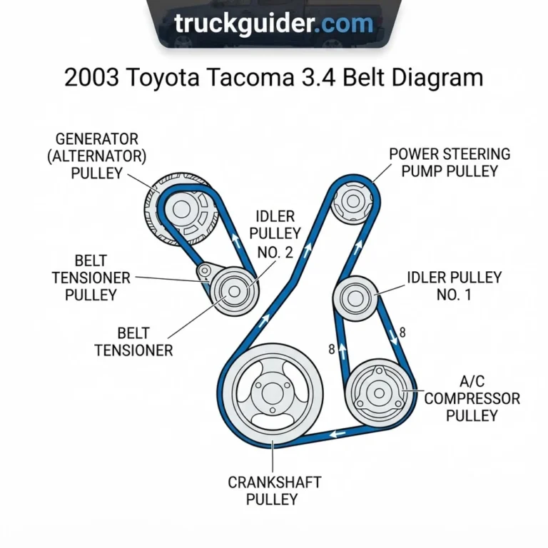
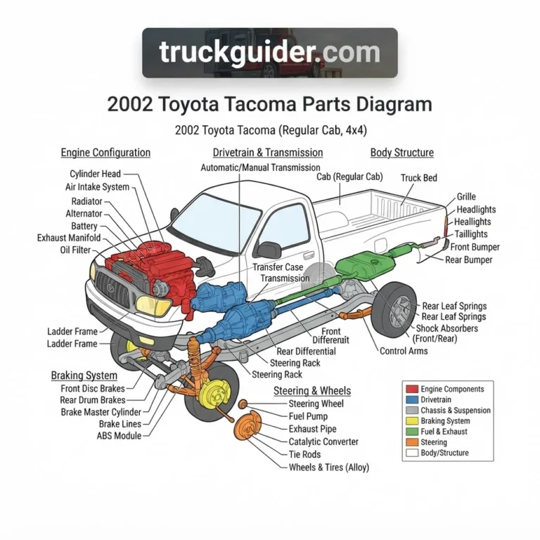
2004 Toyota Tacoma Parts Diagram: Component Breakdown (2026)

The 2004 Toyota Tacoma parts diagram illustrates sub-assemblies for the first-generation platform, mapping the 2.7L 3RZ-FE or 3.4L 5VZ-FE engine layout, W59/R150F transmissions, and double-wishbone front suspension. It provides OEM reference numbers, structural frame mounting points, and bolt torques, such as lower ball joint bolts torqued to 59 lb-ft.
📌 Key Takeaways
- Lower ball joint mounting bolts require 59 lb-ft of torque with blue Loctite to prevent catastrophic separation.
- Covers 1st-generation final year revisions, differentiating 2.4L 2RZ-FE, 2.7L 3RZ-FE, and 3.4L 5VZ-FE engine bay configurations.
- Rear leaf spring U-bolts must be torqued in a cross pattern to 90 lb-ft when servicing rear axle assemblies.
- Common structural failure points include rear frame rail rust perforation and cracked front coil spring perches.
- Direct mechanical bolt-ons are straightforward DIY; complex differential rebuilding or frame plating requires professional alignment gear.
Navigating the factory parts layout of the final model year of the first-generation Tacoma demands an understanding of Toyota’s engineering taxonomy. The 2004 model year marks the culmination and absolute conclusion of the N140, N150, N160, and N170 chassis platform (1995.5–2004). Sourcing accurate components for complete frame-off restorations, suspension rebuilds, or powertrain overhauls requires referencing an authentic 2004 Toyota Tacoma parts diagram derived directly from the original equipment manufacturer (OEM) technical catalog. This guide examines the system schematics, exploded views, component numbering architecture, and subsystem configurations unique to the 2004 model year, giving certified mechanics and master technicians the blueprint needed to isolate correct assemblies without fitment errors.
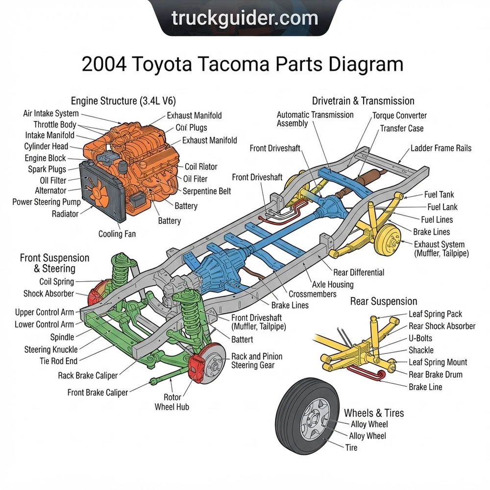
2004 Toyota Tacoma Parts Diagram Layout and Architecture



The structural organization of a 2004 Toyota Tacoma parts diagram adheres strictly to the database architecture established by the Toyota Electronic Parts Catalog (EPC). Unlike generic retail diagrams that group parts by informal maintenance tasks, the OEM catalog categorizes vehicle components into four primary operational sections: Tool/Engine/Fuel, Power Train/Chassis, Body, and Electrical. Every individual assembly on the truck is nested hierarchically within these high-level groups, flowing from major mechanical casting groups down to captive hardware, O-rings, and sub-assembly spring clips.


As the definitive release of the first-generation Toyota Tacoma (1995.5-2004), the 2004 technical layout incorporates critical micro-revisions implemented toward the end of the production cycle. For powertrain schematics, the catalog branches fundamentally based on engine displacement. Technicians will find distinct engine layout groupings for the 2.4L 2RZ-FE inline-4 (standard on 5-lug two-wheel-drive platforms), the 2.7L 3RZ-FE inline-4 engine (featured on 4WD and PreRunner models), and the venerable 3.4L 5VZ-FE V6 engine. By 2004, the 5VZ-FE schematic reflected late-generation changes, including an electronic throttle body design integrating the Electronic Throttle Control System-intelligent (ETCS-i), which eliminated the traditional mechanical idle air control (IAC) valve sub-assemblies found on earlier models.
A critical operational mistake made by technicians is attempting to cross-reference parts between the 2004 platform and later model years. The 2004 schematics do not cross over to the 2005 model year in any capacity. The 2005 Tacoma initiated the second-generation platform (GRN200/TRN220 series), which underwent an expansive redesign. The 2005 platform introduced entirely new powertrains (the 4.0L 1GR-FE V6 and 2.7L 2TR-FE I4), switched to a wider, fully boxed-to-C-channel composite-bed frame, integrated completely different double-wishbone front geometry with top-mounted ball joint studs, and transitioned to a Controller Area Network (CAN-bus) electrical architecture. Consequently, 2004 chassis blueprints, powertrain diagrams, and electrical schematics remain strictly proprietary to the late first-generation platform.
When accessing the Toyota EPC for a 2004 model, always match the catalog classification to the VIN’s fourth digit (chassis type) and fifth digit (engine model). The 2004 model year features distinct evaporative emission (EVAP) routing blueprints, as the charcoal canister was relocated from the engine bay to above the spare tire carrier, fundamentally changing the fuel line exploded diagrams compared to pre-2001 models.
Core Subsystem Schematics in the 2004 Tacoma Parts Breakdown


To service or rebuild a late first-generation truck correctly, technicians must consult individual subsystem schematics. Each exploded view isolates assemblies down to individual fasteners, mating shims, and sub-assembly rebuild kits. The table below outlines the primary mechanical subsystems documented across official 2004 schematics, detailing callout behaviors, primary sub-components, and critical factory installation specifications.
| Subsystem Schematic | Primary Components Labeled | Typical PNC Callout | Critical Engineering Specs & Notes |
|---|---|---|---|
| Engine Assembly Diagram (3.4L 5VZ-FE V6) | Cylinder block, cylinder heads, crankshaft, timing belt, hydraulic tensioner, camshaft pulleys, water pump, ETCS-i throttle body. | 11401 (Block) 13568 (Belt) 13540 (Tensioner) 16100 (Pump) |
Crankshaft pulley bolt torque: 217 ft-lbs (294 Nm). Timing belt tensioner bolts: 20 ft-lbs (27 Nm). Water pump with gasket: 14 ft-lbs. Camshaft pulley bolt: 72 ft-lbs. |
| Front Suspension & Steering Diagram (6-Lug 4WD/PreRunner) | Upper control arm, lower control arm, steering knuckle, lower ball joint (LBJ) assembly, coil-over shock, steering rack and pinion, outer tie rods. | 48068 (LCA RH) 43330 (LBJ RH) 43340 (LBJ LH) 44250 (Rack Assy) |
Lower ball joint to knuckle: 4 bolts torqued to 59 ft-lbs (80 Nm) with medium/high-strength threadlocker. LBJ castle nut to LCA: 103 ft-lbs (140 Nm). Outer tie rod end castle nut: 67 ft-lbs. |
| Rear Axle & Suspension Diagram | Rear axle housing, differential carrier (8-inch or 8.4-inch), axle shafts, leaf springs, shackle plates, U-bolts, load sensing proportioning valve (LSPV). | 42110 (Axle Housing) 41110 (Diff Carrier) 48210 (Leaf Spring) 47910 (LSPV Valve) |
U-bolt nuts torqued diagonally: 90 ft-lbs (123 Nm). Rear axle bearing retainer nuts: 51 ft-lbs. Third-member differential retaining nuts: 54 ft-lbs. |
| Transmission & Transfer Case Diagram (A340F / VF2A) | Transmission bellhousing, torque converter, valve body, planetary gearsets, 4WD transfer case assembly, actuator motor, drive chain. | 35000 (Trans Assy) 35168 (Pan Gasket) 36100 (T-Case Assy) 36410 (Actuator) |
Transmission pan pan-bolts: 65 in-lbs (7.4 Nm). Bellhousing to 5VZ-FE block bolts: 53 ft-lbs (17mm head) / 29 ft-lbs (14mm head). Drain plug torque: 15 ft-lbs. |
Powertrain Architecture: 3.4L 5VZ-FE vs. 2.7L 3RZ-FE


The engine assembly diagram for the 3.4L 5VZ-FE features a 60-degree V6 iron block with aluminum DOHC heads, operating a four-cam, 24-valve system driven by a single multi-ribbed timing belt. Technicians must note that the timing drive blueprint differs vastly from the 2.7L 3RZ-FE. The 3RZ-FE inline-4 engine schematic relies on a dual-roller timing chain architecture with internal twin balance shafts, hydraulic chain tensioners, and plastic chain guide rails (PNC 13559 and 13561). When viewing the fuel injection system schematic for either engine on a 2004 model, note that the fuel delivery configuration uses returnless rail designs on late configurations, omitting the manifold vacuum-referenced fuel pressure regulator found on the fuel rails of 1995.5-1999 models.


Chassis, Steering Knuckle, and Driveline Subsystems
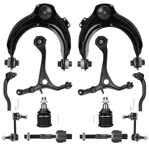
In the front suspension and steering schematic, the 2004 6-lug configuration uses an independent double wishbone layout. The critical mechanical component in this schematic is the lower ball joint (LBJ), which mounts in tension. The ball stud extends upward into the steering knuckle and is secured from underneath via four flanged grade 10.9 bolts (M10 x 1.25 thread pitch). On 4WD models, the front hub schematic illustrates the sealed unit-bearing hub assembly driven by a constant-velocity (CV) half-shaft, retained inside the wheel spindle by a massive 35mm axle spindle nut (PNC 90179-28003) torqued to an OEM specification of 174 ft-lbs (235 Nm).
The transmission and transfer case exploded diagrams depend heavily on trim configuration. While 5-lug manual models utilize the light-duty W59 five-speed transmission, 4WD and PreRunner V6 models utilize either the heavy-duty R150F manual transmission or the A340F (4WD) / A340E (2WD) four-speed electronically controlled automatic. Technicians performing an A340F transmission valve body rebuild must consult the hydraulic plate schematic specifically for the 2003-2004 model years, as the transmission solenoid configuration and valve body casting were modified to accommodate linear throttle pressure solenoids.
Factory torque for the four lower ball joint flange bolts on 2004 6-lug models is exactly 59 ft-lbs (80 Nm). Toyota Technical Service Bulletins specify replacing these bolts with new OEM hardware (Part Number 90119-10933) whenever the lower ball joint assembly is disconnected from the steering knuckle, applying high-strength threadlocker to guarantee structural retention under cyclic suspension loads.
How to Read a 2004 Toyota Tacoma Parts Diagram Step by Step


Reading an authentic Toyota schematic requires translating functional visual callouts into physical parts that can be ordered from a distribution center. Toyota schematics do not place standard part numbers directly onto the mechanical illustration. Instead, they use a structured system to separate functional part identity from specific inventory revisions. Follow this systematic workflow to accurately decode any 2004 Tacoma exploded view.


- Decode the Complete VIN and Frame Model Code: Begin by locating the vehicle identification plate on the driver’s side door jamb or firewall. Extract the complete VIN alongside the specific model designation (e.g., VZN170L-CRMDKAB). The first three letters denote the engine and frame series: “VZN170” indicates a 3.4L 5VZ-FE platform with a 4WD, 6-lug chassis. “RZN161” denotes a 2.7L Xtracab PreRunner. This model code acts as the ultimate filter in the Toyota Electronic Parts Catalog (EPC), pruning non-compatible sub-assemblies out of your search tree.
- Navigate to the Major Group and Subsystem Section: In the catalog index, select the parent group: Tool/Engine/Fuel, Powertrain/Chassis, Body, or Electrical. Open the designated subsystem illustration. For instance, to replace a blown rear differential seal, navigate to Powertrain/Chassis > Group 41-01 (Rear Axle Housing & Differential).
- Trace the Exploded View Stack to Locate the Assembly Callout: In the technical drawing, inspect the component callout lines. Fasteners, spring washers, dynamic seals, and core structural castings are organized in exploded order of assembly. Trace the component to its 5-digit or 6-digit numeric reference flag. This number is the Part Name Code (PNC).
- Identify and Decode the Part Name Code (PNC): The PNC is a standardized functional locator used across all Toyota vehicle platforms. For example, PNC
13568universally indicates “Timing Belt,” and PNC43330indicates “Joint Assembly, Lower Ball, Front RH.” The PNC does not represent an orderable part number; it merely informs the catalog database what functional role the selected part plays in that specific diagram position. - Cross-Reference the PNC to Extract the 10-Digit OEM Part Number: Select the PNC within the catalog software or click its corresponding line item in the reference table. The EPC cross-references the PNC against your previously entered VIN and production date (e.g., 03/2004). The catalog then outputs the unique, orderable 10-digit Toyota Part Number, structured as a 5-digit base number followed by a 5-digit detail/variant code (e.g.,
43330-39585). - Audit Part Number Supersessions and Suffix Variations: Review the catalog results for supersession notices. Frequently, early part numbers are replaced by updated Toyota engineering numbers (e.g.,
13568-69095superseding to the universal service replacement kit13568-YZZ03). Verify color-code suffixes (common on interior trim panels, which append -B0, -E0, or -C0) and right-hand versus left-hand symmetry tags (RH vs. LH).
Never attempt to purchase replacement hardware or structural components using only the 5-digit PNC callout. Supplying a distributor with a PNC instead of the complete 10-digit part number (or 12-digit format with color codes) will result in ordering the wrong component or receiving an invalid catalog lookup error.
Suspension, Frame, and Driveline Configuration Blueprint


Chassis specifications on the 2004 Toyota Tacoma vary significantly based on cab dimensions, payload ratings, drive types, and historical safety actions. Technicians must understand these variations to avoid ordering components designed for a different configuration.
| Platform Configuration | Lug Pattern & Track Width | Front Suspension Architecture | Rear Axle & Differential Spec | Frame Type & Leaf Configuration |
|---|---|---|---|---|
| 2WD Standard / DLX (Base 5-Lug) | 5-lug on 4.5 in (5×114.3mm) Track: 57.1 in |
Coil spring over upper arm, compression-loaded ball joints, sway bar under lower control arm. | 7.5-inch differential, non-locking, standard drum brakes. | Low-slung C-channel frame rails, spring-under-axle (SUA) rear leaf pack. |
| Tacoma PreRunner (2WD Raised Chassis) | 6-lug on 5.5 in (6×139.7mm) Track: 59.8 in |
Identical to 4WD: Coil-over shock mounted to lower control arm, tension-loaded lower ball joints. | 8.0-inch or 8.4-inch (without ABS/TRAC), optional factory electric locking differential (PNC 41110-3D080). | High-clearance boxed/C-channel frame, spring-over-axle (SOA) rear leaf configuration. |
| 4WD (Regular, Xtracab, Double Cab) | 6-lug on 5.5 in (6×139.7mm) Track: 59.8 in |
Coil-over shock on lower control arm, tension-loaded LBJ, dynamic front CV axles with ADD disconnect. | 8.0-inch (with factory e-locker) or 8.4-inch standard differential carrier, optional mechanical LSD. | High-clearance boxed/C-channel frame, spring-over-axle (SOA) rear leaf pack, LSPV brake valve. |
The 5-Lug vs. 6-Lug Chassis Dichotomy
The most common ordering error occurs when confusing 5-lug utility configurations with 6-lug PreRunner/4WD platforms. A 5-lug 2004 Tacoma features an inverted suspension system compared to a 6-lug truck. In the 5-lug parts diagram, the coil spring sits directly on top of the upper control arm, forcing the lower control arm to function solely as an alignment and locating link. Conversely, the 6-lug diagram places the coil-over strut assembly against the lower control arm. This means the lower ball joints, control arms, sway bar links, and steering racks share zero interchangeability between 5-lug and 6-lug 2004 models.
Chassis Replacement Campaigns and Service Assemblies


Due to severe corrosion issues involving the original Dana-supplied frames on first-generation models, Toyota initiated a massive Safety Recall and customer support campaign covering 2004 models. Technicians referencing a first-generation Tacoma frame rust inspection or frame replacement parts diagram should recognize that replacement frames (part numbers within the 51001-XXXXX sequence) were provided with updated electro-deposition coating, redesigned rear leaf spring frame perches, and new brake line routing brackets. When viewing frame service diagrams, verify whether you are working with an original factory-built chassis or an updated replacement frame assembly, as bolt hole threading for the rear brake proportioning valve and fuel tank crossmembers can differ slightly.
Electrical wiring and relay block schematics also vary by drive type. PreRunner and 4WD models equipped with an optional factory rear differential lock incorporate an auxiliary Locking Differential Control ECU (PNC 89533-35070) positioned behind the driver’s side lower kick panel. These models route an isolated 6-wire harness through the floor pan grommet directly to the differential actuator, complete with a specialized 4WD/Diff-Lock dash indicator circuit illustrated in the Group 84-01 switch schematics.


Troubleshooting 2004 Toyota Tacoma Parts Diagram Lookup Errors
Even seasoned parts specialists and technicians run into catalog lookup traps on late first-generation trucks. Below are the most common schematic lookup errors, their root causes, and how to verify part accuracy before ordering.
- Confusing the 2004 Configuration with a 2000 Toyota Tacoma Parts Diagram: The 1995.5-2000 models use older engineering designs that differ significantly from late-production models. A 2000 Tacoma parts diagram features a mechanical throttle cable running to a traditional throttle body with an IAC valve, an engine-bay-mounted charcoal EVAP canister, and a 2-channel or 3-channel ABS system. Searching under a 2000 model year schematic for a 2004 truck will result in ordering incorrect intake components, wrong throttle position sensors (TPS), incompatible cruise control actuators, and completely incorrect fuel tank vapor lines.
- Relying on Aftermarket Repair Manual Schematics (Haynes/Chilton): Commercial third-party manuals consolidate multiple model years (typically 1995–2004) into single, highly generalized exploded views. These universal schematics regularly omit critical revision updates, such as the differential side bearing shim variations, specific rear axle bearing retainer collar orientations, or the anti-lock brake actuator revisions introduced for the 2003-2004 model years. Always verify part fitment using OEM microfiche or electronic catalogs rather than third-party publications.
- Cross-referencing Against the 2005 Toyota Tacoma Parts Diagram: Entering “2005” instead of “2004” when sourcing parts leads to complete order failure. The 2005 model year marked the launch of the second-generation Tacoma. Virtually nothing transfers between the two: control arms, hubs, brake rotors, engines, transmissions, leaf springs, and body hardware are entirely different. Double-check the 10th digit of the truck’s VIN: an “4” indicates a 2004 model, while a “5” denotes the second-generation 2005 platform.
- Ordering by Generic Part Name Code (PNC) Rather than Full 10-Digit Numbers: Entering a 5-digit number like “48131” into an online OEM dealership portal will either yield no results or
48131-AF090for a specific cab, engine, and suspension package rating). - Overlooking California vs. Federal Emissions Schematics: In 2004, exhaust system diagrams are split between Federal (EPA) and California (CARB) emissions configurations. California-spec models use an Air/Fuel (A/F) ratio sensor ahead of the catalytic converter (PNC 89467, Part Number
89467-35011on 5VZ-FE), which utilizes a specialized planar-type sensing element. Federal models use a standard heated oxygen sensor (PNC 89465). The mounting flange stud spacing and wiring harness pinouts do not match. Inspect the under-hood emissions label to verify whether the truck conforms to California or Federal standards before checking the exhaust parts schematic.
Frequently Asked 2004 Toyota Tacoma Parts Diagram Questions
How do I determine if my 2004 Tacoma rear axle schematic requires the 8-inch or 8.4-inch diagram?
Examine the structural design of the rear differential carrier and check the vehicle’s production options. If your 2004 truck is equipped with a factory electric locking rear differential (indicated by the “RR DIFF LOCK” dashboard switch), the axle uses the Toyota 8-inch differential schematic, which features an 8-inch ring gear, a 12-bolt third-member mounting pattern, and an actuator mounting cut-out. If your truck is a 6-lug PreRunner or 4WD without a factory e-locker, it uses the heavy-duty differential schematic known in the industry as the “8.4-inch” (or 8-inch non-drop-out with bearing cap truss). This differential features a 10-bolt mounting pattern and a reinforced bearing cap girdle structure.
Where can I find the electrical wiring & relay block diagram for the 2004 Tacoma fuel pump circuit?
The fuel pump circuit is documented in Group 84-01 (Wiring & Clamp) and the official 2004 Toyota Tacoma Electrical Wiring Diagram (EWD), document code EWD559U. In the schematic, the fuel pump (PNC 23221) is driven by the Circuit Opening Relay (COR), located inside the central junction block behind the driver’s side dashboard. The relay features a five-pin connector: Pin 1 (White-Black wire) provides chassis ground, Pin 2 (Black-Red wire) receives switched 12V ignition power from the EFI relay, and Pin 4 (Blue-Black wire) routes current directly down the rocker sill wire loom to the fuel pump connector mounted inside the fuel tank access hatch.
Why does my 2004 Tacoma parts schematic show two different front lower ball joint assemblies?
The front suspension schematic illustrates both a Right-Hand (RH) and Left-Hand (LH) lower ball joint assembly because the components are asymmetric. Unlike upper ball joints that press into an arm symmetrically, first-generation 6-lug lower ball joints integrate the steering knuckle mounting base and outer tie rod end attachment flange directly into a single steel casting. PNC 43330 represents the front right assembly (OEM part number 43330-39585), while PNC 43340 represents the front left assembly (OEM part number 43340-39465). They cannot be interchanged between sides. Technicians should consult our dedicated front lower ball joint inspection guide to properly diagnose joint wear, radial play, and axial clearance limits.
How does the 2004 Tacoma frame replacement schematic differ from original factory assembly diagrams?


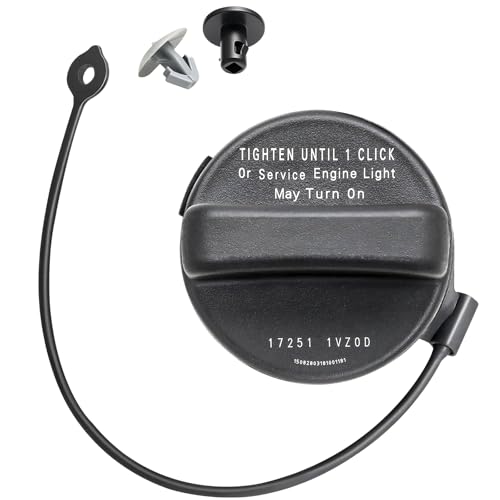
Original factory frame diagrams (Group 51-01) illustrate bare chassis structures as delivered from the assembly line during primary truck manufacturing. The service replacement frame schematic, issued during the Toyota Frame Replacement Campaign, details a comprehensive frame service kit (PNC 51001-XXXXX-XX). This schematic includes supplemental service components not shown on standard assembly line diagrams, such as replacement steering intermediate shaft rag joints, full fuel and brake line bundles, front dynamic suspension crossmembers, boxed-section chassis reinforcements, and complete sub-frame fastener kits containing factory-applied thread-locking compounds.
Can I use a 2003 Tacoma engine wiring diagram for my late-production 2004 model?
While 2003 and 2004 models share the vast majority of their electrical architecture, late-production 2004 models have small changes in their Electronic Control Module (ECM) pinouts, specifically within the automated evaporative emissions check circuit. In late 2004 models, the fuel tank vapor pressure sensor and charcoal canister purge vacuum switching valve (VSV) circuits use different connector housing pinouts at the ECM interface (connectors E5, E6, E7, and E8) compared to 2001-2003 wiring diagrams. Always verify your specific calibration code—located on the metal casing of the ECM behind the passenger glove compartment—prior to performing electrical harness pinning or sensor troubleshooting.
Step-by-Step Guide to Understanding the 2004 Toyota Tacoma Parts Diagram
Identify – Decode the VIN and vehicle production date to select the correct 2WD, PreRunner, or 4WD schematic.
Locate – Isolate the target mechanical system, such as front steering linkage or intake manifold plumbing.
Reference – Match the schematic callout index to the master Toyota parts catalog for updated OEM part numbers.
Connect/Route – Align hardware, brackets, and seals strictly following the diagrammed factory assembly order.
Verify – Torque all fasteners to factory specifications, such as 59 lb-ft for front lower ball joints.
Troubleshoot – Check for binding, fluid leaks, or clearance issues against the layout if the assembly fails to seat properly.