2002 Toyota Tacoma Parts Diagram: 2026 Repair Guide

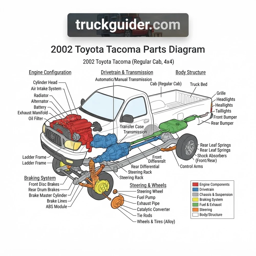
A 2002 Toyota Tacoma parts diagram maps OEM assemblies across sub-systems, including the 2.4L (2RZ-FE), 2.7L (3RZ-FE), or 3.4L (5VZ-FE) powertrains, ladder frame chassis, double-wishbone front suspension, and steering rack layout. It indexes factory part numbers, fastener torque limits, and exploded sub-assemblies for precise maintenance and replacement.
📌 Key Takeaways
- Covers 2RZ-FE (2.4L), 3RZ-FE (2.7L), and 5VZ-FE (3.4L) engine and chassis schematics.
- VIN characters 4 and 5 identify drive configuration (2WD Base, PreRunner, or 4WD).
- Lower ball joint mounting bolts require precisely 37 ft-lbs torque using medium-strength threadlocker.
- Primary structural failure points focus on front lower ball joints and boxed frame rail corrosion.
- Chassis rust remediation requires professional welding; bolt-on suspension and mechanical repairs are DIY-ready.
The 2002 Toyota Tacoma represents the refined late-cycle architecture of Toyota’s first-generation (1995.5–2004) midsize truck platform. Navigating the 2002 Toyota Tacoma parts diagram requires a precise technical understanding of factory Electronic Parts Catalog (EPC) hierarchies, sub-model chassis designations, and engineering production splits. Whether you are overhauling an RZN140 base regular cab or rebuilding a VZN170 PreRunner Xtracab, component identification separates correct OEM installations from costly ordering errors. This technical breakdown deconstructs the factory parts schematics, detailing structural assemblies, powertrain groupings, Part Name Codes (PNC), and model-specific suspension geometry to ensure accurate hardware procurement and factory-grade repairs.
2002 Toyota Tacoma Parts Diagram: Core System Layouts




The OEM Toyota Electronic Parts Catalog organizes the 2002 Tacoma into five primary catalog sections: Tool/Engine/Fuel, Power Train/Chassis, Body, Electrical, and Accessories. To locate any component without ordering mismatches, you must understand how factory schematics segment mechanical sub-assemblies across these core system groupings.
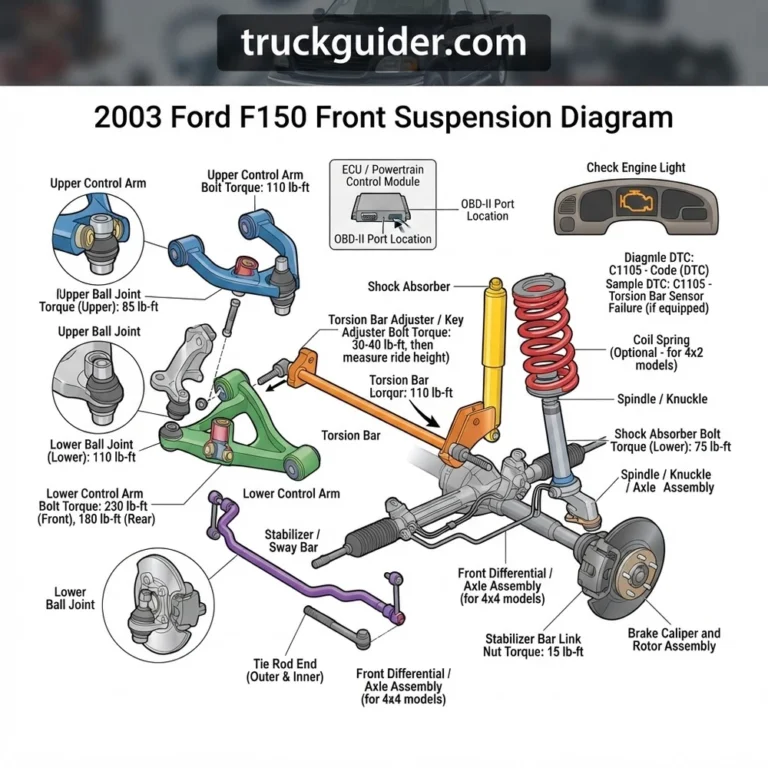
Front Suspension and Steering Linkage Diagram

The front suspension layout represents one of the most significant architectural divisions within the 2002 Tacoma catalog. Factory schematics categorize front-end assemblies into two distinct mechanical configurations:
- 5-Lug Chassis (Base 2WD): Utilizes an independent double-wishbone suspension design featuring upper control arms coupled with coil springs mounted over double-acting hydraulic shocks, controlled via a front stabilizer bar assembly. Steering actuation uses a front-mounted rack-and-pinion assembly (OEM PNC 44250) configured with integrated tie rod assemblies (PNC 45046 outer, PNC 45503 inner) that mount behind the axle centerline.
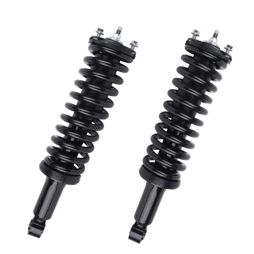
- 6-Lug Chassis (4WD and PreRunner 2WD): Shares an identical structural layout featuring an independent double-wishbone system with a heavy-duty coil-over-strut configuration. The lower control arm (PNC 48068 right-hand, 48069 left-hand) mounts to an inverted lower ball joint assembly (PNC 43330 right-hand, 43340 left-hand) bolted through the steering knuckle base with four high-tensile flange bolts. The power steering rack assembly on 6-lug models incorporates external transfer fluid tubes and larger-diameter tie rod ends to handle increased torsional loads.
Powertrain and Engine Assembly Configuration
The 2002 model year engine schematics are indexed across three distinct engine configurations. Each layout isolates cylinder block components, cylinder head assemblies, air induction systems, and exhaust manifolds:
- 2.4L Inline-4 (2RZ-FE): Found strictly in 5-lug chassis layouts. The schematic highlights a dual overhead cam (DOHC) 16-valve aluminum cylinder head driven by an internal timing chain system with dual internal balance shafts.
- 2.7L Inline-4 (3RZ-FE): Standard on 4WD and PreRunner 4-cylinder trims. While sharing the mechanical architecture of the 2RZ-FE, its exploded view indexes larger cylinder bores, dual balance shafts mounted lower in the crankcase, and a revised oil pan sump configuration designed to clear front differential crossmembers.
- 3.4L V6 (5VZ-FE): The 60-degree V6 layout diagram breaks down a cast-iron block with dual aluminum heads operated by dual overhead camshafts driven via a front-facing reinforced rubber timing belt (PNC 13568). The diagram isolates an air-assisted fuel injection manifold, twin knock sensor sub-assemblies seated beneath the cast aluminum intake plenum, and a coil-on-plug wasted-spark ignition system utilizing three dual-fire ignition coils paired with secondary high-tension ignition leads. For detailed servicing procedures, reference our Tacoma 3.4L 5VZ-FE timing belt replacement procedure.
Drivetrain and Manual/Automatic Transmission Layout
Drivetrain schematics delineate power transmission from the flywheel or torque converter through the drive axles. Manual gearboxes divide into the W59 5-speed manual (paired with the 2RZ-FE and 3RZ-FE engines) and the heavy-duty R150F 5-speed manual (mated to the 5VZ-FE 4WD). Automatic options display the A43D 4-speed automatic on base models and the electronically controlled A340E (2WD/PreRunner) or A340F (4WD) units.
The 4WD drivetrain blueprint details the transfer case assembly (VF1A manual shift or VF2A push-button electric shift). These diagrams catalog internal planetary gearsets, mechanical fork selectors, and front input shaft seals. Crucially, the transfer case diagram isolates the Automatic Disconnecting Differential (ADD) front axle actuator assembly, an electro-pneumatic module responsible for locking the intermediate front axle shaft upon four-wheel-drive engagement.
Rear Suspension and Drive Axle Structure
The rear suspension layout across all 2002 Tacoma platforms utilizes a solid live axle suspended by longitudinal multi-leaf spring packs (PNC 48210 right-hand, 48220 left-hand) controlled by staggered hydraulic shock absorbers. However, differential carriers are segregated into distinct blueprint families:
- 7.5-Inch Differential: Found solely on base 5-lug models, utilizing a two-pinion open differential casing.
- 8.4-Inch (8-Inch 2-Pinion Heavy Duty): Standard on non-locking PreRunner and 4WD configurations, utilizing an oversized bearing cap structure and a continuous outer carrier ring without an inspection cover.
- 8.0-Inch E-Locker Assembly: Specified under the TRD Off-Road package, this diagram indexes a unique axle housing with welded actuator mounting studs, a mechanical shift fork, and an electric locking actuator assembly (PNC 41450-35041) controlled via a dash-mounted switch.
How to Read a 2002 Toyota Tacoma Schematic Step by Step


Procuring correct factory parts for a 2002 Toyota Tacoma requires translating visual catalog schematics into orderable OEM ten- or twelve-digit part numbers. Following this standardized workflow prevents hardware mismatches and returns.
- Extract the Complete 17-Digit VIN and Chassis Code: Locate the vehicle certification label on the driver-side door jamb. Identify the 17-digit VIN and the structural chassis code (e.g.,
VZN170L-CRMDKAB). The prefix confirms the platform: RZN140 denotes 2WD 2.4L Regular Cab 5-lug; VZN170 designates 2WD PreRunner 3.4L Xtracab or Double Cab 6-lug; VZN160 designates 4WD 3.4L Regular Cab. This code dictates your exact catalog filtering parameters. - Navigate the Five Core EPC Systems: Enter the Electronic Parts Catalog and choose the primary functional group. To replace front wheel bearings, navigate to Power Train / Chassis, select Front Axle Hub & Steering Knuckle, and bypass body or transmission groupings.
- Isolate the Callout Number to Reveal the Part Name Code (PNC): Visual schematics use callout numbers to identify components within exploded views. In Toyota technical documentation, these callout numbers correspond to standard five-digit Part Name Codes (PNC). For instance, callout
48068points directly to the right-hand front lower control arm sub-assembly across all chassis variations. The PNC standardizes the general component category across all Toyota vehicle platforms. - Cross-Reference the PNC with the Tabular EPC Ledger: Match the five-digit PNC to the data ledger adjacent to the diagram. The ledger details the full ten-digit base part number (e.g.,
48068-35081) alongside essential technical validation columns: applicable production date ranges, sub-model codes, engine types, and left-hand versus right-hand drive orientations. - Verify Production Date Splits: The 2002 model year spanned from approximately August 2001 to August 2002. Factory revisions occurred midway through this production cycle. Check the date code on your driver-side door placard (e.g.,
11/01for November 2001) against the date ranges listed in the EPC ledger to ensure you do not select a revised component meant for later production runs. - Identify Suffix Codes for Hardware and Gaskets: Standard mechanical components often omit required complementary hardware on the visual schematic. Look for small bracketed sub-callouts attached to the primary PNC; these reveal specialized flange nuts, cotter pins, and crush washers required to complete the assembly according to OEM specifications.
Toyota part numbers follow a structured 10-digit format: XXXXX-YYYYY. The first five digits represent the Part Name Code (PNC), which identifies the exact functional component type (e.g., 04465 denotes front brake pad kits). The final five digits represent the design code, which specifies vehicle model application, material revisions, and engineering updates. A two-digit suffix (e.g., -83) may be appended to designate factory-remanufactured components or specific color codes on interior trim pieces.
2002 Tacoma Drivetrain and Suspension Blueprint Differences


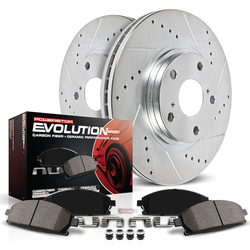

The first-generation Tacoma (1995.5–2004) lineup diverged significantly in its mechanical architecture. A common error when reading a 2002 Toyota Tacoma parts diagram is assuming standard 2WD components interchange with PreRunner sub-models. The PreRunner shares its complete frame, steering architecture, and suspension blueprint with the 4WD platform, differing solely in the absence of a front transfer case, front drive axles, and front differential carrier.
| Mechanical Assembly | Base 2WD (5-Lug Platform) | PreRunner (6-Lug 2WD Platform) | 4WD (6-Lug Platform) |
|---|---|---|---|
| Front Hub & Wheel Bearings | 5×114.3mm bolt circle; integrated tapered roller bearings | 6×139.7mm bolt circle; sealed press-fit cartridge bearing | 6×139.7mm bolt circle; sealed press-fit cartridge with CV splines |
| Front Steering Knuckle | Rearward-facing tie-rod mount, compact cast construction | Forward-facing tie-rod mount, tall forged construction | Forward-facing tie-rod mount with CV shaft pass-through |
| Front Brake Calipers | Single-piston or dual-piston floating caliper | 4-piston fixed caliper (Cast code: S13WB non-ABS, S13WM w/ ABS) | 4-piston fixed caliper (Cast code: S13WB non-ABS, S13WM w/ ABS) |
| Rear Brake Drums | 10.0-inch internal diameter drum assembly | 11.6-inch heavy-duty internal diameter drum assembly | 11.6-inch heavy-duty internal diameter drum assembly |
| Front Suspension Architecture | Double wishbone, standard coil spring over shock absorber | Double wishbone, elevated heavy-duty coil-over-strut | Double wishbone, elevated heavy-duty coil-over-strut |
| Frame Configuration | Standard-height low-clearance fully boxed steel rails | High-clearance reinforced frame identical to 4WD | High-clearance reinforced frame with front diff crossmembers |
Cab variants also dictate driveshaft configuration across the platform. While Regular Cab variants employ a single-piece propeller shaft spanning from the transmission tailhousing to the rear companion flange, Xtracab and Double Cab models use a two-piece driveshaft assembly supported by a frame-mounted Center Support Bearing (PNC 37230). In catalogs, these center bearing brackets are partitioned into 5-lug and 6-lug configurations; interchanging them introduces driveline angle misalignment that causes severe secondary drive vibration under acceleration.
According to factory repair manual specifications for 2002 Tacoma platforms:
• Front Lower Ball Joint Flange Bolts (4 per side, Grade 10.9): 59 N·m (43 ft-lb) — Requires blue medium-strength threadlocker.
• Front Wheel Hub Outer Axle Locknut (4WD/PreRunner): 235 N·m (174 ft-lb).
• Rear Leaf Spring U-Bolt Nuts: 123 N·m (90 ft-lb).
• Front Steering Tie Rod End Outer Castle Nut: 91 N·m (67 ft-lb) with cotter pin reinstalled.
Troubleshooting 2002 Toyota Tacoma Parts Diagram Ordering Errors


Ordering parts for a first-generation Tacoma using visual schematics frequently leads to catalog errors due to shared names across completely different sub-models. Review these common schematic ordering issues before completing component requisitions.
Conflating PreRunner (6-Lug 2WD) with Base 5-Lug Components
The single most frequent mistake involves selecting parts from the “2WD” catalog category without verifying lug count. The PreRunner is functionally a two-wheel-drive truck built on a complete four-wheel-drive structural frame. Selecting base 2WD components results in receiving undersized 5-lug brake rotors, incorrect outer tie rod ends with non-compatible taper angles, and coil springs with inadequate load ratings. When working on a PreRunner, navigate exclusively to 6-lug or 4WD mechanical sub-groups for suspension, steering, and braking components.
Brake System Diagram Callout Mismatches
In the 2002 Tacoma brake system schematic, two distinct front brake caliper options exist under the same base PNC 47730 (right-hand) and 47750 (left-hand). Mechanics often order the wrong unit because catalogs do not clearly identify casting variations without verifying option codes:
- Casting S13WB: Accommodates a standard, non-vented rotor configuration found primarily on non-ABS equipped commercial models.
- Casting S13WM: Designed with a wider throat to clear the 22mm-thick vented brake rotor installed on ABS-equipped 4WD and PreRunner packages. For complete caliper rebuilding steps, refer to our first-generation Tacoma front brake overhaul guide.
Confirm the four-digit casting alphanumeric stamped directly into the outer iron body of your original caliper before finalizing an order from the parts ledger.
Relying Solely on Part Name Codes (PNC)
A Part Name Code (PNC) is an index classification, not a part number. For example, callout 17801 designates the engine air filter across all Toyota platforms worldwide. However, on a 2002 Tacoma, selecting PNC 17801 without cross-referencing your engine code can yield part number 17801-07010 (round filter for 2RZ/3RZ 4-cylinder engines) or 17801-07020 (flat rectangular panel filter for the 5VZ-FE 3.4L V6). Always resolve the five-digit PNC to the complete ten-digit OEM part number via your specific vehicle model configuration.
The front lower ball joint on 2002 6-lug Tacomas operates in an inverted-tension configuration, pulling directly away from the steering knuckle under load. Never reuse the four M10x1.25 flange mounting bolts (OEM Part Number 90119-10928). These are torque-to-yield fasteners subject to fatigue. Always install new OEM grade 10.9 factory bolts coated with medium-strength thread locking compound, torqued to exactly 43 ft-lb (59 N·m). Failure to follow this assembly procedure can cause structural ball joint detachment while driving.
Critical Assemblies in the 2002 Toyota Tacoma Parts Breakdown
Certain high-liability structural assemblies require strict adherence to exploded schematics to maintain vehicle safety and proper hardware orientation.
Front Lower Ball Joint (LBJ) Assembly Sequence
The front suspension schematic illustrates the inverted lower ball joint design unique to 1995.5–2004 Tacomas. Unlike modern designs where the vehicle’s weight presses the ball stud securely into its seat, the 2002 6-lug suspension places the ball joint in tension, pulling the ball stud outward from the housing. The schematic identifies the critical relationship between the knuckle base, the dust seal guard (PNC 43346), the lower ball joint casting (PNC 43330/43340), and the outer tie-rod end attachment point.
The diagram specifies four precision-machined flange bolts per side. These bolts must pass upward through the ball joint casting and thread cleanly into the steering knuckle base. Installing non-OEM hardware or improper bolt lengths compromises thread engagement depth, leading to shearing under sudden off-camber suspension loads.
Chassis, Frame Crossmembers, and Structural Rust Points
The 2002 Tacoma frame layout indexes a fully boxed front boxed section transitioning into a C-channel configuration directly behind the front cab mounts. This chassis represents the central focus of the widespread Toyota frame rust safety campaign (NHTSA Campaign 08V194000). The diagram details structural crossmember assemblies that require close inspection:
- Crossmember No. 2 (Engine/Front Suspension Support): Forms the structural foundation for lower control arm cam adjustment bolts.
- Crossmember No. 3 (Transmission and Transfer Case Support): Accommodates the transmission rubber insulator mount.
- Crossmember No. 4 & Rear Leaf Spring Hangers: High-stress weld zones susceptible to internal moisture entrapment and frame perforation. Before ordering replacement spring shackles, reference our Tacoma frame rust inspection and reinforcement checklist to confirm structural integrity.
Steering Rack Guide and Bushing Assembly
The rack-and-pinion schematic isolates internal maintenance assemblies designed to correct loose or wandering steering. Callout 44236 indexes the updated roller-style steering rack guide sub-assembly (OEM Part Number 44236-35010). This assembly replaced the earlier brass friction-shoe design to resolve chronic steering wheel shimmy over washboard surfaces. The diagram also illustrates the three-point rubber mounting bushing set (PNC 44251B and 44251C), showing how the vertical D-bushing and horizontal through-bolt bushings decouple road vibration from the passenger compartment.
Frequently Asked 2002 Toyota Tacoma Parts Diagram Questions
How do I distinguish between a 5-lug and 6-lug suspension diagram in the Toyota EPC?
Look at the vehicle model designation on the diagram header. 5-lug models are designated with an RZN140 or RZN150 chassis code. 6-lug models (both PreRunner and 4WD) are categorized under RZN161, RZN171, VZN160, or VZN170. Additionally, 5-lug diagrams illustrate an integrated wheel spindle hub, whereas 6-lug diagrams clearly show a four-bolt lower ball joint mounting flange and elevated strut assemblies.
What does the 5-digit number on a Toyota parts diagram mean?
The 5-digit number is a Part Name Code (PNC). It serves as a generic component identifier across the Toyota catalog system. For instance, PNC 04465 always denotes front brake pads, and PNC 90915 indicates an oil filter. A PNC is not a complete orderable part number; you must cross-reference it within the catalog ledger to locate the full 10-digit OEM part number tailored to your truck’s specific VIN, engine, and production date.
Why does my 2002 Tacoma parts diagram show two different oil filter part numbers?
The schematic accounts for different engine configurations available in 2002. Four-cylinder engines (2.4L 2RZ-FE and 2.7L 3RZ-FE) use OEM filter part number 90915-YZZD1 (or equivalent small-case filtration), whereas the 3.4L V6 5VZ-FE specifies OEM part number 90915-YZZD3, which provides a larger internal filter media surface and an internal bypass valve calibrated for higher oil delivery rates.
How do I identify the correct rear axle differential assembly in the parts schematic?
Check the axle code on the driver’s door jamb certification placard (e.g., A01A or B03B) and look for dash switch options. Tacomas equipped with the factory locking rear differential (TRD Off-Road package) show an electric actuator mounted to the differential carrier and use part number family 41110-35780. Non-locking 6-lug models use the standard 8.4-inch carrier assembly (part number family 41110-35750), which lacks the actuator mounting port on the carrier face.
Where can I find paint and interior trim codes to match diagram parts?
Locate the metal vehicle identification plate fixed to the driver-side door jamb. At the bottom of this label, you will find a line marked C/TR (Color/Trim). The first three alphanumeric characters represent the exterior body paint code (e.g., 1D4 for Titanium Metallic), and the subsequent four characters indicate the interior trim configuration and fabric code (e.g., FC16 for Oak or FA17 for Moon Mist Charcoal). Use these suffix indicators when selecting color-matched interior dash components, door cards, and seat upholstery from the EPC.
Step-by-Step Guide to Understanding the 2002 Toyota Tacoma Parts Diagram
Identify – Determine your vehicle trim, engine code (2RZ/3RZ/5VZ), and 5-lug or 6-lug chassis configuration.
Locate – Isolate the target subsystem schematic, such as front suspension or intake manifold assembly.
Reference – Match the component callout number to the OEM parts list to confirm the exact part number.
Connect/Route – Align replacement hardware and structural brackets following the exploded visual layout and orientation arrows.
Verify – Fasten all bolts to factory torque specifications and ensure dynamic clearances match diagram tolerances.
Troubleshoot – Inspect mating surfaces, seal seating, and harness clips if misalignment, leaks, or binding occurs.