2003 Toyota Tacoma 3.4 Belt Diagram: Proper Routing 2026

The 2003 Toyota Tacoma 3.4L 5VZ-FE engine uses three independent drive belts driven by the crankshaft pulley: power steering (outer), air conditioning (middle), and alternator/water pump/fan (inner). Tension is adjusted manually via dedicated tensioner bracket bolts on the alternator, power steering pump pivot, and the AC idler pulley assembly.
📌 Key Takeaways
- Features a 3-belt multi-rib system with no single automatic belt tensioner.
- Belt rib sizes: Alternator is 4PK1050, A/C is 4PK870, and Power Steering is 4PK1070.
- Deflection spec: 1/4-inch (6-8mm) under 22 lbs thumb pressure on new belts; lock bolts torque to 29-32 ft-lbs.
- Most common failure: Over-tightening tensioner bolts before loosening the idler or pivot lock nut, which strips threads.
- DIY accessible in 1-2 hours using 12mm and 14mm ratcheting wrenches; seek a pro if crank seal oil contamination is present.
Maintaining the multi-belt accessory drive on the Toyota 5VZ-FE 3.4-liter V6 requires precise routing, proper tensioning, and accurate pulley alignment. The 2003 toyota tacoma 3.4 belt diagram illustrates a classic three-belt independent accessory system driven by the crankshaft harmonic balancer. Unlike modern modular serpentine layouts with spring-loaded automatic tensioners, this platform relies entirely on manual mechanical adjusters across dedicated drive tracks. Installing, aligning, or diagnosing these belts demands an understanding of the relationship between the crank pulley, fan bracket, alternator, air conditioning compressor, and power steering pump to ensure optimal accessory output and eliminate premature drive component failure.
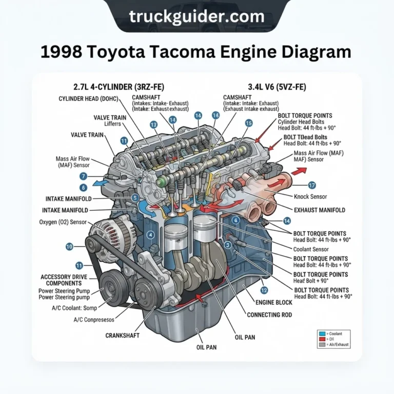
2003 Toyota Tacoma 3.4L 5VZ-FE Accessory Drive Belt Diagram: Depicting Crankshaft Harmonic Balancer (3-Track), Alternator & Fan Bracket Loop, A/C Compressor Loop with Manual Idler Tensioner Pulley, and Power Steering Pump Loop.
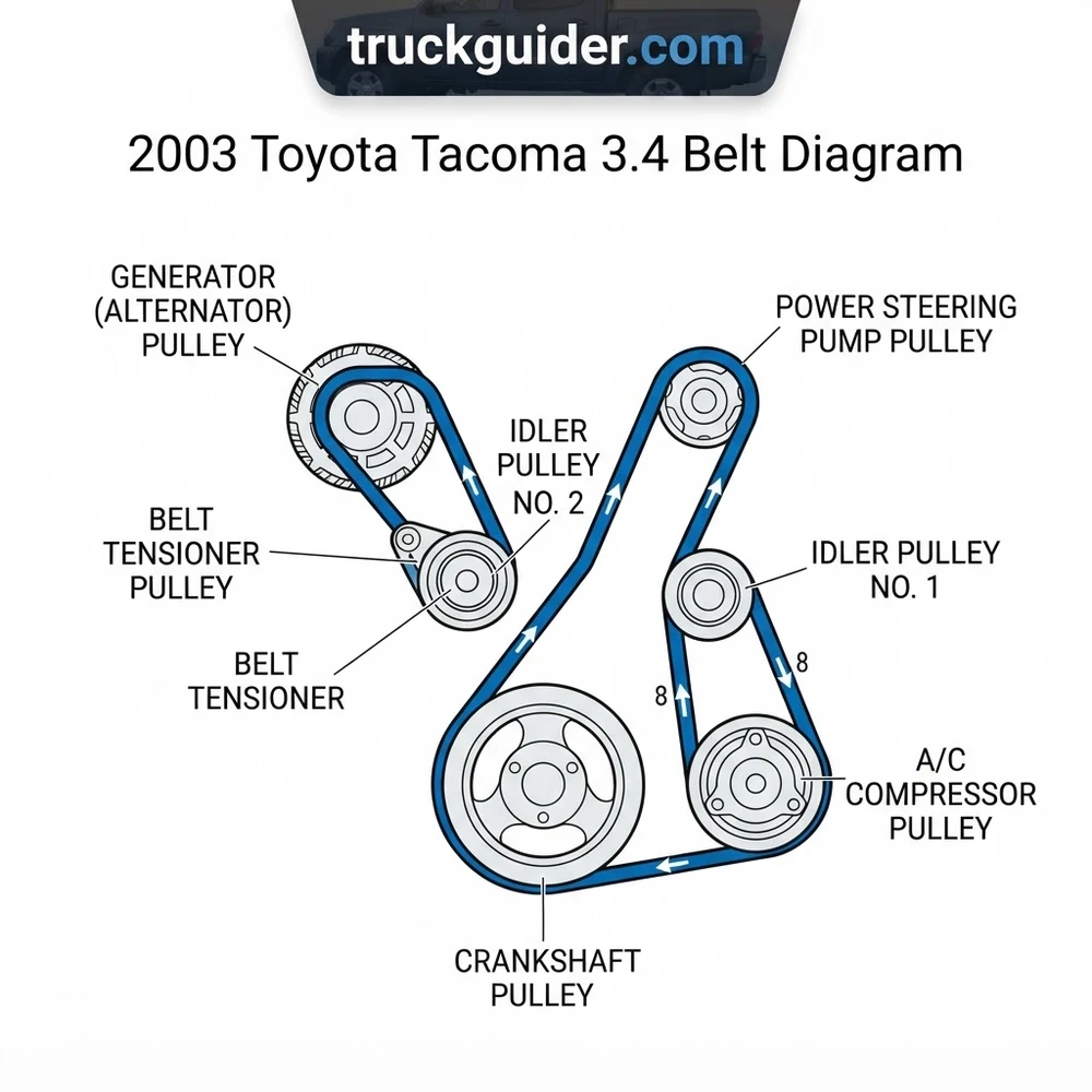
2003 Toyota Tacoma 3.4 Belt Diagram and Pulley Layout Breakdown


The 2003 Toyota Tacoma equipped with the 3.4L V6 (5VZ-FE engine) utilizes a three-belt multi-ribbed accessory configuration. Every external accessory takes its rotational torque directly from the crankshaft harmonic balancer, which features three independent V-ribbed track sections machined onto its outer circumference. To read and execute repairs using the 2003 toyota tacoma 3.4 belt diagram, technicians must understand the individual pulley stations and their relationship to engine accessories.
The engine’s cooling fan does not mount directly to the water pump. On the 5VZ-FE, the water pump is driven internally by the rubber toothed timing belt behind the front timing covers. The radiator cooling fan spins on an independent, bearing-supported fan bracket pulley driven externally by the alternator belt track. For further engine timing service, review the related Toyota 5VZ-FE Timing Belt and Water Pump Guide.
Crankshaft Harmonic Balancer and 5VZ-FE Multi-Groove Drive

At the center of the belt drive is the crankshaft harmonic balancer. This component dampens torsional vibrations from the crankshaft while turning three independent belts. The pulley contains three specific drive zones, arranged front-to-back:
- Track 1 (Outermost / Front Track): Drives the alternator and the fan bracket pulley.
- Track 2 (Center Track): Drives the air conditioning (A/C) compressor and interfaces with an adjustable mechanical idler pulley.
- Track 3 (Innermost / Rear Track): Drives the power steering vane pump pulley closest to the cylinder block.
Understanding this front-to-rear order is essential when reviewing the pulley diagram. You cannot remove or install an inner belt without first clearing the outer belts standing in front of it on the harmonic balancer.
Fan Bracket Pulley and Accessory Drive Architecture
The fan bracket pulley assembly mounts directly to the front engine casting above the water pump housing. It incorporates a heavy-duty dual-row bearing assembly and holds the mechanical viscous fan clutch and radiator blade assembly. When reading the 2003 toyota tacoma 3.4 belt diagram, notice that this pulley acts as an upper intermediary idler for the outer belt loop. Because it is non-adjustable, tension for this front drive circuit is modulated entirely by shifting the alternator housing along its dedicated curved adjustment bracket.
The power steering pump sits on the upper driver side of the engine block, driven by the innermost rear crankshaft track. Tension adjustment for this accessory is carried out by loosening pivot hardware through the access holes in the power steering pulley face and turning a secondary tension bolt beneath the reservoir bracket. The middle track engages the lower passenger-side A/C compressor and loops upward over a dedicated idler pulley assembly that provides the mechanical belt tensioner adjustment for the circuit.
OEM Belt Part Numbers, Rib Counts, and Belt Sizes for the 3.4L V6



The 5VZ-FE platform specifies multi-ribbed V-belts (commonly designated as V-ribbed belts under metric PK classifications). Each belt is classified by its rib count and effective length in millimeters. Using the correct belt part number ensures proper seated depth within the pulley grooves and provides adequate adjustment travel along the manual tensioner brackets.
Unlike industrial power equipment featuring spring-assisted mechanical deck engagement systems, the automotive accessory drive relies entirely on fixed center-to-center friction fitment. If a belt size is too long, the adjustment bolt will bottom out before achieving nominal deflection. If the belt is undersized, you risk severe side-load stress on the internal bearings of the alternator, fan bracket, or power steering pump.
| Accessory Circuit | OEM Toyota Part # | Bando / Dayco Standard | Belt Size / Metric Spec |
|---|---|---|---|
| Alternator & Fan Belt (Track 1) | 90080-91090-83 (or 99364-81050) | 4PK1050 / 5040413 | 4 Ribs x 1050 mm (41.3 in.) |
| A/C Compressor Belt (Track 2) | 90080-91126-83 (or 99364-20870) | 4PK870 / 5040343 | 4 Ribs x 870 mm (34.3 in.) |
| Power Steering Belt (Track 3) | 90080-91122-83 (or 44368-04010) | 4PK1070 / 5040421 | 4 Ribs x 1070 mm (42.1 in.) |
Toyota 5VZ-FE Accessory V-Ribbed Belt Specifications
When purchasing an OEM belt or top-tier aftermarket replacement (such as Bando or Mitsuboshi, the original equipment suppliers to Toyota), verify that all three belts feature the 4PK cross-section profile. The 4PK designation signifies a 4-rib configuration with a 3.56 mm rib pitch. Using a 3-rib or 5-rib belt on these pulleys will result in immediate rib shear or belt derailment.
Take note of manufacturing variations on early vs. late 5VZ-FE engines. While 2003 model year Tacomas uniformly utilize the 4PK1050 alternator belt, earlier model years (1995.5–1998) occasionally required a 4PK1045 or 4PK1055 depending on alternator amperage outputs (60A vs 70A vs 80A Denso units). Always confirm that your replacement alternator matches factory case dimensions if an aftermarket unit was previously fitted.
2003 Toyota Tacoma 3.4 Belt Routing Path and Step-by-Step Installation


Because the accessory belts are layered sequentially on the crankshaft pulley, service procedures must follow a strict reverse-removal and forward-installation order. Installing these belts in the wrong sequence will require total disassembly of previously tightened hardware. Reference the numbered path below to ensure proper belt placement along the correct belt routing path.
Disconnect the negative terminal of the battery before servicing accessory belts. Accidental contact between your wrench and the positive terminal of the 80A alternator while manipulating the adjustment bracket will cause a direct short circuit, blown fusible links, or harness fires.
-
Relieve Tension and Remove the Alternator & Fan Belt (Outer Track 1):
Loosen the 14 mm alternator lower pivot bolt underneath the front casing. Next, loosen the 12 mm lock bolt securing the alternator to the curved adjustment slider bracket. Turn the 12 mm horizontal tension adjustment screw counterclockwise to relieve tension on the alternator. Push the alternator toward the engine block, slip the belt off the upper fan bracket pulley and alternator pulley, and pull it past the cooling fan blades. -
Relieve Tension and Remove the A/C Compressor Belt (Middle Track 2):
Locate the A/C belt idler tensioner pulley assembly mounted on the lower passenger side of the engine timing cover. Loosen the 14 mm center locking nut on the face of the idler pulley by 1 to 2 turns. Do not remove this nut completely. Rotate the vertical 12 mm adjustment bolt (accessible from underneath the vehicle through the skid plate opening) counterclockwise to lower the idler pulley assembly. Once slack, disengage the belt from the middle groove of the harmonic balancer and the A/C compressor pulley. -
Relieve Tension and Remove the Power Steering Pump Belt (Inner Track 3):
Access the power steering pump on the upper driver side. Rotate the power steering pulley by hand until the cutouts in the pulley face align with the 14 mm pivot bolt behind it; loosen this bolt. Loosen the 14 mm lock bolt located on the adjustment slide bracket behind the pump. Use a pry tool or turn the manual 12 mm adjustment jack-bolt counterclockwise to pivot the power steering pump toward the engine block. Slide the belt off the pump pulley and inner crankshaft track, clearing the cooling fan blades. -
Install the New Power Steering Belt (Inner Track 3):
Route the 4PK1070 belt past the cooling fan blades. Seat the belt grooves squarely into the innermost track (closest to the block) of the crankshaft harmonic balancer. Route the upper loop over the power steering pump pulley. Ensure all 4 ribs sit flush in both pulley grooves before applying initial tension. -
Install the New A/C Compressor Belt (Middle Track 2):
Guide the 4PK870 belt around the middle track of the crankshaft harmonic balancer and loop it around the lower A/C compressor clutch pulley. Bring the top portion of the belt run beneath the smooth/grooved contact surface of the A/C belt idler tensioner pulley. Verify that the belt is not caught on adjacent timing cover lip tabs. -
Install the New Alternator & Fan Belt (Outer Track 1):
Maneuver the 4PK1050 belt past the fan blades. Wrap the bottom loop around the outermost track of the harmonic balancer. Wrap the upper loop around the fan bracket pulley, and feed the remaining section over the alternator drive pulley. Confirm full groove engagement on all three stations.
For related maintenance protocols concerning power delivery components, review our procedural overview on Toyota Tacoma Drivetrain and Accessory Maintenance to cross-reference accessory load requirements with charging system load profiles.
2003 Tacoma 3.4 Belt Tensioner Adjustment and Deflection Specs


Because the 2003 3.4L Tacoma does not utilize spring-loaded tensioner pulleys for its auxiliary belts, belt tension must be manually adjusted and measured. Excessive belt tension accelerates bearing failure in the alternator, water pump housing, and fan bracket. Under-tensioning causes instantaneous belt slip, squeal, glazing, and battery discharge under load.
Deflection measurements are checked by applying 98 N (10 kgf / 22 lbf) of perpendicular force at the midpoint between the two furthest pulleys on that belt circuit. Always rotate the engine clockwise two full rotations by the crank bolt to seat the belts into the grooves before taking final measurements.
A/C Belt Idler Tensioner Pulley Calibrations
The A/C circuit relies on a vertical screw-jack mechanism acting upon the idler pulley bracket. Turning the vertical 12 mm adjustment bolt clockwise raises the pulley, increasing track tension. Once proper tension is achieved, the 14 mm center idler pulley nut must be torqued down. Failure to lock the center nut will allow the adjustment bolt to back out or snap due to operational vibration.
- New Belt Deflection: 5.0 to 6.0 mm (0.20 to 0.24 in.) at 98 N (22 lbf).
- Used Belt Deflection: 6.5 to 8.0 mm (0.26 to 0.31 in.) at 98 N (22 lbf).
- Idler Pulley Center Lock Nut Torque: 29 ft-lbs (39 Nm).
- Vertical Tensioner Adjusting Bolt: Set to achieve specified deflection (do not over-torque beyond mechanical travel).
Alternator and Power Steering Mechanical Tension Points
The alternator and power steering systems require coordinated adjustment between pivot hardware, adjustment slot slider bolts, and draw bolts. When tensioning the alternator belt, turn the horizontal adjustment bolt clockwise until belt deflection on the span between the fan bracket pulley and the alternator reaches the target metric value.
- Alternator Belt Deflection (New): 5.0 to 6.5 mm (0.20 to 0.26 in.) at 98 N.
- Alternator Belt Deflection (Used): 7.0 to 9.0 mm (0.28 to 0.35 in.) at 98 N.
- Alternator Lower Pivot Bolt Torque: 38 ft-lbs (51 Nm).
- Alternator Adjustment Lock Bolt Torque: 13 ft-lbs (18 Nm).
- Power Steering Belt Deflection (New): 6.0 to 7.5 mm (0.24 to 0.30 in.) at 98 N.
- Power Steering Belt Deflection (Used): 8.0 to 10.0 mm (0.31 to 0.39 in.) at 98 N.
- Power Steering Pump Pivot and Lock Bolts Torque: 32 ft-lbs (43 Nm).
If you use a mechanical belt tension gauge (such as a Burroughs or Nippondenso gauge), a brand-new belt should measure between 120 and 150 lbs of tension, settling to approximately 70 to 90 lbs after its initial break-in period.
Diagnosing 2003 Toyota Tacoma 3.4 Belt Squeal and Pulley Separation
High-pitched squealing from the front of the 5VZ-FE engine bay is often misdiagnosed as an improper belt tension issue or glazed rubber compound. On the 2003 Tacoma 3.4L, several mechanical failure points require systematic troubleshooting to avoid unnecessary belt replacements.
- Harmonic Balancer Rubber Bonding Failure: The most critical failure on aging 5VZ-FE engines is harmonic balancer delamination. The crankshaft pulley is constructed as a two-piece assembly joined by a pressed-in rubber dampening ring. Over time, heat, engine oil leaks, and age cause this rubber to shear. The outer pulley ring holding the accessory tracks begins to slip independently of the inner hub keyed to the crankshaft. This condition causes persistent belt chirp, intermittent power steering loss, and dead battery issues, even when belts are brand new and adjusted to exact specifications.
- Harmonic Balancer Alignment Test: Draw a straight radial line across the front face of the harmonic balancer using a paint marker, from the inner hub bolt washer across the rubber dampener to the outer belt ring. Run the engine under high electrical and A/C load. Turn the engine off and inspect the mark. If the painted segments of the line no longer align, the harmonic balancer has separated internally and must be replaced immediately to prevent catastrophic failure or timing cover destruction.
- A/C Belt Idler Tensioner Pulley Bearing Failure: The sealed ball bearing inside the A/C idler pulley sits low in the engine bay and is susceptible to road salt, dust, and water ingress. Remove the A/C belt and spin the idler by hand. Any roughness, axial play, or rattling indicates worn ball bearings. A failing idler bearing generates high-frequency whining that closely mimics alternator failure.
- Fan Clutch Bracket Pulley Play: The fan bracket pulley carries high radial loads from the alternator belt and the mass of the spinning mechanical fan. Check the assembly for vertical or horizontal play by grasping the fan blades and rocking them gently front-to-back. Any noticeable movement indicates internal bracket bearing wear. Left unaddressed, a seized bracket bearing will snap the outer accessory belt and compromise radiator integrity. For complementary chassis-level service details, view our technical guide on Toyota Tacoma Front End Service and Component Diagnostics.
2003 Toyota Tacoma 3.4 Belt Diagram and Maintenance FAQs
Does the 2003 Toyota Tacoma 3.4L V6 use an automatic belt tensioner?
No. The 5VZ-FE 3.4L engine accessory drive system uses entirely manual mechanical adjustment points. Unlike later 4.0L V6 (1GR-FE) engines, which use a spring-loaded self-tensioner on a single serpentine belt, the 2003 3.4L Tacoma requires manual adjustment of every belt via slide brackets, pivot bolts, and jack-screws.
What is the correct tension deflection for a new 5VZ-FE drive belt?
For a newly installed belt, deflection should measure between 5.0 and 6.0 mm (0.20 to 0.24 inches) on the alternator and A/C belts, and 6.0 to 7.5 mm (0.24 to 0.30 inches) on the power steering belt when applying 98 N (22 lbf) of force midway between pulleys. After running the engine for at least 5 minutes, recheck tension to compensate for initial belt stretch.
Can a failing fan clutch bracket mimic a bad idler pulley?
Yes. The fan bracket assembly uses an integrated internal bearing pressed into the aluminum housing. When this bearing begins to fail, it creates grinding noises and harmonic vibrations that closely mimic a worn A/C idler tensioner pulley or alternator bearing. Because the fan bracket pulley has no internal clutch mechanism, it must be replaced as an entire sub-assembly if bearing looseness is detected.
How do you diagnose harmonic balancer separation on the 3.4L Tacoma?
Perform the “paint stripe test.” Use a white grease pencil or paint marker to draw a continuous straight line from the center crank bolt out to the exterior accessory belt track across the face of the harmonic balancer. Operate the vehicle with high accessory load (A/C on high, high beams active, turning steering wheel). If the line breaks into offset segments, the outer ring has separated from the rubber damper core, necessitating crank pulley replacement.
What happens if the accessory drive belts are over-tightened?
Over-tightening drive belts on the 5VZ-FE places severe side-loading forces on external bearings. This typically causes premature bearing failure in the alternator, front power steering pump shaft seal leaks, fan bracket pulley bearing damage, and premature wear on the crankshaft thrust washers. Follow the recommended factory deflection specs to ensure optimal accessory output without overloading drive bearings.